Mitsubishi Electric MELSERVO-J4 MR-J4-TM Instruction Manual
General-purpose ac servo/multi-network interface ac servo/servo amplifier
Hide thumbs
Also See for MELSERVO-J4 MR-J4-TM:
- Transition handbook (708 pages) ,
- Instruction manual (646 pages) ,
- Instruction manual trouble shooting (94 pages)

Related Manuals for Mitsubishi Electric MELSERVO-J4 MR-J4-TM


Summary of Contents for Mitsubishi Electric MELSERVO-J4 MR-J4-TM
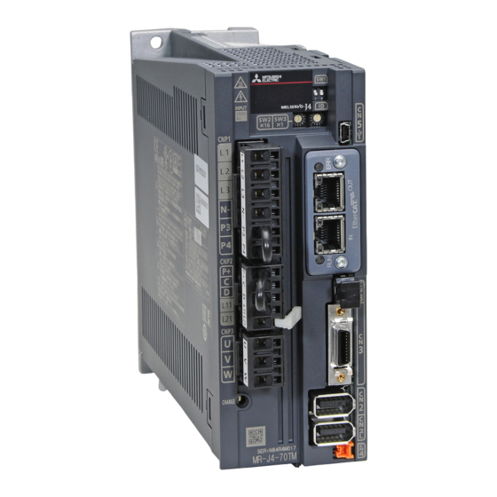
- Page 1 General-Purpose AC Servo Multi-network Interface AC Servo MODEL MR-J4-_TM_ SERVO AMPLIFIER INSTRUCTION MANUAL (PROFINET)
-
Page 2: Safety Instructions
Safety Instructions Please read the instructions carefully before using the equipment. To use the equipment correctly, do not attempt to install, operate, maintain, or inspect the equipment until you have read through this Instruction Manual, Installation guide, and appended documents carefully. Do not use the equipment until you have a full knowledge of the equipment, safety information and instructions. - Page 3 1. To prevent electric shock, note the following WARNING Before wiring and inspections, turn off the power and wait for 15 minutes or more until the charge lamp turns off. Then, confirm that the voltage between P+ and N- is safe with a voltage tester and others. Otherwise, an electric shock may occur.
- Page 4 CAUTION Ensure that polarity (+/-) is correct. Otherwise, a burst, damage, etc. may occur. The servo amplifier heat sink, regenerative resistor, servo motor, etc., may be hot while the power is on and for some time after power-off. Take safety measures such as providing covers to avoid accidentally touching them by hands and parts such as cables.
- Page 5 (2) Wiring CAUTION Wire the equipment correctly and securely. Otherwise, the servo motor may operate unexpectedly. Do not install a power capacitor, surge killer, or radio noise filter (FR-BIF(-H) option) on the servo amplifier output side. To avoid a malfunction, connect the wires to the correct phase terminals (U, V, and W) of the servo amplifier and servo motor.
- Page 6 (4) Usage CAUTION Provide an external emergency stop circuit to ensure that operation can be stopped and power switched off immediately. Do not disassemble, repair, or modify the equipment. Before resetting an alarm, make sure that the run signal of the servo amplifier is off in order to prevent a sudden restart.
- Page 7 (6) Maintenance, inspection and parts replacement CAUTION Make sure that the emergency stop circuit operates properly such that an operation can be stopped immediately and a power is shut off by the emergency stop switch. It is recommended that the servo amplifier be replaced every 10 years when it is used in general environment.
- Page 8 «About the manuals» You must have this Instruction Manual and the following manuals to use this servo. Ensure to prepare them to use the servo safely. Relevant manuals Manual name Manual No. MELSERVO MR-J4-_TM_ Servo Amplifier Instruction Manual SH(NA)030193 MELSERVO-J4 Servo Amplifier Instruction Manual (Troubleshooting) SH(NA)030109 MELSERVO MR-D30 Instruction Manual (Note 5) SH(NA)030132...
- Page 9 MEMO A - 8...
-
Page 10: Table Of Contents
CONTENTS 1. PROFINET COMMUNICATION 1- 1 to 1- 6 1.1 Description ............................1- 1 1.2 Communication specifications ......................1- 3 1.3 Startup .............................. 1- 4 1.4 Network disconnection procedure ....................1- 5 1.5 Object dictionary (OD) ........................1- 5 1.5.1 Section definition of object dictionary ..................1- 5 2. - Page 11 6.3 Profile position mode (pp) ......................... 6- 2 6.4 Profile velocity mode (pv) ......................... 6- 7 6.5 Profile torque mode (tq) ........................6-13 6.6 Homing mode (hm) .......................... 6-16 7. WEB SERVER 7- 1 to 7- 2 8. MANUFACTURER FUNCTIONS 8- 1 to 8-20 8.1 PROFIdrive parameters for status monitor ..................
-
Page 12: Profinet Communication
1. PROFINET COMMUNICATION 1. PROFINET COMMUNICATION 1.1 Description PROFINET represents the communication standard for the automation which was made by PI (PROFIBUS & PROFINET International). The PROFINET IO communication is available when the PROFINET network module (ABCC-M40-PIR manufactured by HMS Industrial Networks) is connected to the MR-J4-_TM_ servo amplifier. The MR-J4- _TM_ servo amplifier to which the PROFINET network module is connected is an IO device. - Page 13 1. PROFINET COMMUNICATION The following table shows explanation of terms applied to PROFINET standard used in this manual. Term Explanation PROFINET (PROFINET IO) PROFINET has two application types: PROFINET IO and PROFINET CBA. This product is compatible with PROFINET IO. PROFINET IO is based on a communication between controllers and other devices.
-
Page 14: Communication Specifications
1. PROFINET COMMUNICATION 1.2 Communication specifications The following shows the communication specifications. Item Description Remark PROFINET communication PROFINET IO specifications Real Time (RT) communication PROFIdrive v4.1 Physical layer 100BASE-TX Communication connector RJ45, 2 ports (port 1, port 2) Communication cable CAT5e, shielded twisted pair (4 pair) straight cable Double-shielded type recommended Network topology Line, Star, Ring, or a connection topology where... -
Page 15: Startup
The following lists the tools used for starting up. Tool Explanation Manufacturer MR Configurator 2 (Ver. This software is used to configure You can purchase this software from Mitsubishi Electric 1.55H or later) various settings of the servo amplifier Corporation. and helps maintenance works. AnybusIPconfig... -
Page 16: Network Disconnection Procedure
1. PROFINET COMMUNICATION 1.4 Network disconnection procedure To disconnect the network by stopping device operation or other means, follow the procedure shown below. (1) When the servo motor is during operation, stop the servo motor depending on the operation mode. (2) When the servo amplifier is in servo-on status, set the off command for Controlword to establish the servo-off status. - Page 17 1. PROFINET COMMUNICATION MEMO 1 - 6...
-
Page 18: Profinet Network Module (Abcc-M40-Pir)
2. PROFINET NETWORK MODULE (ABCC-M40-PIR) 2. PROFINET NETWORK MODULE (ABCC-M40-PIR) The PROFINET communication with an MR-J4-_TM_ servo amplifier requires the PROFINET network module (ABCC-M40-PIR). The following shows the details. 2.1 Specifications Category Description Product name ABCC-M40-PIR Model AB6938-C Manufacturer HMS Industrial Networks External interface MR-J4-_TM_ servo amplifier connecting interface: Compact flash connector with standard 50 pins PROFINET communication port interface: RJ45 connector... -
Page 19: Led Display
2. PROFINET NETWORK MODULE (ABCC-M40-PIR) 2.3 LED display The PROFINET Network module (ABCC-M40-PIR) has each LED of the Network Status, Module Status, and Link/Activity. The following shows the LED indication definitions. LED status Definition An LED remains lit. Extinguished An LED remains extinguished. Flickering An LED is switching between lit and extinguished at 10 Hz cycles (every 50 ms). -
Page 20: Ethernet Cable Connection
2. PROFINET NETWORK MODULE (ABCC-M40-PIR) 2.4 Ethernet cable connection POINT Use a twisted pair cable (double shielded) compliant with Ethernet Category 5e (100BASE-TX) or higher as an Ethernet cable. The maximum cable length between nodes is 100 m. When the RJ45 PROFINET communication ports (port 1 and port 2) are not used, leave these ports open. The first axis The second axis The final axis... - Page 21 2. PROFINET NETWORK MODULE (ABCC-M40-PIR) MEMO 2 - 4...
-
Page 22: Process Data (Cyclic Data Exchange)
3. PROCESS DATA (CYCLIC DATA EXCHANGE) 3. PROCESS DATA (CYCLIC DATA EXCHANGE) The communication can send and receive command data/feedback data between a master (controller) and slaves (servo amplifier) at a constant cycle. The following communication format is supported. Telegram Name Description Standard Telegram 1... - Page 23 3. PROCESS DATA (CYCLIC DATA EXCHANGE) (3) Telegram 102 IO Data Data length Direction Name Remark number (Bit) Controller to Drive Modes of operation Refer to chapter 5/ chapter 6. Reserved Map size: 48 bytes Controlword (Note) Control DI 1 Control DI 2 Control DI 3 Target torque...
-
Page 24: Acyclic Data Exchange
4. ACYCLIC DATA EXCHANGE 4. ACYCLIC DATA EXCHANGE 4.1 Acyclic data exchange communication format PROFIdrive parameters are transmitted/received between the master controller and slave with acyclic communication. The transmission/receive will be in accordance with the following formats. The maximum size is 240 bytes. Refer to the standards of PROFIdrive for details. -
Page 25: Error Number
4. ACYCLIC DATA EXCHANGE 4.2 Error number The following error number will be returned depending on conditions during Acyclic communication. Error No. Name Description Impermissible parameter number Access to non-existent PROFIdrive parameter Parameter value cannot be changed Writing to unwritable PROFIdrive parameter Low or high limit exceeded Out of setting range Faulty subindex... - Page 26 4. ACYCLIC DATA EXCHANGE 4.3.2 Operating mode (P930) Access Name Data Type Description Default Operating mode Unsigned16 The current Operating mode is returned. Range Units EEP-ROM Parameter 0001h to FFFFh Impossible The read values are as follows. Value Description Speed control mode (when Standard telegram 1 is selected) 32768 Manufacturer-specific mode (when Telegram is selected other than the above) Refer to Modes of operation display (P24673) for details of the control mode.
-
Page 27: Profile Identification Number (P965)
The identification information of drive unit is returned. Access Name Data Type Description Default Manufacturer ID Manufacturer ID of Mitsubishi Electric Device type Firmware version The firmware version of the MR-J4-_TM_ servo amplifier Array [5] Device ident Example: 110 means V1.10. -
Page 28: Do Identification (P975)
The identification information of drive object is returned. Access Name Data Type Description Default Manufacturer ID Mitsubishi Electric Corporation Drive Object type Firmware version The firmware version of the MR-J4-_TM_ servo amplifier Example: 110 means V1.10. Firmware date (year) 0000... -
Page 29: Identification & Maintenance (I&M)
The following record data can be read with the Acyclic communication. Record Access Name Data size Description Default Manufacture ID 2 bytes Mitsubishi Electric Corporation Order ID 20 bytes Model name of the MR-J4-_TM_ servo amplifier "MR-J4-TM" Serial number of the PROFINET Network module Serial number 16 bytes (Note) -
Page 30: State Transition
5. STATE TRANSITION 5. STATE TRANSITION 5.1 Basic State Machine The internal state of Standard teregram1 of the MR-J4-_TM_ is controlled as follows. Figure 5.1 and Table 5.1 show the transition conditions between each state. The states are switched when the master sends a command following the table 5.1 (sets Control word 1) after the Process Data communication was established. - Page 31 5. STATE TRANSITION Table 5.1 State transition Transition Event Remark The control circuit power supply is turned on. Initialization The state transitions with the Off command from the master. None The state transitions with the On command from the master. RA turns on.
- Page 32 5. STATE TRANSITION Correspondence relation between command bit setting and state transition. Command bit setting of Control word 1 (STW1, P24640) CiA 402 Drive PROFIENT (Note) Transition No. Profile command Command Bit 7 Bit 3 Bit 2 Bit 1 Bit 0 (reference) (1), (5), (9) Shutdown...
-
Page 33: Fsa State
5. STATE TRANSITION 5.2 FSA state Telegram 100 or more internal status of the MR-J4-_TM_ servo amplifier are controlled with STA state. Figure 5.2 and Table 5.2 show the transition conditions between the FSA states. The states are switched when the master sends a command following table 5.2 (sets Controlword) after the I/O communication was established. - Page 34 5. STATE TRANSITION Table 5.2 State transition Transition Event Remark The control circuit power supply is turned on. Initialization The state automatically transitions when the control circuit power Communication setting supply is turned on. The state transitions with the Shutdown command from the master. None The state transitions with the Switch on command from the master.
-
Page 35: Controlword/Statusword
5. STATE TRANSITION Figure 5.1 and Table 5.1 show the FSA state transition conditions. The transition from the Switch on disabled state to the Operation enabled state requires Shutdown, Switch on, and Enable operation to be issued in this order. However, with the MR-J4-_TM_ servo amplifier, transition to the target state skipping the states in between is possible. - Page 36 5. STATE TRANSITION Controlword (compliant with CiA 402) bit definition Symbol Description Switch on (Note 1) Enable voltage (Note 1) Quick stop (Note 1) Enable operation Differs depending on Modes of operation (P24672). (Refer to each control mode.) Fault reset (Note 1) HALT 0: Operation ready 1: Temporary stop...
- Page 37 5. STATE TRANSITION (3) Bit definition of control DI2 Symbol Description (Note) C_PC Proportional control Turn C_PC on to switch the speed amplifier from the proportional integral type to the proportional type. If the servo motor at a stop is rotated even one pulse due to any external factor, it generates torque to compensate for a position shift.
-
Page 38: Statusword
5. STATE TRANSITION 5.3.2 Statusword Statusword notifies the master controller of the drive state of the MR-J4-_TM_ servo amplifier and other drive status. Refer to the followings for functions assigned to each bit. (1) Status word 1 (compliant with PROFIdrive) bit definition Statusword (P24641) Name Description... - Page 39 5. STATE TRANSITION (2) Statusword (compliant with CiA 402) bit definition Symbol Description RTSO Ready-to-switch-on Switch-on Operation-enabled Fault Voltage-enabled 0: The bus voltage is lower than the certain (RA) level. 1: The bus voltage is equal to or higher than the certain level. Quick stop 0: During a quick stop 1: No during a quick stop (including during the test mode)
- Page 40 5. STATE TRANSITION (3) Bit definition of Status DO 1 Symbol Description (Note) S_SA Speed reached SA will turn off during servo-off. When the servo motor speed reaches the following range, S_SA turns on. Set speed ± ((Set speed × 0.05) + 20) r/min When the preset speed is 20 r/min or less, SA always turns on.
- Page 41 5. STATE TRANSITION (4) Bit definition of Status DO 2 Symbol Description S_ZPAS Z-phase already passed 0: Z-phase unpassed after start-up 1: Z-phase passed once or more after start-up (Note) S_ZSP Zero speed state S_ZSP turns on when the servo motor speed is at zero speed or less. Zero speed can be changed with [Pr. PC07].
- Page 42 5. STATE TRANSITION (5) Bit definition of Status DO 3 Symbol Description (Note) S_STO During STO S_STO turns on during STO. (Note) S_MTTR Transition to tough drive mode in process When a tough drive is "Enabled" in [Pr. PA20], activating the instantaneous power failure tough drive will turn on S_MTTR.
- Page 43 5. STATE TRANSITION MEMO 5 - 14...
-
Page 44: Control Mode
6. CONTROL MODE 6. CONTROL MODE 6.1 Selection of control mode Specify a control mode with the combinations of the following conditions. [Pr. PA01] (P8193) Telegram setting from controller Modes of operation area in Telegram (only Telegram 102) When the Telegram setting is other than the following combinations, [AL. 37] will occur. Telegram Modes of Pr. -
Page 45: Control Switching
6. CONTROL MODE 6.2 Control switching When telegram 102 is used Because control switching has a delay, the controller must keep sending command values corresponding to the control mode before and after the switching. After the completion of control switching has been checked with Modes of operation display, update of the command value before the switching can be stopped. - Page 46 6. CONTROL MODE (1) Related object Default Access Name Type Description value 24698 Target position Integer32 Command position (Pos unit) 24701 Min position limit Array [2] Minimum position address (Pos unit) Integer32 Max position limit Maximum position address (Pos unit) 24703 Max profile velocity Unsigned32...
- Page 47 6. CONTROL MODE Default Access Name Type Description value 24702 Polarity USInteger16 Polarity selection Bit 7: Position POL Bit 6: Velocity POL Bit 5: Torque POL The values other than bit 5, 6, and 7 at reading are undefined. Set "0" when writing. Refer to section 8.5.
- Page 48 6. CONTROL MODE (4) Feed constant (P24722) The following shows setting values of P24722.0 Feed and P24722.1 Shaft revolutions. [Pr. PT01] setting Feed Shaft revolutions _ 2 _ _: degree 360000 _ 3 _ _: pulse Encoder resolution of the servo motor No value can be written to Feed because it is set automatically.
- Page 49 6. CONTROL MODE (6) Set of set-points After the current positioning operation is completed, the next positioning is started. Whether positioning is stopped at the first positioning point when at an update of the positioning parameter before completion of the positioning can be switched. To switch the setting, use Change on set-point (Bit 9 of Control word).
-
Page 50: Profile Velocity Mode (Pv)
6. CONTROL MODE 6.4 Profile velocity mode (pv) The following shows the functions and related PROFIdrive parameters of the profile velocity mode (pv). The dotted line area in the following diagram is used only for Standard Telegram 1. Target Velocity (P24831) Speed setpoint A Normalization To the following diagram... - Page 51 6. CONTROL MODE Default Access Name Type Description value 24675 Position actual internal Integer32 Current position (Enc inc) value 24676 Position actual value Integer32 Current position (Pos unit) 24683 Velocity demand value Integer32 Speed command (after trajectory generation) 24684 Velocity actual value Integer32 Current speed Unit: Vel unit (0.01 r/min or 0.01 mm/s...
- Page 52 6. CONTROL MODE (2) Details on the Control word 1 (compliant with PROFIdrive) bit (pv mode) (only when using Standard telegram 1) Controlword (P24640) Name Description Name Enable Ramp Generator Refer to the following table for the definition. Halt Unfreeze Ramp Generator Enable Setpoint (Note) Note.
- Page 53 6. CONTROL MODE (4) Details on the Status word 1 (compliant with PROFIdrive) bit (pv mode) (only when using Standard telegram 1) Statusword (P24641) Name Description Name Speed Error (Not supported) Speed Reached Refer to the following table for the definition. Target velocity reached Internal limit active Internal limit active...
- Page 54 6. CONTROL MODE (6) Speed setpoint A (only when using Standard telegram 1) Speed setpoint A is a target speed. The MR-J4-_TM_ servo amplifier receives Speed setpoint A from the controller, converts it to a target speed, and set it to Target Velocity (P24831). Target Velocity (P24831) Speed setpoint A = (7) Speed actual value A (only when using Standard telegram 1)
- Page 55 6. CONTROL MODE (9) The pv mode operation sequence When using Standard telegram 1, replace the following left signals to the right signals. Signal name When using Standard telegram 1 Velocity Actual Value Speed actual value A Target Velocity Speed Setpoint A Target reached Speed reached (Statusword bit 10)
-
Page 56: Profile Torque Mode (Tq)
6. CONTROL MODE 6.5 Profile torque mode (tq) The following shows the functions and related PROFIdrive parameters of the Profile torque mode (tq). Target torque (P24689) Target slope (P24711) Torque demand Torque profile type (P24712) Trajectry (P24692) Generator Controlword (P24640) ×... - Page 57 6. CONTROL MODE Default Access Name Type Description value 24702 Polarity Unsigned8 Polarity selection Bit 7: Position POL Bit 6: Velocity POL Bit 5: Torque POL The values other than bit 5, 6, and 7 at reading are undefined. Set "0" when writing. Refer to section 8.5.
- Page 58 6. CONTROL MODE (4) Feed constant (P24722) The following shows setting values of P24722.0 Feed and P24722.1 Shaft revolutions. [Pr. PT01] setting Feed Shaft revolutions _ 2 _ _: degree 360000 _ 3 _ _: pulse Encoder resolution of the servo motor No value can be written to Feed because it is set automatically.
-
Page 59: Homing Mode (Hm)
6. CONTROL MODE 6.6 Homing mode (hm) The following shows the functions and related PROFIdrive parameters of the homing mode (hm). Controlword (P24640) Homing method (P24728) Statusword (P24641) Homing Homing speeds (P24729) method Homing acceleration (P24730) Home offset (P24700) (1) Related object In the homing mode (hm), the servo motor is not brought to a slow stop according to the deceleration time constant when the stroke end is detected. - Page 60 6. CONTROL MODE (2) Details on the OMS bit of Controlword (hm mode) Symbol Description Homing operation start (Note 1) 0: Do not start homing procedure 1: Start or continue homing procedure (Reserved) (Note 2) (Reserved) (Note 2) HALT Halt (Note 1) 0: Bit 4 enable 1: Stop axis according to halt option code (P24669) Note 1.
- Page 61 6. CONTROL MODE (4) List of Homing method POINT In the following cases, make sure that the Z-phase has been passed through once before the home position return. When using an incremental linear encoder in the linear servo motor control mode When using an incremental external encoder in the fully closed loop control mode...
- Page 62 6. CONTROL MODE Method No. Home position return type Rotation direction Description Same as the dog type last Z-phase reference home position return. Homing on positive home Forward rotation Note that if the stroke end is detected during home position return, switch and index pulse [AL.
- Page 63 6. CONTROL MODE (5) CiA 402-type homing method (a) Home position return type in CiA 402 type The following shows the CiA 402-type home position return. 1) Method 3 and 4: Homing on positive home switch and index pulse These home position return types use the front end of the proximity dog as reference and set the Z-phase right before and right after the dog as a home position.
- Page 64 6. CONTROL MODE 3) Method 7, 8, 11, 12: Homing on home switch and index pulse These types include the operation at stroke end detection in addition to the operation of Method 3 to Method 6. Thus, the home position is the same as that of Method 3 to Method 6. Method 7 has the operation of the dog type last Z-phase reference home position return.
- Page 65 6. CONTROL MODE 5) Method 33 and 34: Homing on index pulse These home position return types set the Z-phase detected first as a home position. The operation is the same as that of the dogless Z-phase reference home position return except that the creep speed is applied at the start.
- Page 66 6. CONTROL MODE (b) Operation example of the CiA 402-type Homing method The following shows an operation example of the home position return in the CiA 402-type Homing method. 1) Method 3 (Homing on positive home switch and index pulse) and Method 5 (Homing on negative home switch and index pulse) The following figure shows the operation of Homing method 3.
- Page 67 6. CONTROL MODE 2) Method 4 (Homing on positive home switch and index pulse) and Method 6 (Homing on negative home switch and index pulse) The following figure shows the operation of Homing method 4. The operation direction of Homing method 6 is opposite to that of Homing method 4.
- Page 68 6. CONTROL MODE 3) Method 7 and Method 11 (Homing on home switch and index pulse) The following figure shows the operation of Homing method 7. The operation direction of Homing method 11 is opposite to that of Homing method 7. Statusword bit 10 Target reached Statusword bit 12...
- Page 69 6. CONTROL MODE 4) Method 8 and Method 12 (Homing on home switch and index pulse) The following figure shows the operation of Homing method 8. The operation direction of Homing method 12 is opposite to that of Homing method 8. Statusword bit 10 Target reached Statusword bit 12...
- Page 70 6. CONTROL MODE 5) Method 19 and Method 21 (Homing without index pulse) The following figure shows the operation of Homing method 19. The operation direction of Homing method 21 is opposite to that of Homing method 19. Statusword bit 10 Target reached Statusword bit 12 Homing attained...
- Page 71 6. CONTROL MODE 6) Method 20 and Method 22 (Homing without index pulse) The following figure shows the operation of Homing method 20. The operation direction of Homing method 22 is opposite to that of Homing method 20. Statusword bit 10 Target reached Statusword bit 12 Homing attained...
- Page 72 6. CONTROL MODE 7) Method 23 and Method 27 (Homing without index pulse) The following figure shows the operation of Homing method 23. The operation direction of Homing method 27 is opposite to that of Homing method 23. Statusword bit 10 Target reached Statusword bit 12 Homing attained...
- Page 73 6. CONTROL MODE 8) Method 24 and Method 28 (Homing without index pulse) The following figure shows the operation of Homing method 24. The operation direction of Homing method 28 is opposite to that of Homing method 24. Statusword bit 10 Target reached Statusword bit 12 Homing attained...
- Page 74 6. CONTROL MODE 9) Method 33 and Method 34 (Homing on index pulse) The following figure shows the operation of Homing method 34. The operation direction of Homing method 33 is opposite to that of Homing method 34. Statusword bit 10 Target reached Statusword bit 12 Homing attained...
- Page 75 6. CONTROL MODE (6) Operation example of Manufacturer-specific Homing method The following shows an operation example of the Manufacturer-specific home return. (a) Method -1 and -33 (Dog type home position return) The following figure shows the operation of Homing method -1. The operation direction of Homing method -33 is opposite to that of Homing method -1.
- Page 76 6. CONTROL MODE (b) Method -2 and -34 (Count type home position return) POINT For the count type home position return, after the front end of the proximity dog is detected, the position is shifted by the distance set in the travel distance after proximity dog.
- Page 77 6. CONTROL MODE Home position return direction Proximity dog Stroke end (Note) Forward Home position return start position rotation Servo motor speed 0 r/min Reverse rotation The home position return starts from here. Note. The software limit cannot be used with these functions. When the movement is returned at the stroke end (c) Method -3 (Data set type home position return) The following figure shows the operation of Homing method -3.
- Page 78 6. CONTROL MODE (d) Method -4 and -36 (stopper type home position return) POINT Since the workpiece collides with the mechanical stopper, the home position return speed must be low enough. The following figure shows the operation of Homing method -4. The operation direction of Homing method -36 is opposite to that of Homing method -4.
- Page 79 6. CONTROL MODE (e) Method -6 and -38 (dog type rear end reference home position return) POINT This home position return type depends on the timing of reading DOG (Proximity dog) that has detected the rear end of the proximity dog. Therefore, when the creep speed is set to 100 r/min and a home position return is performed, the home position has an error of ±...
- Page 80 6. CONTROL MODE (f) Method -7 and -39 (count type front end reference home position return) POINT This home position return type depends on the timing of reading DOG (Proximity dog) that has detected the front end of the proximity dog. Therefore, when the creep speed is set to 100 r/min and a home position return is performed, the home position has an error of ±...
- Page 81 6. CONTROL MODE (g) Method -8 and -40 (dog cradle type home position return) The following figure shows the operation of Homing method -8. The operation direction of Homing method -40 is opposite to that of Homing method -8. Statusword bit 10 Target reached Statusword bit 12 Homing attained...
- Page 82 6. CONTROL MODE (h) Method -9 and -41 (dog type last Z-phase reference home position return) The following figure shows the operation of Homing method -9. The operation direction of Homing method -41 is opposite to that of Homing method -9. Statusword bit 10 Target reached Statusword bit 12...
- Page 83 6. CONTROL MODE (i) Method -10 and -42 (dog type front end reference home position return) The following figure shows the operation of Homing method -10. The operation direction of Homing method -42 is opposite to that of Homing method -10. Statusword bit 10 Target reached Statusword bit 12...
- Page 84 6. CONTROL MODE (j) Method -11 and -43 (dogless Z-phase reference home position return) The following figure shows the operation of Homing method -11. The operation direction of Homing method -43 is opposite to that of Homing method -11. Statusword bit 10 Target reached Statusword bit 12 Homing attained...
- Page 85 6. CONTROL MODE MEMO 6 - 42...
-
Page 86: Web Server
7. WEB SERVER 7. WEB SERVER You can configure various settings and monitor the servo amplifier in a web browser with the web server function of MR-J4-_TM_ (PROFINET). When you access the PROFINET network module with web browser, the following will be displayed. (The example shows Module parameter and Network configuration.) To save each setting set from the Module parameter page to EEP-ROM, Store Parameters are required. - Page 87 7. WEB SERVER MEMO 7 - 2...
-
Page 88: Manufacturer Functions
8. MANUFACTURER FUNCTIONS 8. MANUFACTURER FUNCTIONS 8.1 PROFIdrive parameters for status monitor Default Access Name Type Description value 11009 Monitor 1 Integer32 Cumulative feedback pulses (Unit: pulse) Cumulative feedback pulses Cleared by writing "0000 1EA5h". 11010 Monitor 2 Integer32 Servo motor speed Servo motor speed (Unit: r/min) 11011... -
Page 89: Stroke End
8. MANUFACTURER FUNCTIONS Default Access Name Type Description value 11044 Monitor 36 Integer32 Servo motor-side/load-side speed deviation Motor/load side speed (Unit: r/min) deviation 11045 Monitor 37 Integer16 Internal temperature of encoder Internal temperature of (Unit: ˚C) encoder 11046 Monitor 38 Integer16 Settling time Settling time... -
Page 90: Software Limit
8. MANUFACTURER FUNCTIONS 8.3 Software limit Specify the upper and lower limits of the command position and current position. If a command position exceeding the limit position is specified, the command position is clamped at the limit position. Specify a relative position from the machine home point (position address = 0) as the limit position. -
Page 91: Torque Limit
8. MANUFACTURER FUNCTIONS 8.4 Torque limit Generated torque can be limited with the values of Positive torque limit value (P24800) and Negative torque limit value (P24801). When "0" is set, torque (thrust) is not generated. The polarity of the torque limit value varies depending on the setting of bit 5 Torque polarity of Polarity (P24702). -
Page 92: Polarity
8. MANUFACTURER FUNCTIONS 8.5 Polarity The rotation direction of a servo motor to position commands, speed commands, and torque commands can be set with Polarity (P24702). For the Polarity setting to position commands and speed commands, use [Pr. PA14]. For the Polarity setting to torque commands, use [Pr. PA14] and [Pr. PC29] (x _ _ _). A change in the setting of Polarity is not applied immediately. -
Page 93: Touch Probe
8. MANUFACTURER FUNCTIONS 8.6 Touch probe The touch probe function that executes current position latch by sensor input can be used. Based on the conditions specified to Touch probe function (P24760), the function latches position feedback of rising/falling edges of touch probe signals (TPR1/TPR2) and stores the feedback in each parameter from P24762 to P24765. - Page 94 8. MANUFACTURER FUNCTIONS (2) Details of Touch probe function (P24760) Definition 0: Touch probe 1 disabled 1: Touch probe 1 enabled 0: Single trigger mode 1: Continuous trigger mode 0: Set input of touch probe 1 as a trigger 1: Set 0 point of the encoder as a trigger (not compatible) (Note) (Reserved) 0: Stop sampling at the rising edge of touch probe 1 1: Start sampling at the rising edge of touch probe 1...
- Page 95 8. MANUFACTURER FUNCTIONS (4) Timing chart P24760 Bit 0 Touch probe function Enable Touch Probe 1 P24760 Bit 1 Trigger first event P24760 Bit 4 Enable Sampling at positive edge P24760 Bit 5 Enable Sampling at negative edge P24761 Bit 0 Touch probe status Touch Probe 1 is enabled P24761 Bit 1...
- Page 96 8. MANUFACTURER FUNCTIONS Transition Object Description P24760 bit 0, 4, 5 = 1 Enables Touch Probe1. The rising edge and falling edge are enabled. → P24761 bit 0 = 1 Turns on the Touch Probe1 enable status. Turns on Touch Probe Signal (TPR1). →...
-
Page 97: One-Touch Tuning
8. MANUFACTURER FUNCTIONS 8.7 One-touch tuning Refer to section 6.2 of "MR-J4-_TM_ Servo Amplifier Instruction Manual" for one-touch tuning. Using One- touch tuning mode (P11600) allows one-touch tuning from a controller. The function is the same as previous one-touch tuning except that it can be executed via network and it is not compatible with the amplifier command method. -
Page 98: Servo Amplifier Life Diagnosis Function
8. MANUFACTURER FUNCTIONS (2) Procedure of one-touch tuning via a network Perform one-touch tuning via a network in the following procedure. Start Refer to chapter 4 of "MR-J4-_TM_ Servo Amplifier Instruction Manual" to start the system. Startup of the system Rotate the servo motor with a controller. -
Page 99: Machine Diagnosis
8. MANUFACTURER FUNCTIONS 8.9 Machine diagnosis This function estimates the friction and vibrational component of the drive system in the equipment based on the data in the servo amplifier, and recognizes an error in the machine parts, including a ball screw and bearing. -
Page 100: Quick Stop
8. MANUFACTURER FUNCTIONS 8.10 Quick stop Deceleration to a stop is executed with the Quick stop command of Control word 1 (PROFIdrive standard) and Controlword (CiA 402 standard) (P24640). The servo motor decelerates to a stop according to a time constant of Quick stop deceleration (P24709) and the state shifts to Switch on inhibited (Switch on disabled). -
Page 101: Halt
8. MANUFACTURER FUNCTIONS 8.11 Halt When Halt Bit (Bit 8 of Controlword (CiA 402 standard)) is set to 1, the servo motor decelerates to a stop with the deceleration time constant of Homing acceleration (P24730) or Profile deceleration (P24708) according to the setting of Halt option code (P24669). This is available with the pp/pv/tq/hm modes. When Halt Bit is set to 0 at deceleration stop operation, the servo motor decelerates to a stop and returns to the operable state. -
Page 102: Profidrive Parameter Definitions Related To Alarms
8. MANUFACTURER FUNCTIONS 8.13 PROFIdrive parameter definitions related to alarms Whether an alarm occurs or not in the slave can be detected on the master with bit 3 and bit 7 of Statusword via I/O communication. The alarm history of the latest alarm and 15 alarms that have occurred can be referred to by acquiring the following related object values in Acyclic. -
Page 103: Parameter
8. MANUFACTURER FUNCTIONS 8.14 Parameter The parameter of the servo amplifier can be changed on the master in the Acyclic communication. However, once the power supply is shut off, the changed setting is not held at the next startup because the setting value is erased. -
Page 104: Parameter Enabling
8. MANUFACTURER FUNCTIONS 8.14.1 Parameter enabling The parameters whose symbols are preceded by * are enabled by the following operations. Refer to chapter 5 of "MR-J4-_TM_ Servo Amplifier Instruction Manual" for "*" of the parameter symbol. (1) Network disconnection A parameter is enabled when a network disconnection switches the servo amplifier state to the state in which it waits for the controller to be connected. -
Page 105: Degree Function
8. MANUFACTURER FUNCTIONS 8.15 Degree function (1) Description Selecting "degree (_ 2 _ _)" in [Pr. PT01] allows for positioning with module coordinates (axis of rotation). The following shows the differences when "degree" is selected. Item Description P24698: Target position The range will be between -360.000°... - Page 106 8. MANUFACTURER FUNCTIONS (2) Sequences for degree setting The following shows the operation patterns corresponding to the settings of Positioning option code (P24818). (a) When POL is disabled ([Pr. PA14] = 0) 360 = 0 360 = 0 360 = 0 360 = 0 Bit 7: 0 Bit 7: 0...
- Page 107 8. MANUFACTURER FUNCTIONS MEMO 8 - 20...
-
Page 108: Object Dictionary
9. OBJECT DICTIONARY 9. OBJECT DICTIONARY 9.1 Store parameters Writing "65766173h" (= ASCII code of "save") to Store Parameters (P4112) will save the parameter in the EEP-ROM of the servo amplifier. The value saved in the EEP-ROM is set to the parameter at the next power-on. When setting parameters via PROFINET, use Store Parameters. -
Page 109: Profidrive Parameter (Manufacturer-Specific) List
9. OBJECT DICTIONARY 9.2 PROFIdrive parameter (Manufacturer-specific) list Group Name General Objects Store parameters 4112 Servo Parameter Objects PA_ _ 8193 to 8224 PB_ _ 8321 to 8384 PC_ _ 8449 to 8528 PD_ _ 8577 to 8624 PE_ _ 8705 to 8768 PF_ _ 8833 to 8896... - Page 110 9. OBJECT DICTIONARY Group Name Monitor Objects Alarm Monitor 13 ABS counter 11149 Alarm Monitor 14 Load inertia moment ratio 11150 Alarm Monitor 15 Bus voltage 11151 Alarm Monitor 16 Load-side cumulative feedback pulses 11152 Alarm Monitor 17 Load-side droop pulses 11153 Alarm Monitor 18 Load-side encoder information 1 Z-phase counter 11154...
- Page 111 9. OBJECT DICTIONARY Group Name Position Control Function Position actual internal value 24675 Objects Position actual value 24676 Following error window 24677 Following error time out 24678 Position window 24679 Position window time 24680 Positioning option code 24818 Following error actual value 24820 Control effort 24826...
-
Page 112: Profidrive Parameter (Manufacturer-Specific)
9. OBJECT DICTIONARY 9.3 PROFIdrive parameter (Manufacturer-specific) This section describes the details of the Manufacturer-specific parameters for each group. The following is shown in the "Access" column. "R": Readable "W": Writable "R/W": Readable and writable 9.3.1 General Objects (1) Store parameters (P4112) Access Name Data Type... -
Page 113: Servoparameter Objects
9. OBJECT DICTIONARY 9.3.2 ServoParameter Objects (1) ServoParameter Objects PA (P8193 to P8224) The values of the basic setting parameters ([Pr. PA_ _ ]) can be obtained and set. Access Name Data Type Description Default 8193 PA01 Integer32 PA01 8224 PA32 Integer32 PA32... - Page 114 9. OBJECT DICTIONARY (4) ServoParameter Objects PD (P8577 to P8624) The values of the I/O setting parameters ([Pr. PD_ _ ]) can be obtained and set. Access Name Data Type Description Default 8577 PD01 Integer32 PD01 8624 PD48 Integer32 PD48 Range Units EEP-ROM...
- Page 115 9. OBJECT DICTIONARY (7) ServoParameter Objects PL (P9217 to 9264) The values of the linear servo motor/DD motor setting parameters ([Pr. PL_ _ ]) can be obtained and set. Access Name Data Type Description Default 9217 PL01 Integer32 PL01 9264 PL48 Integer32 PL48...
-
Page 116: Alarm Objects
9. OBJECT DICTIONARY 9.3.3 Alarm Objects (1) Alarm history newest (P10752) The latest alarm information of the alarm history is returned. Access Name Data Type Description Default 10752 Alarm No. Array [2] The number of the alarm that has occurred is returned. - Page 117 9. OBJECT DICTIONARY (4) Current alarm (P10817) The number of the current alarm is returned. When no alarm has occurred, "00000000h" is returned. The description of the values is as follows. If [AL. 16.3] occurs, "00160003h" is returned. Access Name Data Type Description Default...
-
Page 118: Monitor Objects
9. OBJECT DICTIONARY 9.3.4 Monitor Objects (1) Cumulative feedback pulses (P11009) The cumulative feedback pulses are returned. Writing "0000 1EA5h" to this object clears the cumulative feedback pulses. Access Name Data Type Description Default Cumulative feedback 11009 Integer32 Cumulative feedback pulses pulses Range Units... - Page 119 9. OBJECT DICTIONARY (6) Regenerative load ratio (P11016) The regenerative load ratio is returned. Access Name Data Type Description Default 11016 Regenerative load ratio Unsigned16 Regenerative load ratio Range Units EEP-ROM Parameter 11016 0000h to FFFFh Impossible (7) Effective load ratio (P11017) The effective load ratio is returned.
- Page 120 9. OBJECT DICTIONARY (12) Load inertia moment ratio (P11022) The load to motor inertia ratio is returned. Access Name Data Type Description Default 11022 Load inertia moment ratio Unsigned16 Load to motor inertia ratio Range Units EEP-ROM Parameter 11022 0000h to FFFFh 0.01 times Impossible (13) Bus voltage (P11023)
- Page 121 9. OBJECT DICTIONARY (17) Load-side encoder information 2 (P11027) The load-side encoder information 2 is returned. Access Name Data Type Description Default Load-side encoder 11027 Integer32 Load-side encoder information 2 information 2 Range Units EEP-ROM Parameter 11027 80000000h to 7FFFFFFFh Impossible (18) Temperature of motor thermistor (P11031) The temperature of servo motor thermistor is returned.
- Page 122 9. OBJECT DICTIONARY (22) Motor-side/load-side speed deviation (P11044) The servo motor-side/load-side speed deviation is returned. Access Name Data Type Description Default Motor-side/load-side Servo motor-side/load-side speed 11044 Integer32 speed deviation deviation Range Units EEP-ROM Parameter 11044 80000000h to 7FFFFFFFh r/min Impossible (23) Internal temperature of encoder (P11045) The internal temperature of encoder is returned.
- Page 123 9. OBJECT DICTIONARY (27) Unit power consumption (P11053) The unit power consumption is returned. Access Name Data Type Description Default 11053 Unit power consumption Integer16 Unit power consumption Range Units EEP-ROM Parameter 11053 8000h to 7FFFh Impossible (28) Unit total power consumption (P11054) The unit total power consumption is returned.
- Page 124 9. OBJECT DICTIONARY (32) Alarm Monitor 4 Cumulative command pulses (P11140) The cumulative command pulses (encoder unit) at alarm occurrence are returned. Access Name Data Type Description Default Alarm Monitor 4 Cumulative command pulses (encoder 11140 Cumulative command Integer32 unit) at alarm occurrence pulses Range Units...
- Page 125 9. OBJECT DICTIONARY (37) Alarm Monitor 11 Instantaneous torque (P11147) The instantaneous torque at alarm occurrence is returned. Access Name Data Type Description Default Alarm Monitor 11 11147 Integer16 Instantaneous torque at alarm occurrence Instantaneous torque Range Units EEP-ROM Parameter 11147 8000h to 7FFFh Impossible...
- Page 126 9. OBJECT DICTIONARY (42) Alarm Monitor 16 Load-side cumulative feedback pulses (P11152) The load-side cumulative feedback pulses at alarm occurrence are returned. Access Name Data Type Description Default Alarm Monitor 16 Load- Load-side cumulative feedback pulses at 11152 side cumulative feedback Integer32 alarm occurrence pulses...
- Page 127 9. OBJECT DICTIONARY (47) Alarm Monitor 24 Motor-side cumu. feedback pulses (before gear) (P11160) The cumulative feedback pulses (servo motor-side unit) at alarm occurrence are returned. Access Name Data Type Description Default Alarm Monitor 24 Motor- Cumulative feedback pulses (servo motor- 11160 side cumu.
- Page 128 9. OBJECT DICTIONARY (52) Alarm Monitor 38 Settling time (P11174) The settling time at alarm occurrence is returned. Access Name Data Type Description Default Alarm Monitor 38 Settling 11174 Integer32 Settling time at alarm occurrence time Range Units EEP-ROM Parameter 11174 80000000h to 7FFFFFFFh Impossible...
-
Page 129: Manufacturer Specific Control Objects
9. OBJECT DICTIONARY 9.3.5 Manufacturer Specific Control Objects (1) Machine diagnostic status (P11296) The current status of machine diagnostic can be obtained. Refer to section 8.9 for details. Access Name Data Type Description Default 11296 Machine diagnostic status Unsigned16 Machine diagnostic status Range Units EEP-ROM... - Page 130 9. OBJECT DICTIONARY (3) Friction torque at rated speed in positive direction (P11298) Kinetic friction at forward rotation torque (at rated speed) can be obtained. Refer to section 8.9 for details. Access Name Data Type Description Default Friction torque at rated Friction torque at rated speed in positive 11298 Integer16...
- Page 131 9. OBJECT DICTIONARY (8) Oscillation frequency during motor operating (P11303) Vibration frequency during operation can be obtained. Refer to section 8.9 for details. Access Name Data Type Description Default Oscillation frequency Oscillation frequency during motor 11303 Integer16 during motor operating operating Range Units...
- Page 132 9. OBJECT DICTIONARY (13) Status DO 1 (P11537) The servo status is returned. Refer to section 5.3.2 (3) for details. Access Name Data Type Description Default 11537 Status DO 1 Unsigned16 Status DO 1 Range Units EEP-ROM Parameter 11537 Refer to the text. Impossible (14) Status DO 2 (P11538) The servo status is returned.
- Page 133 9. OBJECT DICTIONARY (18) Motor rated speed (P11560) The servo motor rated speed is returned. Unit: [r/min] ([mm/s] when a linear servo motor is used) Access Name Data Type Description Default 11560 Motor rated speed Unsigned32 Servo motor rated speed Range Units EEP-ROM...
- Page 134 9. OBJECT DICTIONARY (23) User parameter configuration (P11572) The parameters whose symbols are preceded by * are not automatically enabled. Writing "1EA5" to this parameter enables the parameters. This operation can be executed only when the controller is other than the RUN state. Refer to section 8.14.1 for details. Access Name Data Type...
- Page 135 9. OBJECT DICTIONARY (26) One-touch tuning status (P11601) The one-touch tuning status is returned. Access Name Data Type Description Default 11601 One-touch tuning status Unsigned8 One-touch tuning status Range Units EEP-ROM Parameter 11601 00h to 64h Impossible (27) One-touch tuning Stop (P11602) One-touch tuning stop command is issued.
-
Page 136: Pds Control Objects
9. OBJECT DICTIONARY The following error codes are available. Value Description 0000 Finished normally C000 Tuning canceled C001 Overshoot exceeded C002 Servo-off during tuning C003 Control mode error C004 Time-out C005 Inertia estimation failed C00F One-touch tuning disabled 9.3.6 PDS Control Objects (1) Error code (P24639) The latest error No. - Page 137 9. OBJECT DICTIONARY (5) Halt option code (P24669) Set how to decelerate the servo motor to a stop at Halt reception. Refer to section 8.11 for details. Access Name Data Type Description Default How to decelerate the servo motor to a 24669 Halt option code Integer16...
-
Page 138: Position Control Function Objects
9. OBJECT DICTIONARY 9.3.7 Position Control Function Objects (1) Position actual internal value (P24675) The current position is returned. Access Name Data Type Description Default Position actual internal 24675 Integer32 Current position value Range Units EEP-ROM Parameter 24675 80000000h to 7FFFFFFFh Impossible (2) Position actual value (P24676) The current position in the command unit is returned. - Page 139 9. OBJECT DICTIONARY (5) Position window (P24679) In the profile position mode (pp), when the time set with Position window time (P24680) has elapsed with the number of droop pulses equal to or lower than the setting value of this parameter, Bit 10 of Statusword (P24641) is turned on.
-
Page 140: Profile Velocity Mode Objects
9. OBJECT DICTIONARY (8) Following error actual value (P24820) The droop pulses are returned. Access Name Data Type Description Default Following error actual 24820 Integer32 Droop pulses value Range Units EEP-ROM Parameter 24820 80000000h to 7FFFFFFFh pos units Impossible (9) Control effort (P24826) The speed command is returned. - Page 141 9. OBJECT DICTIONARY (3) Velocity window (P24685) In the profile velocity mode (pv), when the time set with Velocity window time (P24686) has elapsed with the current speed equal to or lower than the setting value of this parameter, Bit 10 of Statusword (P24641) is turned on.
-
Page 142: Profile Torque Mode Objects
9. OBJECT DICTIONARY 9.3.9 Profile Torque Mode Objects (1) Target torque (P24689) Set the torque command used in the profile torque mode (tq). Access Name Data Type Description Default 24689 Target torque Integer16 Torque command Range Units EEP-ROM Parameter Per thousand 24689 8000h to 7FFFh Impossible... - Page 143 9. OBJECT DICTIONARY (5) Torque slope (P24711) Set the variation per second of the torque command used in the profile torque mode. When 0 is set, the setting value is invalid and the torque command is input with step input. Access Name Data Type...
-
Page 144: Profile Position Mode Objects
9. OBJECT DICTIONARY 9.3.10 Profile Position Mode Objects (1) Target position (P24698) Set the position command used in the profile position mode (pp). The settable values vary depending on the setting of command unit [Pr. PT01] (_ x _ _). Access Name Data Type... - Page 145 9. OBJECT DICTIONARY (4) Max profile velocity (P24703) Set the speed limit value for the profile position mode (pp) and profile velocity mode (pv). When a value exceeding this PROFIdrive parameter is set to Target velocity (P24831) or Profile velocity (P24705), the speed is limited with the value of this PROFIdrive parameter.
- Page 146 9. OBJECT DICTIONARY (8) Profile deceleration (P24708) Set the deceleration time constant in the profile position mode (pp) and the profile velocity mode (pv). Set a time for the servo motor to reach the rated speed. The settable values vary depending on the control mode.
-
Page 147: Homing Mode Objects
9. OBJECT DICTIONARY 9.3.11 Homing Mode Objects (1) Home offset (P24700) The home position is returned. Only reading the value is available. Do not perform writing because doing so causes an error. Access Name Data Type Description Default 24700 Home offset Integer32 Home position Range... - Page 148 9. OBJECT DICTIONARY (5) Supported homing method (P24803) The supported home position return type is returned. Access Name Data Type Description Default 1st supported homing 1st supported homing method method 2nd supported homing 2nd supported homing method method 3rd supported homing 3rd supported homing method method 4th supported homing...
- Page 149 9. OBJECT DICTIONARY Access Name Data Type Description Default 30th supported homing 30th supported homing method method 31st supported homing 31st supported homing method method 32nd supported homing 32nd supported homing method method 33rd supported homing 33rd supported homing method method 34th supported homing 34th supported homing method...
-
Page 150: Factor Group Objects
9. OBJECT DICTIONARY Range Units EEP-ROM Parameter DAh (-38) D9h (-39) D8h (-40) 24803 Impossible D7h (-41) D6h (-42) D5h (-43) 9.3.12 Factor Group Objects (1) Polarity (P24702) The rotation direction selection can be set. Only 00h, C0h, or E0h can be set. Values other than 00h, C0h, and E0h cannot be set. - Page 151 9. OBJECT DICTIONARY (4) Feed constant (P24722) Travel distance per revolution of output shaft is set. Refer to the section of each control mode for details. Access Name Data Type Description Default Feed Array [2] Travel distance setting 24722 Unsigned32 Shaft revolutions Number of servo motor shaft revolutions Range...
-
Page 152: Optional Application Fe Objects
9. OBJECT DICTIONARY 9.3.13 Optional application FE Objects (1) Digital inputs (P24829) The on/off status of the DI signal is returned. Access Name Data Type Description Default 24829 Digital inputs Unsigned32 DI signal status Range Units EEP-ROM Parameter 24829 00000000h to 03300007h Impossible Description Negative limit switch... - Page 153 9. OBJECT DICTIONARY (2) Touch probe status (P24761) The status of the touch probe function is returned. Refer to section 8.6 (3) for details. Access Name Data Type Description Default Status information of the touch probe 24761 Touch probe status Unsigned16 function Range...
- Page 154 This manual confers no industrial property rights or any rights of any other kind, nor does it confer any patent licenses. Mitsubishi Electric Corporation cannot be held responsible for any problems involving industrial property rights which may occur as a result of using the contents noted in this manual.
- Page 155 MEMO...
- Page 156 348 Victoria Road, P.O. Box 11, Rydalmere, N.S.W 2116, Australia : +61-2-9684-7245 MELSERVO is a trademark or registered trademark of Mitsubishi Electric Corporation in Japan and/or other countries. Ethernet is a trademark of Xerox Corporation. All other product names and company names are trademarks or registered trademarks of their respective companies.
- Page 157 Warranty 1. Warranty period and coverage We will repair any failure or defect hereinafter referred to as "failure" in our FA equipment hereinafter referred to as the "Product" arisen during warranty period at no charge due to causes for which we are responsible through the distributor from which you purchased the Product or our service provider.
- Page 158 MODEL MODEL CODE HEAD OFFICE : TOKYO BLDG MARUNOUCHI TOKYO 100-8310 This Instruction Manual uses recycled paper. SH(NA)030240-A(1606)MEE Printed in Japan Specifications are subject to change without notice.