Table of Contents
Advertisement
Quick Links
Provisional Information
This service information is designed for experienced repair technicians only and is not designed for use by the general public. It does not
contain warnings or cautions to advise non-technical individuals of potential dangers in attempting to service a product.
Products powered by electricity should be serviced or repaired only by experienced professional technicians. Any attempt to service or
repair the product or products dealt with in this service manual by anyone else could result in serious injury or death.
Issue B
Revision 0
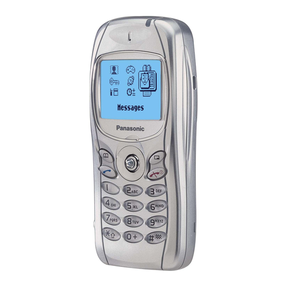
Personal Cellular Phone
EB-GD75
EB-GD75C
Frequency Range
Tx/Rx frequency
separation
RF Channel Bandwidth
Number of RF channels
Speech coding
Operating temperature
Type
RF Output Power
Modulation
Connection
Voice digitizing
Transmission speed
Diversity
Signal Reception
Antenna Impedance
(External Connector)
Antenna VSWR
Dimensions
(excluding antenna)
Volume
Weight
Display
Illumination
Keys
SIM
External DC Supply
Voltage
Battery
Standby Time
Talk Time
Battery life figures are dependent on battery and network conditions, SIM card and usage.
WARNING
© 2001 Matsushita Communication Industrial UK Ltd.
All
rights
distribution is a violation of law.
Order Number: MCUK011201C8
900 MHz
Tx: 880 - 915MHz
Tx: 1710 -1785 MHz
Rx: 925 - 960 MHz
Rx: 1805 -1880 MHz
45 MHz
95 MHz
200 kHz
174
374
Full rate/Half rate/Enhanced Full rate
-10 °C to +55 °C
Class 4 Handheld
Class 1 Handheld
2 W maximum
1 W maximum
GMSK (BT = 0.3)
8 ch / TDMA
13 kbps RPE-LTP / 13 kps ACLEP / 5.6 kps CELP / VSLEP
270.833 kbps
Frequency hopping
Direct conversion
50 τ
< 2.1 : 1
Height: 106 mm
Width:
46 mm
Depth:
16 mm
77 cc
82 g
Graphical chip on glass liquid crystal, Alphanumeric,
16 characters x 3 rows + 2 lines of icons.
1 LED for the LCD
8 LEDs for the keypad (Green)
1 LED Incoming call (Green)
1 Charging LED (Red)
16-key Keypad, Navigation key.
Plug-in type only
5.8 V
3.7 V nominal, 650mAh, Li-Ion
150 hrs maximum
360 minutes maximum
reserved.
Unauthorized
1800 MHz
copying
and
Advertisement
Table of Contents

Related Manuals for Panasonic EB-GD75


Summary of Contents for Panasonic EB-GD75
- Page 1 Order Number: MCUK011201C8 Personal Cellular Phone EB-GD75 EB-GD75C 1800 MHz 900 MHz Frequency Range Tx: 880 - 915MHz Tx: 1710 -1785 MHz Rx: 925 - 960 MHz Rx: 1805 -1880 MHz Tx/Rx frequency 45 MHz 95 MHz separation RF Channel Bandwidth...
-
Page 2: Mcuk011201C8
Every care has been taken to ensure that the contents of this manual give an accurate representation of the equipment. However, Matsushita Communication Industrial UK Ltd. accepts no responsibility for inaccuracies which may occur and reserves the right to make changes to the specification or design without prior notice. The information contained in this manual and all rights in any design disclosed therein, are and remain the exclusive property of Matsushita Communication Industrial UK Ltd. -
Page 3: Mcuk011201C8
They must not be incinerated, or disposed of as ordinary rubbish. 1.1. Purpose of the Manual This Service Manual contains the information and procedures required for installing, operating and servicing the Panasonic GSM Personal Cellular Mobile Telephone system operating on GSM Digital Cellular Networks. -
Page 4: Mcuk011201C8
2.2. Features The Panasonic Telephone Model GD75 is a high performance, small, light, handset for business and domestic use. The following features are provided: Triple Rate, which includes Full Rate, Half rate and Enhanced Full Rate (EFR) speech, codec. -
Page 5: Mcuk011201C8
OPERATING INSTRUCTIONS 3 OPERATING INSTRUCTIONS 3.1. General This section provides a brief guide to the operation and facilities available on the telephone handset. Refer to the Operating Instructions supplied with the telephone for full operational information. 3.2. Liquid Crystal Display The telephone handset has a graphical chip on glass display. -
Page 6: Mcuk011201C8
OPERATING INSTRUCTIONS 3.3. Location of Controls Incoming / Charge indicator: Green - Incoming call. Red - Charging battery pack. External connector: Used to connect to external accessories or to charging equipment. INCOMING CALL / EARPIECE CHARGE INDICATOR DISPLAY NAVIGATION MICROPHONE EARPHONE / MICROPHONE SOCKET EXTERNAL CONNECTOR... -
Page 7: Mcuk011201C8
OPERATING INSTRUCTIONS 3.4. Concept of Operation There is a close relationship between the Select keys, Navigation key and display. Secondary Main Option Area Option Area Select Key Select Key Navigation 10523-1 Figure 3.3: Concept of Operation Pressing up and down ( ) will move the pointer up and down and scroll through more information in the main area of the display. -
Page 8: Mcuk011201C8
OPERATING INSTRUCTIONS 3.5.2 Editing Alpha Entry Pressing will move the cursor up or down one line. Pressing will move the cursor left or right one character. When the cursor is moved over a character and another key pressed this will insert the new character. Pressing will delete the character to the left of the cursor. -
Page 9: Mcuk011201C8
OPERATING INSTRUCTIONS 3.7. Incoming Call Line Identification (CLI) When a call is received the last six digits of the CLI information is matched with the phonebook. Therefore an incoming call could be matched to the wrong phonebook entry. 3.8. Hot Key Dial Source List The source for Hot Key Dial Numbers is normally ‘Phonebook’... -
Page 10: Mcuk011201C8
OPERATING INSTRUCTIONS 3.9.7 Calling Line Identification Feature Service Code Calling Line Identification Presentation (CLIP) Calling Line Identification Restriction (CLIR) Connected Line Presentation (CLOP) Connected Line Restriction (CLOR) Enable * <SERVICE CODE> * # <SND> Disable # <SERVICE CODE> * # <SND> Temporary Suppress Identification # 3 1 # <TELEPHONE NUMBER>... -
Page 11: Mcuk011201C8
OPERATING INSTRUCTIONS 3.9.9 Call Divert Call Divert Type Service Code Divert all calls Divert all calls if busy Divert calls if no reply Divert if not reachable Set (except “No Reply” Call * * <SERVICE CODE> * <FORWARD TELEPHONE NUMBER> * <TELECOMMUNICATION SERVICE>... -
Page 12: Mcuk011201C8
OPERATING INSTRUCTIONS 3.10. Troubleshooting The user is given the following information and advised to contact the dealer if the problems persist: Problem Cause Remedy Telephone will not switch Check that the battery pack is fully charged and correctly connected to the telephone. Extremely short battery The network in use and the condition of the Avoid areas of poor reception. -
Page 13: Mcuk011201C8
OPERATING INSTRUCTIONS 3.11. Important Error Messages The following table is a list of error messages that may occur during use of the telephone, with a description and suggested course of action: Error Message Explanation / Remedy Area not Allowed Roaming in the selected area is not allowed. Network not Allowed Roaming with the selected network is not allowed. -
Page 14: Mcuk011201C8
OPERATING INSTRUCTIONS 3.13. SIM Personalisation 3.13.1 Introduction SIM personalisation will limit the use of the telephone to a single SIM, a SIM supplied by one Network/Sub-network/Service Provider or a SIM purchased by a company (corporation). If a personalised handset contains a SIM that is from a different source, it will display the message “SIM ERROR”... -
Page 15: Issue B Revision
OPERATING INSTRUCTIONS 3.13.5 Enabling Procedure to point at: “SIM” for SIM Personalisation ”Network” for Network Personalisation “Subnetwork” for Subnetwork Personalisation ”SP” for Service Provider Personalisation or ”Corporate” for Company Personalisation. the 16 digit Control Key. the 16 digit Control Key. The display will confirm which type of Personalisation has been enabled. - Page 16 OPERATING INSTRUCTIONS 3.15. GSM Network Codes and Names Access Network Service or Operator Phone Display Band Code Code ALBANIA +355 AMC MOBIL AMC - AL GSM 900 ANDORRA +376 MOBILAND STA-MOBILAND GSM 900 ARMENIA +374 ARMGSM RA-ARMGSM GSM 900 AUSTRALIA MOBILENET TELSTRA GSM 900...
-
Page 17: Mcuk011201C8
OPERATING INSTRUCTIONS Access Network Service or Operator Phone Display Band Code Code HONG_KONG +852 HK SMC HK SMC GSM 900 HK TELECOM CAMPERSANDW HKT GSM 900 NEW WORLD NEW WORLD GSM 1800 Orange Orange GSM 900 P Plus P Plus GSM 1800 P-Link P-Link... -
Page 18: Mcuk011201C8
OPERATING INSTRUCTIONS Access Network Service or Operator Phone Display Band Code Code MOROCCO +212 ONPTGSM MOR ONPT GSM GSM 900 NAMIBIA +264 NAM MTC GSM 900 NETHERLANDS Ben NL Ben NL GSM 1800 KPN TELECOM NL KPN TELECOM GSM 900 LIBERTEL NL LIBERTEL GSM 900... -
Page 19: Mcuk011201C8
OPERATING INSTRUCTIONS Access Network Service or Operator Phone Display Band Code Code TAIWAN +886 Chunghwa Chunghwa GSM 900 Far EasTone Far EasTone GSM 900 KGT-ONLINE KGT-ONLINE GSM 1800 MOBITAI MOBITAI GSM 900 TUNTEX TUNTEX GSM 1800 TWN GSM TWN GSM GSM 1800 TransAsia Telecom GSM TransAsia GSM... -
Page 20: Mcuk011201C8
OPERATING INSTRUCTIONS 3.16. Glossary of Terms Term Definition DTMF Dual Tone Multiple Frequency tones. The numeric keys 0 to 9, and * and # will generate different DTMF tones when pressed during conversation. These are used to access voice mail, paging and home banking services. -
Page 21: Mcuk011201C8
DISASSEMBLY / REASSEMBLY INSTRUCTIONS 4 DISASSEMBLY / REASSEMBLY INSTRUCTIONS General 4.1. This section provides disassembly and reassembly procedures for the main components of the telephone. These assemblies MUST be performed by qualified service personnel at an authorised service centre. The following Warnings and Cautions MUST be observed during all disassembly / reassembly operations: WARNING The equipment described in this manual contains polarised capacitors utilising liquid electrolyte. -
Page 22: Mcuk011201C8
DISASSEMBLY / REASSEMBLY INSTRUCTIONS Remove the two case screws located inside the battery compartment. 10504-1 Figure 4.2: Case Screw Removal Carefully prise apart the case and cover, creating a gap at the base I/O connector. Insert the Case Separation Tool (see Section 6) into the gap created, and gently slide the tool in the direction shown, ensuring that the moulded hooks separate all the way up to point ‘A’. -
Page 23: Mcuk011201C8
DISASSEMBLY / REASSEMBLY INSTRUCTIONS 1. Using a small screwdriver blade or similar blunt object, depress one of the RF Shield lugs (marked ‘A’ and ‘B’ in the diagram below) to release the PCB from the case. 10507-1 Figure 4.4: PCB Assembly Removal 4.2.2 LCD Removal Gently prise apart the two ears of the metal snap (marked ‘A’... -
Page 24: Mcuk011201C8
DISASSEMBLY / REASSEMBLY INSTRUCTIONS Using a small screwdriver blade or similar instrument on one corner of the LCD (connector end), carefully lift the LCD from its LCD Holder. 10538-1 Figure 4.7: Removing the LCD from its Holder The LCD connector strip (‘Zebra strip’) can be removed from the LCD Holder using a pair of tweezers. 4.2.3 Case-Mounted Components Remove the keypad by pressing on the navigation key until the membrane can be peeled away from the case front. -
Page 25: Mcuk011201C8
DISASSEMBLY / REASSEMBLY INSTRUCTIONS To remove the speaker (receiver), first remove the retaining clip. Then lift the speaker from the case by inserting a small screwdriver blade or similar blunt object underneath it. 10471-1 Figure 4.10: Speaker (Receiver) Removal Lift the DTHF speaker from the case by inserting a small screwdriver blade or similar blunt object underneath it. 10501-1 Figure 4.11: DTHF Speaker Removal The Vibrate motor may be lifted from the case by gently applying pressure under the spindle / counterweight. -
Page 26: Mcuk011201C8
DISASSEMBLY / REASSEMBLY INSTRUCTIONS Using a small screwdriver blade or similar blunt object as a lever, lift the internal antenna assembly from the case. 10503-1 Figure 4.13: Antenna Removal 4.3. Reassembly Reassembly is the reverse of disassembly. Ensure that the metal spring inside the Front Cover is not damaged or bent. Replace the complete Cover Assembly if necessary. -
Page 27: Mcuk011201C8
TECHNICAL SPECIFICATIONS 5 TECHNICAL SPECIFICATIONS 5.1. Tx Characteristics All data is applicable to E-GSM 900 and GSM 1800 except where stated. 5.1.1 Frequency Error ±0.1 ppm max., relative to base station frequency. 5.1.2 Modulation Phase Error RMS: Equal to or less than 5 ° Peak Equal to or less than 20 °... -
Page 28: Mcuk011201C8
TECHNICAL SPECIFICATIONS 5.1.5 Spurious Emissions at Antenna Connector Limits (dBm) Frequency Filter Approx. Frequency Range Offset Bandwidth Video B/W E-GSM 900 GSM 1800 30 to 50 MHz 10 kHz 30 kHz 50 to 500 MHz 100 kHz 300 kHz 500 MHz to 1GHz 0 to 1 MHz 100 kHz 300 kHz... -
Page 29: Mcuk011201C8
TECHNICAL SPECIFICATIONS E-GSM 900 Half Rate Speech The reference sensitivity performance in terms of frame erasure, bit error, or residual bit error rates (whichever is appropriate) is specified in the following table, according to the propagation conditions. Propogation Conditions Propogation Conditions Propogation Conditions Channels TUhigh... -
Page 30: Mcuk011201C8
TECHNICAL SPECIFICATIONS Blocking: Small MS level in dBµVemf() Frequency E-GSM 900 GSM 1800 FR 600 kHz to FR 800 kHz FR 800 kHz to FR 1.6 MHz FR 1.6 MHz to FR 3 MHz 915 MHz to FR -3 MHz FR 3 MHz to FR 980 MHz FR 600 kHz to FR 800 kHz 1785 MHz to FR - 3 MHz... -
Page 31: Mcuk011201C8
TEST AND MEASUREMENT 6 TEST AND MEASUREMENT 6.1. Introduction This section provides information on testing the telephone. The layout is as follows: Section 6.2: Handling and repair of Any-Layer Interstitial Via Hole (ALIVH) PCBs. Section 6.3 External testing: describes equipment requirements and general set up procedure. Section 6.4 Complete Unit Test Setup: describes how the items of test equipment are used together and general set up procedure. -
Page 32: Mcuk011201C8
TEST AND MEASUREMENT Hot-Air Blower The blower air temperature should be at: 295 °C ±5 °C for an application time of 120 seconds or less, 395 °C ±5 °C for an application time of 30 seconds or less. Removal and re-mounting of components should be performed only once at any component position. Note: To avoid land detachment, do NOT apply excessive force on the soldering iron when heating the board. -
Page 33: Mcuk011201C8
TEST AND MEASUREMENT 4 . 8 . 2 8 FRONT REAR 10016-1 Figure 6.1: Interface Box IFB003 / IFB004 Personal Computer (PC) The PC (IBM compatible) is used as a Unit Under Test controller. This in conjunction with the channel box software, allows all of the test facilities normally provided through the keypad of the Unit Under Test. -
Page 34: Mcuk011201C8
TEST AND MEASUREMENT GSM Tester This unit acts as a base station providing all the necessary GSM signalling requirements and also provides GSM signal measuring facilities. Dummy Battery (Part No. JT00073) The dummy battery is used for battery calibration. 10532-1 Figure 6.4: Dummy Battery Channel Box Software This is the test software for the telephone unit and should be installed onto the personal computer to be used for testing. -
Page 35: Mcuk011201C8
TEST AND MEASUREMENT 6.4. Complete Unit Setup 6.4.1 Connection Diagrams INTERFACE BOX +12V POWER SUPPLY RS232 GSM TESTER PCB REPAIR JIG RF CABLE PCB TEST SETUP INTERFACE BOX +12V POWER SUPPLY RS232 RF ADAPTOR GSM TESTER RF CABLE UNIT UNDER TEST COMPLETE UNIT TEST SETUP 10516-1 Figure 6.6: Test Connection Diagrams... -
Page 36: Mcuk011201C8
RF Adaptor Interface Cable JT00043 Panasonic Channel Box software for Microsoft Windows®. The Channel Box software should be installed onto the main drive of the personal computer. The RF cable is connected to the GSM test station via a suitable adaptor. The 12 V supply is connected to the rear socket of the Interface box. -
Page 37: Mcuk011201C8
Check that the handset is powered-up (LCD is backlit and all LEDs are on). The Channel Box should also display handset IMEI number and Firmware version information in the left-hand column of the screen. A toolbar should also be visible in the top panel where the Panasonic logo is displayed. Figure 6.9: Channel Box Toolbar Additional user instructions are provided in the help file supplied with the Channel Box. -
Page 38: Mcuk011201C8
ADJUSTMENT PROCEDURES 7 ADJUSTMENT PROCEDURES 7.1. RF Calibration Procedure NOTE: See Section 6.2 for a list of the equipment and setup procedures required to perform the following adjustment and calibration procedures. The following procedures MUST be performed after replacement or repair of the PCB. Failure to do so may result in incorrect operation of the telephone. -
Page 39: Mcuk011201C8
7.2.3 Power Level Calibration NOTE: To ensure that the telephone operates within set SAR margins, Panasonic recommends that a power meter capable of measurement to an accuracy of ±0.2 dB is used when calibrating power levels. Use of a less accurate power meter may result in the telephone failing to meet SAR standards. -
Page 40: Mcuk011201C8
ADJUSTMENT PROCEDURES Click the NEXT CAL button. Repeat steps 3, 4 and 5 until the NEXT CAL button is greyed out (i.e. cannot be selected). Click on the EXIT button when finished. 7.3. RSSI This procedure describes the calibration of RSSI on the mid-channel. This procedure must also be carried out for the low / bottom channel and high / top channel. -
Page 41: Mcuk011201C8
ADJUSTMENT PROCEDURES 7.4. Battery Calibration 7.4.1 Preliminaries There are three procedures to calibrating the battery, voltage, temperature and charging calibration. A Battery Calibration Voltage Control Unit (BCVCU) is used to provide the necessary voltage levels for these checks. The BCVCU replaces the two regulated power supplies and 82 Ohm resistor required to caibrate previous mobile products. -
Page 42: Mcuk011201C8
ADJUSTMENT PROCEDURES The Battery Calibration window is divided into three areas, Voltage Calibration, Temperature calibration and Charging calibration. The Voltage calibration area is sub-divided into Semi-Automatic and Manual areas 7.4.2 Voltage Calibration Semi-automatic calibration only: Carry out the instructions as detailed in the window, clicking the CAL V Hi and CAL V Lo buttons when instructed. -
Page 43: Mcuk011201C8
ADJUSTMENT PROCEDURES Automatic calibration only: Click on the READ_Hi button to check the BAT VOLT HIGH reading. Set the value using the ‘spinners’ ( arrows) or type in the value directly. Click on the APPLY button to set the BAT VOLT HIGH value. Repeat steps a) t o c), clicking the READ_LO button to check the BAT VOLT LOW reading. -
Page 44: Mcuk011201C8
ADJUSTMENT PROCEDURES 7.4.3 Temperature Calibration Ensure that VBAT is set to 4.1 V. Carry out the instructions described in the main dialogue window. Issue B Section 7 MCUK011201C8 Revision 0 – 42 – Service Manual... -
Page 45: Mcuk011201C8
ADJUSTMENT PROCEDURES 7.4.4 Charging Calibration On the Interface Box, ensure that the EXT PWR switch is ON. Check that the BCVCU 82 Ohms switch is set to ON. Carry out the instructions described in the main dialogue window. MCUK011201C8 Section 7 Issue B Service Manual –... -
Page 46: Mcuk011201C8
REPLACEMENT PARTS LIST 8 REPLACEMENT PARTS LIST 8.1. Case and Cover Parts 10515-1 Figure 8.1: Case and Cover Parts Ref. No. Part No. Part Name & Description Ref. No. Part No. Part Name & Description 2RA648A RECEIVER HOLDER GD95 GD75CVR01S GD75 COVER SILVER (SERVICE) 2EA634A LCD PANEL GD75 SILVER... -
Page 47: Mcuk011201C8
PCB ASSY LANGUAGE PACK B GD75BRD001C PCB ASSY LANGUAGE PACK C GD75BRD001D PCB ASSY LANGUAGE PACK D Network-specific (SIM-locked) PCB Assemblies are available - please refer to Panasonic spares representative for details. MCUK011201C8 Section 8 Issue B Service Manual – 45 –... -
Page 48: Mcuk011201C8
REPLACEMENT PARTS LIST 8.4. PCB Components Ref. No. Part No. Part Name & Description Grid C407 ECJ0EC1H100D CAP CER 10pF +/-0.5pF 50V NP0 C454 F1G1H101A422 CAP CER 100pF 5% 50V NP0 C455 F1G1H102A457 CAP CER 1nF 10% 50V X7R Ref. No. Part No. -
Page 49: Mcuk011201C8
REPLACEMENT PARTS LIST Ref. No. Part No. Part Name & Description Grid Ref. No. Part No. Part Name & Description Grid C834 F1G1A104A012 CAP CER 100nF 10% 10V X5R L113 G1C15NG00009 INDUCTOR 15nH 2% C834 F1G1H470A422 CAP CER 47pF 50V 5% NP0 L202 ELJRF5N6JF2 INDUCTOR 5.6nH 5%... -
Page 50: Replacement Parts List
REPLACEMENT PARTS LIST 8.5. Refurbishment Kits Ref. No. Part No. Part Name & Description Grid R609 ERJ2GEJ223X RES 22K OHM 5% 1/16W R610 ERJ2GEJ104X RES 100K OHM 5% 1/16W R611 ERJ2GEJ224X RES 220K OHM 5% 1/16W Ref. No. Part No. Part Name &... -
Page 51: Circuit Diagrams
CIRCUIT DIAGRAMS 9 CIRCUIT DIAGRAMS Figure 9.1: GD75 Circuit Diagram - RF MCUK011201C8 Section 9 Issue B Service Manual – 49 – Revision 0... - Page 52 CIRCUIT DIAGRAMS Figure 9.2: GD75 Circuit Diagram - Logic Issue B Section 9 MCUK011201C8 Revision 0 – 50 – Service Manual...
-
Page 53: Layout Diagrams
LAYOUT DIAGRAMS 10 LAYOUT DIAGRAMS Figure 10.1: PCB Layout - Side 1 MCUK011201C8 Section 9 Issue B Service Manual – 51 – Revision 0... - Page 54 LAYOUT DIAGRAMS Figure 10.2: PCB Layout - Side 2 MCUK011201C8 Section 9 Issue B Service Manual – 52 – Revision 0...