Panasonic HDC-HS300P Service Manual
High definition
Hide thumbs
Also See for HDC-HS300P:
- Operating instructions manual (183 pages) ,
- Operating instructions manual (172 pages)
Table of Contents
Advertisement
Quick Links
4
High Definition Video Camera
HDC-HS300P
Model No.
HDC-HS300PC
HDC-HS300EB
HDC-HS300EC
HDC-HS300EE
HDC-HS300EF
HDC-HS300EG
HDC-HS300EP
HDC-HS300GC
HDC-HS300GK
HDC-HS300GT
HDC-HS300SG
Vol. 1
Colour
(K)...........Black Type
(S)...........Silver Type (only GC)
© Panasonic Corporation 2009. Unauthorized copy-
ing and distribution is a violation of law.
ORDER NO. VM0902007CE
B27
Advertisement
Chapters
Table of Contents

Related Manuals for Panasonic HDC-HS300P


Summary of Contents for Panasonic HDC-HS300P
- Page 1 High Definition Video Camera HDC-HS300P Model No. HDC-HS300PC HDC-HS300EB HDC-HS300EC HDC-HS300EE HDC-HS300EF HDC-HS300EG HDC-HS300EP HDC-HS300GC HDC-HS300GK HDC-HS300GT HDC-HS300SG Vol. 1 Colour (K)...Black Type (S)...Silver Type (only GC) © Panasonic Corporation 2009. Unauthorized copy- ing and distribution is a violation of law.
-
Page 2: Table Of Contents
TABLE OF CONTENTS PAGE PAGE 1 Safety Precaution -------------------------------------------------3 1.1. General Guidelines ----------------------------------------3 1.2. Leakage Current Cold Check ---------------------------3 1.3. Leakage Current Hot Check (See Figure 1.)--------3 1.4. How to Discharge the Capacitor on Sub PCB ------4 2 Warning --------------------------------------------------------------5 2.1. -
Page 3: Safety Precaution
1 Safety Precaution 1.1. General Guidelines 1.3. Leakage Current Hot Check (See Figure 1.) 1. IMPORTANT SAFETY NOTICE There are special components used in this equipment 1. Plug the AC cord directly into the AC outlet. Do not use which are important for safety. These parts are marked by an isolation transformer for this check. -
Page 4: How To Discharge The Capacitor On Sub Pcb
1.4. How to Discharge the Capacitor on Sub PCB CAUTION: 1. Be sure to discharge the capacitor on SUB PCB. 2. Be careful of the high voltage circuit on SUB PCB when servicing. [Discharging Procedure] 1. Refer to the disassemble procedure and Remove the necessary parts/unit. 2. -
Page 5: Warning
2 Warning 2.1. Prevention of Electrostatic Discharge (ESD) to Electrostatically Sensitive (ES) Devices Some semiconductor (solid state) devices can be damaged easily by static electricity. Such components commonly are called Elec- trostatically Sensitive (ES) Devices. Examples of typical ES devices are integrated circuits and some field-effect transistors and semiconductor "chip"... -
Page 6: Caution For Ac Cord (For Eb/Gc
2.3.2.3. How to Replace the Fuse A replacement fuse cover can be purchased from your local Panasonic Dealer. 1. Remove the Fuse Cover with a screwdriver. If the fitted moulded plug is unsuitable for the socket outlet in your home then the fuse should be removed and the plug cut off and disposed of safety. -
Page 7: How To Replace The Lithium Battery
It should be disposed of in waste products destined for burial rather than incineration. NOTE: Above caution is applicable for a battery pack which is for HDC-HS300 series, as well. 1. Battery Pack for this model. 2. Button-type battery for Remote controller (CR2025: Being supplied from Energy Company, Panasonic Corporation) -
Page 8: Service Navigation
When a part replacement is required for repairing MAIN PCB, replace as an assembled parts. (Main PCB) 2. The following category is /are recycle module part. Please send it/them to Central Repair Center. • MAIN PCB (VEP03H66AR : HDC-HS300P/PC) • MAIN PCB (VEP03H66AW : HDC-HS300EB) •... -
Page 9: How To Define The Model Suffix (Ntsc Or Pal Model)
3.4. How to Define the Model Suffix (NTSC or PAL model) There are eight kinds of HDC-HS300. • a) HDC-HS300S • b) HDC-HS300P • c) HDC-HS300PC • d) HDC-HS300EB/EC/EF/EG/EP • e) HDC-HS300EE • f) HDC-HS300GK • g) HDC-HS300GT • h) HDC-HS300GC/SG (HDC-HS300S is exclusively Japan domestic model.) -
Page 10: Precautions For Handling Hdd
3.5. Precautions for Handling HDD 1. Handle HDD very carefully to prevent the static electricity and shock. 2. Set the HDD quickly after taking it out from the package. Make sure to put the HDD on buffer materials, etc. 3.5.1. Precautions at incoming process and for opening packages... - Page 11 3.5.2. Precautions for installing HDD...
- Page 12 3.5.3. Precautions for inserting and removing HDD FPC Make sure to use the tool (LSVQ0112) when locking and unlocking the lock lever of HDD FPC connector. Do not lock the lock lever without inserting HDD FPC. Otherwise, the connector may be damaged.
-
Page 13: Formatting Hdd
Make sure to use the tool (LSVQ0112) when opening and closing the lock lever. When install the HDD to main unit, necessary install the HDD FPC and HDD cushion. 3.6. Formatting HDD When HDD is exchanged, format HDD as the procedure below... -
Page 14: Specifications
4 Specifications... -
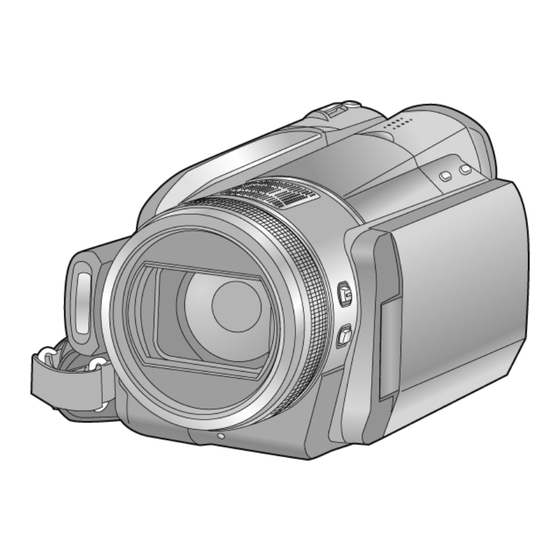
Page 17: Location Of Controls And Components
Eyepiece corrector dial Battery holder DC input terminal [DC IN] Always use the supplied AC adaptor or a ● genuine Panasonic AC adaptor (VW-AD21PP; optional). It can open up to 90 . USB terminal [ ● 10 Quick menu button [Q.MENU]... - Page 18 23 24 31 Built-in flash 32 Lens (LEICA DICOMAR) 22 Lens cover 33 Lens hood The lens cover opens in Motion Picture ● Rotate the lens hood counter-clockwise Recording Mode or Still Picture Recording remove it. In order to attach it, place into slot Mode.
- Page 19 39 40 35 Recording start/stop button 45 Shoulder strap fixture 36 HDD access lamp [ACCESS HDD] 37 Viewfinder Due to limitations in LCD production technology, there may be some tiny bright or dark spots on the viewfinder screen. However, this is not a malfunction and does not affect the recorded picture.
-
Page 20: Selecting A Mode
Selecting a mode (Turning the unit on/off) Change the mode to recording, playback or power OFF. Turn on the power by changing the mode to while pressing the lock release button Rotate the mode dial while at the same ● time pressing in the lock release button if changing from OFF to another mode. -
Page 21: How To Use The Touch Screen
How to use the touch screen You can operate by directly touching the LCD monitor (touch screen) with your finger. It is easier to use the stylus pen (supplied) for detailed operation, or if it is hard to operate with your fingers. Touch About the operation icons Touch and release the touch screen to select... -
Page 22: Using With The Remote Control
[Excluding skip playback]. Delete button [ Direction buttons [ , , , ] Replace battery with Panasonic PART NO. Zoom/volume/thumbnail display switch CR2025 only. Use of another battery may buttons [T, W, /VOL]* present a risk of fire or explosion. -
Page 23: Service Mode
6 Service Mode 1. Indication method of the service menu Set the mode dial “Motion Picture Recording” mode. 2. While keep pressing the “Intelligent auto” button, “Manual focus” button and “Menu” button for more than 3 seconds until the top screen of the Service Mode Menu being displayed. Service mode menu Screen display Contents... -
Page 24: Drive Information Display
6.1. Drive Information Display 1. Set the mode dial “Motion Picture Recording” mode. 2. While keep pressing the “Intelligent auto” button, “Manual focus” button and “Menu” button for more than 3 seconds until the top screen of the Service Mode Menu being displayed. 3. -
Page 25: Hdd Self Check Execution
6.2. HDD Self Check Execution 1. Set the mode dial “Motion Picture Recording” mode. 2. While keep pressing the “Intelligent auto” button, “Manual focus” button and “Menu” button for more than 3 seconds until the top screen of the Service Mode Menu being displayed. 3. -
Page 26: Lock Search History Indication
6.3. Lock Search History Indication 1. Set the mode dial “Motion Picture Recording” mode. 2. While keep pressing the “Intelligent auto” button, “Manual focus” button and “Menu” button for more than 3 seconds until the top screen of the Service Mode Menu being displayed. 3. -
Page 27: Power On Self Check Result Display
6.4. Power ON Self Check Result Display 1. Set the mode dial “Motion Picture Recording” mode. 2. While keep pressing the “Intelligent auto” button, “Manual focus” button and “Menu” button for more than 3 seconds until the top screen of the Service Mode Menu being displayed. 3. -
Page 28: Hdd Hardware Test
6.5. HDD Hardware Test 1. Set the mode dial “Motion Picture Recording” mode. 2. While keep pressing the “Intelligent auto” button, “Manual focus” button and “Menu” button for more than 3 seconds until the top screen of the Service Mode Menu being displayed. 3. -
Page 29: Disassembly And Assembly Instructions
7 Disassembly and Assembly Instructions 7.1. Disassembly Flow Chart 7.2. PCB Location... -
Page 30: Disassembly Procedure
7.3. Disassembly Procedure Item Removal LCD Unit Fig.D17 2 Screws (S) Item Removal Hinge Support Plate Lens Hood Fig.D1 Lens Hood SR Earth Board (B) Side Case (R) Unit Fig.D2 1 Screw (A) LCD Detection Lever 4 Screws (B) 2 Locking tabs 1 Screw (C) LCD Unit 3 Screws (D) - Page 31 Item Removal Fig.D30 1 Screw (c) 1 Screw (d) Front Angle Top Fig.D31 Front Ornament Mic Cushion (A) Mic Cushion (B) Mic Cushion (C) Power FPC Fig.D32 Battery Terminal Barrier 2 Screws (e) 1 Screw (f) Rear Frame B 1 Screw (g) Rear Frame A 2 Locking tabs Power FPC...
- Page 32 7.3.2. Removal of the Side Case (R) Unit Fig.D3 7.3.3. Removal of the Side Case (L) Unit Fig.D2 Fig.D4...
- Page 33 7.3.4. Removal of the HDD Unit 7.3.5. Removal of the Top Case Unit Fig.D5 Fig.D6...
- Page 34 Fig.D7 Fig.D9 7.3.6. Removal of the Side (L) P.C.B. and 7.3.7. Removal of the Front Case Unit Battery Case Unit Fig.D10 Fig.D8...
- Page 35 Fig.D11 7.3.8. Removal of the Lens Unit Fig.D13 7.3.9. Removal of the Main P.C.B. Fig.D14 Fig.D12...
- Page 36 7.3.10. Removal of the Sub P.C.B. 7.3.11. Removal of the Side (R) P.C.B. and Cooling Fan Motor Fig.D15 Fig.D16...
- Page 37 7.3.12. Removal of the LCD Unit 7.3.13. Removal of the LCD Hinge Unit Fig.D18 7.3.14. Removal of the LCD OP Button Unit Fig.D17 Fig.D19...
- Page 38 Fig.D20 7.3.15. Removal of the Monitor P.C.B. Fig.D22 Fig.D21...
- Page 39 7.3.16. Removal of the LCD 7.3.17. Removal of the Front P.C.B. Fig.D23 Fig.D24...
- Page 40 7.3.18. Removal of the Camera Operation 7.3.19. Removal of the Barrier Motor Unit Unit Fig.D25 Fig.D26...
- Page 41 7.3.20. Removal of the Barrier Unit and MF Ring Ornament Fig.D27 Fig.D28...
- Page 42 7.3.21. Removal of the Flash Unit Fig.D29 7.3.22. Removal of the ECM Fig.D31 Fig.D30...
- Page 43 7.3.23. Removal of the Power FPC 7.3.24. Removal of the EVF Unit Fig.D33 7.3.25. Removal of the Operation Button Unit and Top Case Unit Fig.D34 Fig.D32...
- Page 44 7.3.26. Removal of the Speaker 7.3.27. Removal of the Shoe Angle and Grip Ornament Fig.D35 Fig.D36...
- Page 45 7.3.29. Removal of the Zoom Motor Fig.D37 7.3.28. Removal of the MOS Unit and Optical Filter Fig.D39 Fig.D38...
- Page 46 7.3.31. Removal of the Main Frame Unit and 2nd Lens Frame Move Unit Fig.D42 7.3.32. Removal of the 2nd Lens Frame Spring and OIS/IRIS Unit Fig.D40 7.3.30. Removal of the 1st Lens Frame Move Unit Fig.D43 Fig.D41...
- Page 47 7.3.33. Removal of the IRIS Unit 7.3.34. Removal of the Master Flange Unit and 4th Lens Frame Move Unit Fig.D44 Fig.D45...
-
Page 48: Measurements And Adjustments
8 Measurements and Adjustments 8.1. Electric Adjustment • Adjustment method is different from a conventional SD video camera. • An exclusive jig and PC (including software for adjustment “Tatsujin”) are necessary for electric adjustment. • A USB driver for service is necessary to communication with PC. •... - Page 49 Adjustment Items • Adjustment item as follows. The adjustment instruction is available at "Software download" on the "Support Information from NWBG/VDBG-AVC" web-site in "TSN System".
-
Page 50: Factory Setting
9 Factory Setting 9.1. HOW TO TURN ON THE FACTORY SETTINGS? 1. Set the mode dial “Motion Picture Recording” mode. 2. While keep pressing the “Intelligent auto” button, “Manual focus” button and “Menu” button for more than 3 seconds until the top screen of the Service Mode Menu being displayed. -
Page 51: What Is The Factory Settings
9.2. WHAT IS THE FACTORY SETTINGS? The factory settings clean up and/or refresh the following settings. 1. MENU, MODE, ADJUSTMENT VALUE. 2. SD card format. 3. Reset the folder number and file number of still pictures. (Setting the folder number is 100, and file number is 0.) 4. - Page 52 HDC-HS300EC HDC-HS300GK HDC-HS300EE HDC-HS300GT 5.The voltage being indicated here may be include observational-error (deviation) due to HDC-HS300EF HDC-HS300P internal-resistance and/or reactance of equipment. Therefore, handle the value indicated on here as reference. HDC-HS300EG HDC-HS300PC HDC-HS300EP HDC-HS300SG 6.Use the parts number indicated on the Replacement Parts List .
-
Page 53: S2. Block Diagram
S2. Block Diagram S2.1. Overall Block Diagram IC601 COLOR LCD PANEL DRIVER LENS(F1.8 x 12) IC851 ZOOM/ 3MOS IRIS/ FOCUS DRIVER MOTOR A/V OUT IC3601 D TERMINAL VIDEO ENCODER IC4801-4803 MIC AMP IC3701 AVIO Q4901-4904,4907, EXT. MIC 4908/QR4901 MIC AMP X301 HEADPHONES IC301... -
Page 54: S3. Schematic Diagram
S3. Schematic Diagram S3.1. Interconnection Diagram FP801 REAR OPERATION EVF FPC EVF B/L P.C.B. (FOIL SIDE) PS851 SIDE-L P.C.B. FP6004 (FOIL SIDE) G EXTMICL G EXTMICL G EXTMICR EXTMIC L G HPR G HPL (COMPONENT SIDE) HP DET L MFL2 MFL1 PS6011 KEYIN4... -
Page 55: S3.2. Side R Schematic Diagram
S3.2. Side R Schematic Diagram HDC-HS300 Series Side R Section (Side R P.C.B.(1/2)) Schematic Diagram... -
Page 56: S3.3. Lcd Schematic Diagram
S3.3. LCD Schematic Diagram HDC-HS300 Series LCD Section (Side R P.C.B.(2/2)) Schematic Diagram... -
Page 57: S3.4. Monitor Schematic Diagram
S3.4. Monitor Schematic Diagram HDC-HS300 Series Monitor Section (Monitor P.C.B.(1/2)) Schematic Diagram... -
Page 58: S3.5. Tpanel Schematic Diagram
S3.5. TPANEL Schematic Diagram HDC-HS300 Series TPANEL Section (Monitor P.C.B.(2/2)) Schematic Diagram... -
Page 59: S3.6. Side L Schematic Diagram
S3.6. Side L Schematic Diagram HDC-HS300 Series Side L Schematic Diagram... -
Page 60: S3.7. Evf B/L Schematic Diagram
S3.7. EVF B/L Schematic Diagram HDC-HS300 Series EVF B/L Schematic Diagram... -
Page 61: S3.8. Front Schematic Diagram
S3.8. Front Schematic Diagram HDC-HS300 Series Front Schematic Diagram S-10... - Page 62 HDC-HS300 Series Front Schematic Diagram S-11 S-11...
- Page 63 HDC-HS300 Series Front Schematic Diagram S-12...
- Page 64 HDC-HS300 Series Front Schematic Diagram S-13...
-
Page 65: S3.9. Mos Fpc Schematic Diagram
S3.9. MOS FPC Schematic Diagram HDC-HS300 Series MOS FPC Schematic Diagram S-14... -
Page 66: S3.10. Cam Func Op Fpc Schematic Diagram
S3.10. CAM FUNC OP FPC Schematic Diagram / S3.11. Power FPC Schematic Diagram HDC-HS300 Series HDC-HS300 Series CAM FUNC OP FPC Power FPC Schematic Diagram Schematic Diagram S-15... -
Page 67: S3.12. Main Sub Schematic Diagram
S3.12. Main Sub Schematic Diagram HDC-HS300 Series Main Sub Schematic Diagram S-16... -
Page 68: S3.13. Side R Fpc Schematic Diagram
S3.13. Side R FPC Schematic Diagram HDC-HS300 Series Side R FPC Schematic Diagram S-17... -
Page 69: S3.14. Lcd Op Fpc Schematic Diagram
S3.14. LCD OP FPC Schematic Diagram / S3.15. EVF FPC Schematic Diagram HDC-HS300 Series HDC-HS300 Series LCD OP FPC EVF FPC Schematic Diagram Schematic Diagram S-18... -
Page 70: S3.16. Mf Sensor Fpc Schematic Diagram
S3.16. MF Sensor FPC Schematic Diagram / S3.17. HDD FPC Schematic Diagram HDC-HS300 Series HDC-HS300 Series MF Sensor FPC HDD FPC Schematic Diagram Schematic Diagram S-19... -
Page 71: S3.18. Front Fpc Schematic Diagram
S3.18. Front FPC Schematic Diagram HDC-HS300 Series Front FPC Schematic Diagram S-20... -
Page 72: S4. Print Circuit Board
S4. Print Circuit Board S4.1. Side R P.C.B. (Component Side) (Foil Side) HDC-HS300 Series Side R P.C.B. S-21... -
Page 73: S4.2. Monitor P.c.b
S4.2. Monitor P.C.B. S4.2.1. Monitor P.C.B. (Component Side) (Component Side) HDC-HS300 Series Monitor P.C.B. (Component Side) S-22... -
Page 74: S4.2.2. Monitor P.c.b. (Foil Side
S4.2.2. Monitor P.C.B. (Foil Side) (Foil Side) HDC-HS300 Series Monitor P.C.B. (Foil Side) S-23... -
Page 75: S4.3. Side L P.c.b
S4.3. Side L P.C.B. (Component Side) (Foil Side) HDC-HS300 Series Side L P.C.B. S-24... -
Page 76: S4.4. Evf B/L P.c.b
S4.4. EVF B/L P.C.B. (Component Side) (Foil Side) HDC-HS300 Series EVF B/L P.C.B. S-25... -
Page 77: S4.5. Front P.c.b
S4.5. Front P.C.B. (Component Side) (Foil Side) HDC-HS300 Series Front P.C.B. S-26... -
Page 78: S4.6. Mos Fpc P.c.b
S4.6. MOS FPC P.C.B. (Component Side) (Foil Side) HDC-HS300 Series MOS FPC P.C.B. S-27... -
Page 79: S4.7. Cam Func Op Fpc P.c.b
S4.7. CAM FUNC OP FPC P.C.B. (Foil Side) HDC-HS300 Series CAM FUNC OP FPC P.C.B. S-28... -
Page 80: S4.8. Power Fpc P.c.b
S4.8. Power FPC P.C.B. (Component Side) (Foil Side) HDC-HS300 Series Power FPC P.C.B. S-29... -
Page 81: S4.9. Main Sub P.c.b
S4.9. Main Sub P.C.B. (Component Side) (Foil Side) HDC-HS300 Series Main Sub P.C.B. S-30... -
Page 82: S4.10. Side R Fpc P.c.b
S4.10. Side R FPC P.C.B. (Foil Side) HDC-HS300 Series Side R FPC P.C.B. S-31... -
Page 83: S4.11. Lcd Op Fpc P.c.b
S4.11. LCD OP FPC P.C.B. (Foil Side) HDC-HS300 Series LCD OP FPC P.C.B. S-32... -
Page 84: S4.12. Evf Fpc P.c.b
S4.12. EVF FPC P.C.B. (Foil Side) HDC-HS300 Series EVF FPC P.C.B. S-33... -
Page 85: S4.13. Mf Sensor Fpc P.c.b
S4.13. MF Sensor FPC P.C.B. (Component Side) (Foil Side) HDC-HS300 Series MF Sensor FPC P.C.B. S-34... -
Page 86: S4.14. Hdd Fpc P.c.b
S4.14. HDD FPC P.C.B. S4.14.1. HDD FPC P.C.B. (Component Side) (Component Side) HDC-HS300 Series HDD FPC P.C.B. (Component Side) S-35... -
Page 87: S4.14.2. Hdd Fpc P.c.b. (Foil Side
S4.14.2. HDD FPC P.C.B. (Foil Side) (Foil Side) HDC-HS300 Series HDD FPC P.C.B. (Foil Side) S-36... -
Page 88: S4.15. Front Fpc P.c.b
S4.15. Front FPC P.C.B. (Foil Side) HDC-HS300 Series Front FPC P.C.B. S-37... - Page 89 S-38...
-
Page 90: S5. Replacement Parts List
S5. Replacement Parts List Note: 1.* Be sure to make your orders of replacement parts according to this list. 2. IMPORTANT SAFETY NOTICE Components identified with the mark have the special characteristics for safety. When replacing any of these components, use only the same type. 3. - Page 91 HDC-HS300EB/EC/EE/EF/EG/EP/GC/GK/GT/P/PC/SG vol.1 Ref.No. Part No. Part Name & Description Remarks Ref.No. Part No. Part Name & Description Remarks VEP03H66AR MAIN PCB UNIT 1 (RTL) E.S.D. P,PC VEP03H66AW MAIN PCB UNIT 1 (RTL) E.S.D. EB VEP26321A MONITOR PCB (RTL) E.S.D. VEP03H66AU MAIN PCB UNIT 1 (RTL) E.S.D.
- Page 92 HDC-HS300EB/EC/EE/EF/EG/EP/GC/GK/GT/P/PC/SG vol.1 Ref.No. Part No. Part Name & Description Remarks Ref.No. Part No. Part Name & Description Remarks C4909 F1G0J1050007 C.CAPACITOR CH 6.3V 1U VEP20C42A SIDE L PCB UNIT (RTL) E.S.D. C4910 F3F0J226A032 T.CAPACITOR CH 6.3V 22U C4913 F1H0J475A010 C.CAPACITOR CH 6.3V 4.7U C851 F1G1C104A080 C.CAPACITOR CH 16V 0.1U C6401...
- Page 93 HDC-HS300EB/EC/EE/EF/EG/EP/GC/GK/GT/P/PC/SG vol.1 Ref.No. Part No. Part Name & Description Remarks Ref.No. Part No. Part Name & Description Remarks R4907 ERJ6GEYJ154V M.RESISTOR CH 1/8W 150K R4908 ERJ6GEYJ563 M.RESISTOR CH 1/8W 56K VEP20C52A CAM FUNC FPC UNIT (RTL) R4909 ERJ2GEJ102X M.RESISTOR CH 1/16W 1K R4910 ERJ2GEJ562 M.RESISTOR CH 1/16W 5.6K...
- Page 94 HDC-HS300EB/EC/EE/EF/EG/EP/GC/GK/GT/P/PC/SG vol.1 Ref.No. Part No. Part Name & Description Remarks Ref.No. Part No. Part Name & Description Remarks VEP20C42A SIDE L PCB UNIT 1 (RTL) E.S.D. XQN16+B4FJK SCREW VMG1838 HDD CUSHION XQN16+B4FJK SCREW VMG1838 HDD CUSHION XQN16+B4FJK SCREW N3CZBUH00001 HDD XQN16+B4FJK SCREW VEP79227A...
- Page 95 HDC-HS300EB/EC/EE/EF/EG/EP/GC/GK/GT/P/PC/SG vol.1 Ref.No. Part No. Part Name & Description Remarks Ref.No. Part No. Part Name & Description Remarks XQN16+B4FJK SCREW 1 (-K) VKM7818 SR COVER 1 (-K) XQN16+B4FN SCREW 1 (-S) VKM7904 SR COVER 1 GCS XQN16+B4FJK SCREW 1 (-K) VGQ0D62 LENS CUSHION XQN16+B4FN...
- Page 96 HDC-HS300EB/EC/EE/EF/EG/EP/GC/GK/GT/P/PC/SG vol.1 Ref.No. Part No. Part Name & Description Remarks Ref.No. Part No. Part Name & Description Remarks VGQ0D02 PRISM REINFORCEMENT PIECE VGL1302 PRISM PLATE VEP29210A EVF B/L PCB UNIT 1 (RTL) E.S.D. L5BDDXH00033 LCD VGQ0D01 LCD HOLD PIECE VGQ0D03 LCD REINFORCEMENT PIECE VGL1303 EVF B/L PRISM PLATE...
- Page 97 HDC-HS300EB/EC/EE/EF/EG/EP/GC/GK/GT/P/PC/SG vol.1 Ref.No. Part No. Part Name & Description Remarks Ref.No. Part No. Part Name & Description Remarks VXD0537 LCD HINGE UNIT 1 (-K) VXD0541 LCD HINGE UNIT 1 (-S) VYK3D41 LCD CASE T UNIT 1 (-K) VYK3D42 LCD CASE T UNIT 1 (-S) VSC6129 LCD OP ANGLE...
- Page 98 HDC-HS300EB/EC/EE/EF/EG/EP/GC/GK/GT/P/PC/SG vol.1 Ref.No. Part No. Part Name & Description Remarks Ref.No. Part No. Part Name & Description Remarks VXQ1680 MOS UNIT 201-1 VEP22400A MOS FPC UNIT VXW1002 LENS UNIT L6HA66NC0014 ZOOM MOTOR VXP3089 IRIS UNIT VMA0S74 SIDE YOKE VMA0S74 SIDE YOKE VMS7778 GUIDE POLE VMS7778...
- Page 99 HDC-HS300EB/EC/EE/EF/EG/EP/GC/GK/GT/P/PC/SG vol.1 Ref.No. Part No. Part Name & Description Remarks Ref.No. Part No. Part Name & Description Remarks K2GJYDC00004 DC CABLE 326 K2CA2CA00027 AC CABLE 1 GT K1HY04YY0032 USB CABLE VQL1S99 COLOR LABEL 1 GCS K2KYYYY00054 AV CABLE VQL1S99 COLOR LABEL 1 GCS K1HY10YY0005 COMPONENT CABLE...
-
Page 100: S6. Exploded View
S6. Exploded View S6.1. Frame and Casing Section (1) S-49... -
Page 101: S6.2. Frame And Casing Section (2
S6.2. Frame and Casing Section (2) 127 149 130 144 B4 B5 S-50... -
Page 102: S6.3. Evf Section
S6.3. EVF Section S-51... -
Page 103: S6.4. Lcd Section
S6.4. LCD Section B154 B153 B151 B152 S-52... -
Page 104: S6.5. Camera Lens Section
S6.5. Camera Lens Section B207 B206 B211 B212 B214 B209 B215 B213 B210 B208 201-1 B203 B204 B201 B202 B205 S-53... -
Page 105: S6.6. Packing Parts And Accessories Section
S6.6. Packing Parts and Accessories Section HDC-HS300 EC/EE/EF/EP/EG/ GC/SG HDC-HS300 EB/GC/SG HDC-HS300 P/PC/GK/GT This PACKING CASE is for the cabinet colour black. Please put the colour label matched to the cabinet colour at the position of REF No.329 and REF No.330 when you use this PACKING CASE for other cabinet colours.
Need help?
Do you have a question about the HDC-HS300P and is the answer not in the manual?
Questions and answers