Table of Contents
Advertisement
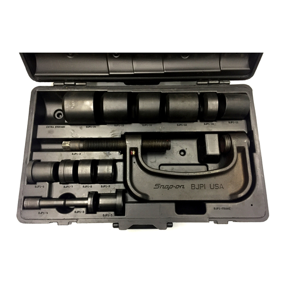
BJP1-BALL JOINT PRESS MASTER SET
Item
Part
No.
No.
1
BJP1-1A
2
BJP1-2
3
BJP1-3A
4
BJP1-4A
5
BJP1-5A
6
BJP1-6A
7
BJP1-7A
8
BJP1-8A
9
BJP1-9A
10
BJP1-10A
11
BJP1-11A
12
BJP1-12A
13
BJP1-13B
14
BJP1-14A
15
BJP1-16A
16
BJP1F
17
BJP1-17
18
ME9A34
19
ME7A207
20
ME7A208A
21
ME7A209A
22
PAKPB061
(Some component assembly required. See component assembly sections.)
Visit the Snap-on web site, www.snapon.com, for vehicle application
ZBJP1B rev B 06/11/2014
Description
SLEEVE ADAPTER
PRESSURE SCREW
LARGE FACED (BALL JOINT)
PRESSURE PAD
SMALL FACED (UNIVERSAL
JOINT) PRESSURE PAD
ADAPTER
ADAPTER/EXTENSION
ADAPTER
ADAPTER
ADAPTER: ANGLE
ADAPTER: ANGLE
ADAPTER
ADAPTER
ADAPTER
ADAPTER
ADAPTER
PRESS FRAME
GREASE FITTING
STEEL BALL
RETAINING RING
LARGE SNAP RING
(11 RINGS REQ'D.)
SMALL SNAP RING
CARRYING/STORAGE CASE
information and complete listing of available adapters.
BJP1-BALL JOINT
PRESS MASTER SET
16
19
20
18
21
17
22
1
Advertisement
Table of Contents

Related Manuals for Snap-On BJP1


Summary of Contents for Snap-On BJP1
- Page 1 LARGE SNAP RING (11 RINGS REQ’D.) ME7A209A SMALL SNAP RING PAKPB061 CARRYING/STORAGE CASE (Some component assembly required. See component assembly sections.) Visit the Snap-on web site, www.snapon.com, for vehicle application information and complete listing of available adapters. ZBJP1B rev B 06/11/2014...
- Page 2 SAFETY INFORMATION IMPORTANT SAFETY INSTRUCTIONS This manual contains important safety and operating instructions for the Snap-on® Ball Joint Press Master set. Refer to the information in this manual as required for safe operation. READ ALL INSTRUCTIONS Read all the instructions in this manual. Read, understand and follow all safety messages and instructions in this manual, and on all ball joint press part components.
- Page 3 Ball Joint Press Component Assembly Insert steel ball (ME9A34) into opening of pressure screw (BJP1-2) as shown in FIG. Secure steel ball inside screw by inserting small snap ring (ME7A209A) into internal snap ring groove of screw as follows: 1. Place snap ring partially into groove while compressing ring so that the ends overlap as shown in FIG.
- Page 4 BJP1 - Operating Information The BJP1 ball joint master set is designed to be used without removing the control arm from the vehicle on most cars and trucks that have press-fit type ball joints.
- Page 5 3. Thread pressure screw (BJP1-2) into end of frame. Insert ball joint pressure pad (BJP1-3A) into pressure screw. (Force pressure pad completely down into pressure screw.) 4. Snap the selected adapters onto adapter sleeve (BJP1-1A) and ball joint pressure pad as shown in FIG. 4.
- Page 6 4. Snap selected adapters into place in the same manner as in the ball joint removal procedure. Use adapter BJP1-6A between pressure pad (BJP1-3A) and adapter if additional length is needed, as shown in FIG. 5.
- Page 7 2. Securely support the drive shaft yoke assembly. Remove all external and/or internal locking rings. 3. If necessary, select one or a combination of adapters (BJP1-1A, BJP1-7A, BJP1-8A) to assist in U- joint replacement. 4. Position press assembly around drive shaft yoke and align pressure pad with face of needle bearing caps, as shown in FIG.
- Page 8 (Refer to the safety information section for required safety instructions.) 1. Securely support the drive shaft yoke assembly. 2. If necessary, select one or a combination of adapters (BJP1-1A, BJP1-7A, BJP1-8A) to assist in replacing the new U-joint. 3. Carefully follow the manufacture’s instructions for lubrication of the new U-joint.
- Page 9 BJP1-24A Not BJP1-11A & BJP1-5A & BJP1-22A & BJP1-5A & 1997-2003 BJP1-1A BJP1-24A BJP1-1A BJP1-11A in BJP1 kit BJP1-6A BJP1-6A BJP1-6A BJP1-6A BJP1-22A Not BJP1-11A & BJP1-5A & BJP1-11A & BJP1-5A & Integra 1989-2001 BJP1-1A BJP1-22A...
- Page 10 2006-2011 N/A - BOLT IN BALL JOINT N/A - STRUT 3 Series 1999-2005 N/A - REPLACE CONTROL ARM N/A - STRUT 1984-1991 BJP1-7A BJP1-8A BJP1-5A BJP1-11A N/A - STRUT 2011-2013 N/A - REPLACE CONTROL ARM N/A - REPLACE CONTROL ARM...
- Page 11 N/A - REPLACE CONTROL ARM N/A - STRUT BJP1-22A Not 1993-99 BJP1-7A BJP1-22A BJP1-5A BJP1-11A N/A - STRUT in BJP1 kit 1986-92 BJP1-7A BJP1-8A BJP1-5A BJP1-11A N/A - STRUT 2012-2013 N/A - REPLACE CONTROL ARM N/A - REPLACE CONTROL ARM...
- Page 12 Lucerne 2006-2011 N/A - CONTROL ARM REPLACE N/A - STRUT Park Avenue 1991-2005 N/A - BOLT IN BALL JOINT N/A - STRUT Rainier 2004-2007 BJP1-12A BJP1-11A BJP1-3A BJP1-13B BJP1-7A BJP1-8A BJP1-5A BJP1-11A Reatta 1990-1991 N/A - BOLT IN BALL JOINT...
- Page 13 N/A - BOLT IN BALL JOINT N/A - BOLT IN BALL JOINT BJP1-22A Not 1990-92 BJP1-22A BJP1-8A BJP1-3A BJP1-12A BJP1-8A BJP1-11A BJP1-5A BJP1-12A in BJP1 kit BJP1-13A/ 1971-1986 BJP1-8A BJP1-11A BJP1-6A N/A - BOLT IN BALL JOINT BJP1-13B BJP1-13A/ 1971-1986 BJP1-6A BJP1-14A...
- Page 14 Remove Remove INFORMATION Install ram Install ram receiver receiver receiver receiver 2010-2013 N/A - CONTROL ARM REPLACE N/A - STRUT Camaro BJP1-13A/ 1990-2002 BJP1-11A BJP1-12A BJP1-6A N/A - BOLT IN BALL JOINT BJP1-13B BJP1-13A/ Caprice 1990-96 BJP1-11A BJP1-12A BJP1-6A N/A - BOLT IN BALL JOINT...
- Page 15 Remove Remove INFORMATION Install ram Install ram receiver receiver receiver receiver 2000-2013 N/A - BOLT IN BALL JOINT N/A - STRUT Impala BJP1-13A/ BJP1-11A BJP1-12A BJP1-6A N/A - BOLT IN BALL JOINT 1994-96 BJP1-13B 1971-1986 BJP1-6A BJP1-11A BJP1-3A BJP1-12A BJP1-8A...
- Page 16 MODEL Install Remove Remove Install Remove Remove INFORMATION Install ram Install ram receiver receiver receiver receiver BJP1-13A/ R1500 1989-1990 BJP1-8A BJP1-11A BJP1-6A N/A - BOLT IN BALL JOINT BJP1-13B BJP1-13A/ R2500 1989-1990 BJP1-12A BJP1-6A BJP1-14A N/A - BOLT IN BALL JOINT...
- Page 17 INFORMATION Install ram Install ram receiver receiver receiver receiver 1988 N/A - BOLT IN BALL JOINT OR KINGPIN N/A - BOLT IN BALL JOINT OR KINGPIN V1500 1989-1990 BJP1-6A BJP1-11A BJP1-3A BJP1-12A BJP1-8A BJP1-11A BJP1-5A BJP1-12A V2500 1989-1990 BJP1-6A BJP1-11A...
- Page 18 1995-2000 N/A - CONTROL ARM REPLACE BJP1-3A BJP1-7A BJP1-5A BJP1-8A BJP1-22A Not Caliber 2007-2012 BJP1-7A BJP1-22A BJP1-3A BJP1-11A N/A - STRUT In BJP1 Kit Caravan 1984-2007 BJP-3A BJP1-7A BJP1-5A BJP1-11A N/A - STRUT Challenger 2009-2013 BJP1-11A BJP1-7A BJP1-5A BJP1-13B N/A - CONTROL ARM REPLACE...
- Page 19 BJP1-28A BJP1-28A 2006-2010 BJP1-28A BJP1-28A Not (short side) BJP1-16A BJP1-5A (long side) & BJP1-11A BJP1-5A BJP1-12A (short side) in BJP1 kit & BJP1-6A BJP1-6A BJP1-6A BJP1-11A BJP1-3A BJP1-14A N/A - CONTROL ARM REPLACE BJP1-28A BJP1-28A 2003-2005 BJP1-28A BJP1-28A Not (short side)
- Page 20 BJP1-3A BJP1-7A BJP1-5A BJP1-11A N/A - STRUT Sprinter BJP1-18A Not BJP1-13A/ 2003-2008 BJP1-12A BJP1-6A BJP1-18A N/A - STRUT 2500 in BJP1 kit BJP1-13B Sprinter BJP1-18A Not BJP1-13A/ 2003-2006 BJP1-12A BJP1-6A BJP1-18A N/A - STRUT 3500 in BJP1 kit BJP1-13B Stealth...
- Page 21 BJP1-24A & Victoria 2003-2004 BJP1-11A BJP1-8A BJP1-5A BJP1-12A BJP1-8A BJP1-5A BJP1-12A Arm BJP1-24A BJP1-6A Not in BJP1 kit 1995-2002 BJP1-6A BJP1-11A BJP1-6A BJP1-12A N/A - BOLT IN BALL JOINT BJP1-13A/ 1992-94 BJP1-11A BJP1-12A BJP1-6A N/A - BOLT IN BALL JOINT...
- Page 22 2011-2013 N/A - CONTROL ARM REPLACE N/A - STRUT BJP1-27A Not 2006-2010 BJP1-12A BJP1-16A BJP1-3A BJP1-27A BJP1-7A BJP1-11A BJP1-5A BJP1-12A in BJP1 kit BJP1-27A Not 2002-2005 BJP1-12A BJP1-16A BJP1-3A BJP1-27A BJP1-7A BJP1-8A BJP1-5A BJP1-11A in BJP1 kit Explorer BJP1-27A Not...
- Page 23 1979 N/A - KINGPIN WITH BUSHINGS N/A - KINGPIN WITH BUSHINGS BJP1-25A Not BJP1-6A & 2005-2013 BJP1-13B BJP1-14A BJP1-8A BJP1-25A BJP1-11A BJP1-10A BJP1-7A in BJP1 kit BJP1-12A F450 1999-2004 BJP1-11A BJP1-16A BJP1-5A BJP1-12A BJP1-8A BJP1-12A BJP1-3A BJP1-12A BJP1-25A Not BJP1-6A &...
- Page 24 1983-1997 BJP1-7A BJP1-8A BJP1-5A BJP1-11A BJP1-7A BJP1-11A BJP1-5A BJP1-11A 2008-2013 N/A - CONTROL ARM REPLACE N/A - STRUT BJP1-11A & BJP1-5A & Taurus 1996-2007 BJP1-7A BJP1-11A N/A - STRUT BJP1-6A BJP1-6A 1986-95 N/A - CONTROL ARM REPLACE N/A - STRUT...
- Page 25 BJP1-14A BJP1-3A BJP1-11A BJP1-5A BJP1-12A BJP1-13B BJP1-29A Not BJP1-11A & BJP1-5A & 2008-2012 BJP1-8A BJP1-29A N/A - CONTROL ARM REPLACE in BJP1 kit BJP1-6A BJP1-6A BJP1-24A Not BJP1-11A & BJP1-5A & BJP1-11A & BJP1-5A & Accord 1990-2007 BJP1-1A BJP1-24A BJP1-1A...
- Page 26 BJP1-22A Not BJP1-11A & BJP1-5A & BJP1-11A & BJP1-5A & Del Sol 1993-97 BJP1-1A BJP1-22A BJP1-1A BJP1-11A in BJP1 kit BJP1-6A BJP1-6A BJP1-6A BJP1-6A Element 2003-2011 N/A - BALL JOINT SOLD IN KNUCKLE N/A - STRUT 2009-2013 BJP1-3A BJP1-7A...
- Page 27 Install ram receiver receiver receiver receiver BJP1-22A Not 2006-2010 N/A - BOLT IN BALL JOINT BJP1-5A BJP1-7A BJP1-5A BJP1-22A in BJP1 kit BJP1-22A Not Sonata 1999-2005 N/A - BOLT IN BALL JOINT BJP1-3A BJP1-7A BJP1-5A BJP1-22A in BJP1 kit (cont.) 1995-98...
- Page 28 1996-99 BJP1-7A BJP1-22A BJP1-5A BJP1-11A BJP1-6A BJP1-11A BJP1-5A BJP1-11A in BJP1 kit Pickup 1981-95 2WD & 4WD N/A - BOLT IN BALL JOINT N/A - BOLT IN BALL JOINT Rodeo 1991-2004 2WD & 4WD N/A - BOLT IN BALL JOINT...
- Page 29 BJP1-22A Not Amanti 2004-2006 N/A - BOLT IN BALL JOINT BJP1-3A BJP1-7A BJP1-5A BJP1-22A in BJP1 kit Borrego 2009 N/A - BOLT IN BALL JOINT N/A - CONTROL ARM REPLACE Forte 2010-2013 N/A - BOLT IN BALL JOINT N/A - STRUT...
- Page 30 N/A - CONTROL ARM REPLACE N/A - CONTROL ARM REPLACE BJP1-27A Not Aviator 2003-2005 BJP1-12A BJP1-16A BJP1-3A BJP1-27A BJP1-7A BJP1-8A BJP1-5A BJP1-11A in BJP1 kit Blackwood 2002 BJP1-12A BJP1-8A BJP1-3A BJP1-14A N/A - CONTROL ARM REPLACE BJP1-11A & BJP1-5A & 1995-2002 BJP1-7A BJP1-11A...
- Page 31 N/A - CONTROL ARM REPLACE Coil Spring BJP1-22A Not BJP1-12A BJP1-8A BJP1-3A BJP1-14A BJP1-7A BJP1-22A BJP1-5A BJP1-11A B Series 1998-2002 in BJP1 kit Trucks Torsion Bar BJP1-12A BJP1-8A BJP1-3A BJP1-14A N/A - CONTROL ARM REPLACE 1994-1997 BJP1-7A BJP1-8A BJP1-5A BJP1-11A...
- Page 32 N/A - SOLD IN KNUCKLE N/A - CONTROL ARM REPLACE BJP1-18A Not BJP1-13A/ Sprinter 2010-2012 BJP1-12A BJP1-6A BJP1-18A N/A - STRUT in BJP1 kit BJP1-13B Capri 1991-94 N/A - BOLT IN BALL JOINT N/A - STRUT BJP1-13A/ Colony Park 1990-91 BJP1-11A...
- Page 33 BJP1-7A BJP1-8A BJP1-5A BJP1-11A N/A - STRUT BJP1-22A Not 2000-2005 BJP1-8A BJP1-22A BJP1-6A BJP1-11A N/A - STRUT Eclipse in BJP1 kit 1995-1999 N/A - CONTROL ARM REPLACE BJP1-3A BJP1-7A BJP1-5A BJP1-8A 1990-94 BJP1-7A BJP1-8A BJP1-5A BJP1-11A N/A - STRUT Endeavor...
- Page 34 BJP1-11A N/A - STRUT Maxima BJP1-22A Not 1995-99 BJP1-7A BJP1-22A BJP1-5A BJP1-11A N/A - STRUT in BJP1 kit 1985-94 N/A - BOLT IN BALL JOINT N/A - STRUT 2009-2013 N/A - CONTROL ARM REPLACE N/A - STRUT Murano 2003-2007 BJP1-7A...
- Page 35 MODEL Install Remove Remove Install Remove Remove INFORMATION Install ram Install ram receiver receiver receiver receiver Acclaim 1989-95 BJP1-3A BJP1-7A BJP1-5A BJP1-11A N/A - STRUT Breeze 1996-2000 N/A - CONTROL ARM REPLACE BJP1-3A BJP1-7A BJP1-5A BJP1-11 Colt 1989-94 BJP1-7A BJP1-8A...
- Page 36 BJP1-12A BJP1-28A BJP1-28A BJP1-28A BJP1-28A Not (short side) BJP1-16A BJP1-5A (long side) & BJP1-11A BJP1-5A BJP1-12A (short side) 2500 2011-13 in BJP1 kit & BJP1-6A BJP1-6A BJP1-12A BJP1-16A BJP1-3A BJP1-14A BJP1-7A BJP1-11A BJP1-6A BJP1-12A BJP1-28A BJP1-28A BJP1-28A BJP1-28A Not (short side)
- Page 37 N/A - BOLT IN BALL JOINT N/A – STRUT BJP1-22A Not Echo 2000-2005 BJP1-3A BJP1-7A BJP1-5A BJP1-22A N/A – STRUT in BJP1 kit 2010-2013 N/A - CONTROL ARM REPLACE N/A - CONTROL ARM REPLACE FJ Cruiser BJP1-13A/ 2007-2009 BJP1-12A BJP1-11A BJP1-3A...
- Page 38 N/A – STRUT BJP1-22A Not BJP1-13A/ 2005-2013 BJP1-12A BJP1-11A BJP1-3A BJP1-14A BJP1-7A BJP1-22A BJP1-5A in BJP1 kit BJP1-13B Tacoma N/A - BOLT IN BALL JOINT N/A - BOLT IN BALL JOINT 1995-2004 N/A - BOLT IN BALL JOINT BJP1-7A BJP1-8A BJP1-5A BJP1-11A...
- Page 39 Install ram receiver receiver receiver receiver 1997-98 N/A - BOLT IN BALL JOINT N/A - STRUT 2000-2004 BJP1-3A BJP1-11A BJP1-5A BJP1-11A N/A - STRUT 2005-2011 N/A - BOLT IN BALL JOINT N/A - STRUT 1998-2010 N/A - BOLT IN BALL JOINT...
Need help?
Do you have a question about the BJP1 and is the answer not in the manual?
Questions and answers