Table of Contents
Advertisement
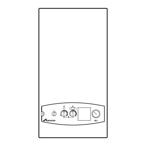
24Si II / 28Si II
WALL MOUNTED COMBINATION BOILERS FOR CENTRAL HEATING
AND MAINS FED DOMESTIC HOT WATER
INSTALLATION AND
SERVICING INSTRUCTIONS
This appliance is for use with Natural Gas or LPG (Cat II 2H3P TYPE C12 & C32)
24Si II GC NUMBER 47 311 65 (N.G.)
28Si II GC NUMBER 47 311 67 (N.G.)
Minimum
Maximum
IMPORTANT: THESE INSTRUCTIONS APPLY IN THE GB/IE ONLY
AND MUST BE LEFT WITH THE USER OR AT THE GAS METER
It is IMPORTANT to read the instructions before starting work - they have been
written to make the installation easier and prevent hold-ups.
GC NUMBER 47 311 66 (L.P.G.)
GC NUMBER 47 311 68 (L.P.G.)
GB/IE
APPLIANCE OUTPUTS
Domestic
Central Heating
Hot Water
24Si II
28Si II
24Si II
6.9 kW 8.1 kW
6.9 kW 8.1 kW
24 kW 28 kW
24 kW 28 kW
28Si II
Advertisement
Table of Contents

Related Manuals for Worcester 24SiII


Summary of Contents for Worcester 24SiII
-
Page 1: Servicing Instructions
24Si II / 28Si II WALL MOUNTED COMBINATION BOILERS FOR CENTRAL HEATING AND MAINS FED DOMESTIC HOT WATER INSTALLATION AND SERVICING INSTRUCTIONS This appliance is for use with Natural Gas or LPG (Cat II 2H3P TYPE C12 & C32) 24Si II GC NUMBER 47 311 65 (N.G.) GC NUMBER 47 311 66 (L.P.G.) 28Si II GC NUMBER 47 311 67 (N.G.) GC NUMBER 47 311 68 (L.P.G.) -
Page 2: Table Of Contents
BS6798 and BS5440 Part 2. However, because of the Contact Worcester Heat Systems Technical Department, Telephone: 08705 266241, for advice on specific installations. low casing losses, there is no need for cooling ventilation openings in... - Page 3 the compartment provided the increased clearances are used. 2.10 Safety See Fig. 5. The appliance must not be operated with the inner casing The spaces specified for servicing must be maintained.(See Table 8). cover removed or without being full of water and pressurised. There is space for the service pipes to pass at the back of the appliance.
-
Page 4: Technical Data
3. Technical Data Table 1. 24Si II Table 1. 28Si II NOMINAL BOILER RATINGS (10 Minutes After Lighting) NOMINAL BOILER RATINGS (10 Minutes After Lighting) BOILER ADJUSTED FOR G20 (Natural Gas) BOILER ADJUSTED FOR G20 (Natural Gas) BURNER BURNER OUTPUT INPUT (Net) GAS RATE OUTPUT... - Page 5 Table 5 PERFORMANCE SPECIFICATIONS 24Si II 28Si II PRIMARY WATER CAPACITY litres IP RATING (WHOLE OF BOILER) IP 20 MAXIMUM MAINS INLET PRESSURE MINIMUM MAINS INLET PRESSURE (WORKING) FOR MAXIMUM FLOW MINIMUM MAINS INLET PRESSURE (WORKING) FOR OPERATION 0.25 DOMESTIC HOT WATER TEMPERATURE RANGE °C 40 - 60 MAXIMUM CENTRAL HEATING FLOW TEMPERATURE...
- Page 6 Fig. 6. Side flue opening Fig. 3. Appliance casing dimensions and required clearances for installation/servicing 24Si II = 400 28Si II = 440 All dimensions in mm All dimensions in mm Fig. 4. Appliance casing dimensions and Fig. 7. Pipework connections required clearances (side view).
-
Page 7: Siting The Appliance
4. Siting The Appliance 5. Flue terminal positions The appliance may be installed in any room but refer to the The flue system must be installed following the requirements of requirements of the current IEE Regulations and, in Scotland, the BS5440: 1. -
Page 8: Air Supply
6. Air Supply 7. Sealed System 6.1 A separate vent for combustion air is not required. Refer to The system must comply with requirements of BS6798 and BS5440:2. BS5449 and must not be operated without being full of water If the appliance is in a cupboard or compartment then, because and correctly pressurised. -
Page 9: Domestic Hot Water
Fig 10 - System Fill Fig 11 - System make up Heating Mains water return supply 300mm Above Non return Non return the highest point valve valve Hose union of the system 1.Central Heating Return Stop 2.Auto Air vent cock 3.Non-return Valve Test cock Temporary hose... - Page 10 Fig. 12. Wiring diagram. Pressure Switch small tab=L high speed (red) medium tab = L low speed (white) large tab=N (black) Overheat cut-off device black CH sensor (front of heat exchanger) Flame sense electrode Spark electrode Gas valve Regulator valve Flow turbine DHW sensor...
- Page 11 Fig. 13. Functional flow diagram. Inputs Outputs DHW control knob CH Control knob Electronics/ microprocessor (Safety Low Voltage) Gas valve mode switch Reset button Convert AC to low Electronics voltage electronics Electronics Pump Electronics...
-
Page 12: Installing The Appliance
Fig. 14. Access to internal fuses and Fig. 15 . Mains electricity connections. electrical connections. Ns Ls 230V MAINS 230V 1. Connection cover fixing screws 2. Connection cover 3. Control panel 4. Connections 11.6 Gas and Water Pipes 11. Installing The Appliance Remove the gas cock and fix the appropriate fitting to connect the inlet pipe and refit. - Page 13 Fig. 17 . Manifold assembly Fig. 19 . Wall mounting frame Wall Frame Wall Fibre Frame Washer 1. Wall mounting frame 2. Hanging bracket 3. Appliance Flow Flow 4. Support hook Cold Inlet Return Lift the appliance to the wall, engage in the top support and lower onto the manifold assembly.
- Page 14 Fig. 21. Inner case and facia fixing Fig. 22. Flue spigot and restrictor 1. Flue spigot fixing screws 2. Flue spigot 3. Restrictor ring 4. Flue spigot fixing holes Fig.23. Standard flue assembly Terminal assembly Flue Fixing screw turret assembly Telescopic adjustment Appliance casing...
- Page 15 (4 extension) 11.11 Fitting of the Flue Assembly without access to the Terminal. The rubber gasket kit is available from Worcester Heat Systems. NOTE: A larger diameter opening in the wall is required. Refer to (* Maximum length 2500mm for LPG boilers)
- Page 16 Prepare the flue assembly as described in Section 11.8. Fig. 27 . Flue Turret Fixing Fit the rubber sealing gasket centrally onto the terminal assembly and tighten the clamp. Refer to Fig. 28. Apply the plastic tape to the air duct to be in contact with the external brickwork.
- Page 17 If Z is greater than 725mm then two extension duct assemblies will Connect the mains supply lead to the appliance and secure in be required, the first assembly being cut to length as plain tubes. the cable clamp. Make sure that the lead is isolated before connection.
- Page 18 Fig 36 - Mains Voltage External Controls Fig. 34. Programmer cover Connections spare spare Ns Ls Ns Ls L Ns Ls Ns Ls L Remove Link Remove Link Motor 230 V Room Thermostat Connections 230 V Programmer Connections 230 V room thermostat and Programmer Connections 1.
-
Page 19: Commissioning The Appliance
Fig. 39. Gas valve. Fill the system through an external WRAS approved filling loop Allen key or Worcester Filling Link and Key optional extra, Part N : 7 716 192 281. Refer to Section 7, Sealed System. Vent each radiator in turn. The automatic air vent, cap removed, will vent the appliance. - Page 20 Worcester Heat Systems Service Department should be contacted. automatically balance with the system requirements. If the appliance does not light then check that it is not in the ‘lock-out’...
-
Page 21: Handover
13. Handover Fig. 42. Inner case and facia fixing Fig. 41. Facia controls 1. Mains On/Off control 5. Optional programmer 2. CH temperature control 6. Lockout indicator lamp and 3. DHW temperature control reset button 4. System pressure gauge 7. Burner indicator lamp Hand over the User Booklet and the completed Benchmark Logbook. - Page 22 Fig. 44. Inner case components 1. Flue hood 9. Inner case 2. Primary sensor 10. Fan assembly 3. Heat exchanger 11. Inner case cover fixing (top) 4. Combustion chamber assembly 12. Air pressure switch 5. Spark electrode assembly 13. Combustion sensing point 6.
- Page 23 Inner Case Cover Unscrew the four screws and remove. Refer to Fig 42. 14.4 Component Cleaning Combustion Chamber Unscrew the two screws at the top and Only use a non-metallic brush to clean components. Do not use a the two wing nut extended screws at the sides, pull metal probe to clean the injectors.
-
Page 24: Replacement Of Parts
15.1 Gas Valve 15. Replacement Of Parts Unscrew the union connections above and below the gas valve and remove the assembly. Disconnect/unplug the electrical IMPORTANT: Turn off the gas supply and electrically isolate connections from the valve. the appliance before replacing any components. Use new gaskets when replacing the valve. - Page 25 15.2 Spark Electrode Fig. 50. Flame sense electrode Remove the inner casing cover and the combustion chamber. Carefully pull off the lead from the electrode. Unscrew the screw and remove the assembly. Refer to Fig 49. Ensure that the electrode is at the correct height above the burner blade.
- Page 26 15.5 Combustion Chamber Insulation, Front &Sides Fig. 54. Relief valve boiler drain connection Remove inner casing door and combustion chamber. Remove damaged insulation, replacement is the reverse of removal. See Fig 52. Combustion Chamber Insulation, Rear Remove heat exchanger as described in 15.21. Remove side panels first.
- Page 27 15.9 Inlet Water Filter 15.12 Clock/Programmer Remove the flow turbine as described in 15.8 preceding. Remove the facia by gently pulling it away from the boiler to Taking care, remove flow restrictor assembly from the flow turbine release the clips. inlet.
- Page 28 15.15 Primary [ch] Sensor Fig. 59. Primary (CH) sensor. Remove the clip-on facia cover, cabinet and inner casing cover. Carefully pull-off the connections. Release the clip and lift out the sensor. Refer to Fig 59 and 62. Do not omit the heat transfer paste when fitting the replacement sensor.
- Page 29 Fig. 62. Primary heat exchanger 1. Heat exchanger 2. CH flow/return pipes 3. DHW inlet/outlet pipes 4. Seal 5. Overheat thermostat 6. Primary sensor 15.22 Air pressure Switch The air pressure switch is held in position by a fixing bracket. In order to remove the switch: Gently move outwards the securing clips holding the switch to Fig.
-
Page 30: Short Parts List
16. Short Parts List G.C. No. Part Part No. E88-141 Burner 24Si II NG RSF 8 716 101 900 0 E88-142 Burner 24Si II LPG RSF 8 716 102 396 0 E88-143 Burner 28Si II NG RSF 8 716 105 008 0 E88-144 Burner 28Si II LPG RSF 8 716 105 009 0... - Page 31 1 - 4 16 -17 14 -15 23 - 24 30 - 31 28 - 29...
-
Page 32: Operational Flow Diagram
17. Operational Flow Diagrams CENTRAL HEATING FUNCTION Room thermostat and/or mains programmer (or link) On MAIN SWITCH facia programmer (if fitted) On CH control knob On Fifteen second Modulate gas Pump on. minimum to maintain Fan ON/ burner CENTRAL flow ignition pressure then DEMAND... - Page 33 OVERRUN FUNCTION Pump on if primary temp Pump overrun above 80° END DHW function active until temp DEMAND for 3 minutes below 75°C Fan low speed if primary temp Fan low speed 35 seconds above 80°C until below 75°C. Pump runs END CH DEMAND 3 minutes...
-
Page 34: Fault Finding
18. Fault Finding Note: This fault-finding information is for guidance only. Worcester Heat Systems cannot be held responsible for costs incurred by persons not deemed to be competent. By flashing at various rates, the oval shaped facia light will indicate specific fault conditions. If this is used with other observations during a fault, then every normal fault can be identified. - Page 35 NOTE: It is normal for there to be no facia lights if the boiler is in normal overtempera- ture condition. Continue this test if this fault occurs when the appliance is cold. Is there a 230V AC live supply across Check electrical Terminal ST2 pins L supply to boiler.
- Page 36 Disconnect the 3 way in-line connector to the turbine. Is there continuity in Replace main Is there 5VDC between the main harness? harness. the two outer pins (main harness side)? Take care not to damage the pins. Replace control board. Re-connect the 3-way connector and open a tap to run the turbine.
- Page 37 Is the gas supply Rectify gas supply connected and at the problem. correct pressure? Remove front panel. Remove inner cover. Reset and restart the Reset and restart the Are the electrodes and Repair or replace boiler. Can a flame be boiler.
- Page 38 Turn off boiler. Remove inner casing cover and inspect the primary sensor (on heat Re-fix sensor to pipe. exchanger in front of overheat thermostat). Is it correctly fixed to pipe? Remove combustion chamber cover. Replace flame sensor Is the sense electrode or wiring.
- Page 39 Is the Code plug fitted Fit/push fully home fully home? Is the multiway connector at board position ST16 pushed Push fully home fully home on to the board? Check the DHW sensor. Is it correctly Re-fix sensor onto pipe fitted onto the pipe with heat conductive paste between the pipe and sensor?
- Page 40 Replace multiway connector to position ST16 (but not fan connector at ST1) and Replace control board. reset/restart the In the unlikely event boiler. of this not solving the Is there mains 230V problem replace code across the right (L) plug. and left (N) tracks at board position ST1? NOTE: Take care not to...
- Page 41 Is the boiler in a very Replace control board. cold environment (less Note: A damp board than 5°C)? could cause this fault. Boiler is running in “Autofrost stat” mode. See Section 17. Hot water Hot water sensor Could be temperature always could be off or poorly domestic hot too hot during a...
-
Page 42: Conversion Instructions
13. Turn off the boiler and when cool peel off the arrow from the data plate on the combustion box front panel and re-stick ONLY COMPONENTS SUPPLIED BY WORCESTER HEAT against the gas type for which the boiler has been converted SYSTEMS SHOULD BE USED. - Page 44 This manual is to be used in conjunction with the variant part number of the bar code below: Bosch Group Worcester Heat Systems Limited (Bosch Group), Cotswold Way, Warndon, Worcester WR4 9SW. Telephone: (01905) 754624. Fax: (01905) 754619. Technical Helpline (08705) 266241. www.worcester-bosch.co.uk This booklet is accurate at the date of printing but will be superseded and should be disregarded if specifications and/or appearances are changed in the interests of continued improvement.
-
Page 45: Flue System
VERTICAL BALANCED FLUE SYSTEM INSTALLATION INSTRUCTIONS ROOM SEALED NON-CONDENSING COMBINATION/SYSTEM BOILERS AND WATER HEATERS 47 311 37/38 9/14 CBi 41 311 50/51 47 311 54 14/19 CBi 41 311 52/53 25Si 47 311 49/50 19/24 CBi 41 311 54/55 28Si 47 311 51/52 WR325 52 311 02... - Page 46 1. Flue Terminal Position Fig. 1. Terminal Position Pitched Roof The Flue System must be installed in accordance with BS 5440: Part 1 2000 where applicable. When installed the minimum clearance between the terminal and any adjoining vertical walls or obstructions must be at least 500mm.
- Page 47 35CDiII NONE 24CDi NONE 28CDi NONE With terminal section only With longer flues no 24SiII use 78 mm restrictor restrictor must be fitted With terminal section only With longer flues no 28SiII Minimum 76mm use 82 mm restrictor restrictor must be fitted...
- Page 48 Fig. 5. Adaptor Ensure the ducts are correctly located into the socketed joints. 3. Preparation and General Notes Fixing screws 3.1. FLUE HEIGHT AND OFFSETS. Determine the height of the flue system and if offsets are needed for the system to miss ceiling/roof joists and any other obstruction.
- Page 49 3.8. POSITIONING THE FLUE SYSTEM It may be necessary to deviate from the following method of installation because of site conditions. However, joints must be sealed and fixed as described. Align the centre of the flue spigot with the ceiling and mark the centre position.
- Page 50 4. Measurement of Ducts 4.1 AIR AND FLUE DUCT LENGTHS - NO OFFSET For a flat roof measure the distance from the appliance top panel to the outside edge of the hole diameter marked on the inside surface of the roof. This is dimension 'E ' Refer to Fig.
- Page 51 4.2 AIR AND FLUE DUCT LENGTHS - OFFSET WITH VERTICAL 2nd Vertical Section: Measure the distance from centre-line of the horizontal offset ADAPTER (90° or, where applicable, 45° bends) to the outside edge of the hole diameter marked on the 1st Vertical Section: inside surface of the roof.
- Page 52 4.3 AIR AND FLUE DUCT LENGTHS - OFFSET WITHOUT Vertical Section: VERTICAL ADAPTER (90° or, where applicable, 45° bends) Measure the distance from the centre-line of the horizontal Measure the distance from the centre of the flue spigot on offset to the outside edge of the hole diameter marked on the top of the appliance to the centre line of the vertical sections.
- Page 53 Fig. 12. Vertical flue system (offset with 45° flue bends) Air inlet flange Weather sealing collar (Secure with screw provided and seal with silicone sealant) 300mm Roof flashing (not supplied) minimum Flat roof Height of terminal assembly 1100mm G = 1100mm - F L = K - G Flue terminal assembly (106mm diameter)
- Page 54 5.5 ASSEMBLY OF DUCTS 5.8 FIX THE FLUE SYSTEM ASSEMBLY TO THE APPLIANCE 5.5.1 AIR DUCTS From inside the building, assemble the flue system starting Check the assembled length of the ducts. Drill two holes at the appliance. refer to Fig. 6, 8, 9 and 10. through the pilot holes in the expanded end of the air duct Align the flue assembly or the first section of flue with the and fix the ducts together with the screws provided.
- Page 55 Important: Do not forget to fix the fire stop spacer as the assembly of the system proceeds. 5.9 FIX THE FLUE TERMINAL ASSEMBLY Fit the roof flashing loosely to the roof. From outside, pass the terminal assembly through the roof flashing.
- Page 56 Bosch Group Worcester Heat Systems Limited, Cotswold Way, Warndon, Worcester WR4 9SW. Telephone: (01905) 754624. Fax: (01905) 754619. Technical Helpline 08705 266241. www.worcester-bosch.co.uk This booklet is accurate at the date of printing but will be superseded and should be disregarded if specifications and/or appearances are changed in the interests of continued improvement.
- Page 57 Replace white case. Fig. 1. Programmer connection 1 Dial 2 Time Pointer 3 Manual Selector 4 Tappets Worcester Heat Systems Limited, Cotswold Way, Warndon, Worcester WR4 9SW. 8 716 145 228a 01/00 Telephone: (01905) 754624. Fax: (01905) 754619. Technical Helpline (0990) 266241.
- Page 58 DIGITAL SINGLE-CHANNEL PROGRAMMER FITTING AND OPERATING INSTRUCTIONS General information is given in the users instruction leaflet despatched with the appliance and/or on the lighting instruction plate fitted to the appliance. TWICE ONCE CONFORMS TO THE ESSENTIAL REQUIREMENTS OF THE FOLLOWING DIRECTIVES: 89/336/EEC - Electromagnetic compatibility 73/23/EEC - Low voltage Directive THESE INSTRUCTIONS APPLY IN THE UK ONLY...
- Page 59 Gas Safety (Installation and Use) Regulations 1984 : All gas appliances must be installed by a competent person, in accordance with the above regulations. Failure to install the appliance correctly could lead to prosecution. The manufacturers notes must not be taken, in any way, as overriding statutory obligations.
- Page 60 Programmer connection Fig. 1. TO REPLACE THE PROGRAMMER Follow the preceding instructions.
- Page 61 TWICE ONCE...
- Page 62 PROGRAMMER OPERATING INSTRUCTIONS The programmer controls the operation of the central heating circuit. The domestic hot water is permanently available upon demand and will take priority over the supply of heat to the system during the demand. Pressing the SET button repeatedly progresses you through the settings. To reset at any point the YES button must be pressed, followed by the + and –...
- Page 63 TO TEST THE PROGRAMME The test feature enables you to quickly run through the programme which has been set and check that all is correct with both the programme and the system. Pressing the YES button in response to TEST? selects the test mode. Pressing and holding down the YES button starts the clock fast running until it reaches the first switching time when the output changes and the display halts to show the time of switching and the output state.
- Page 64 Temperature Control: The Central Heating water temperature is controlled by the centre knob on the facia. The Domestic Hot Water Temperature is controlled by the right hand knob on the facia. Standard Programme: To return to the standard programme press the SELECT and + buttons together. TO LIGHT AND STOP THE APPLIANCE Refer to the User operating instruction leaflet or the lighting instruction plate on the appliance.
- Page 65 Worcester Heat Systems Ltd. (Bosch Group), Cotswold Way, Warndon, Worcester WR4 9SW. Telephone: 01905 754624. Fax: 01905 754619. Technical Helpline 08705 266241 www.worcester-bosch.co.uk This booklet is accurate at the date of printing but will be superseded and should be disregarded if specifications and/or appearances are changed in the interests of continued improvement.
Need help?
Do you have a question about the 24SiII and is the answer not in the manual?
Questions and answers