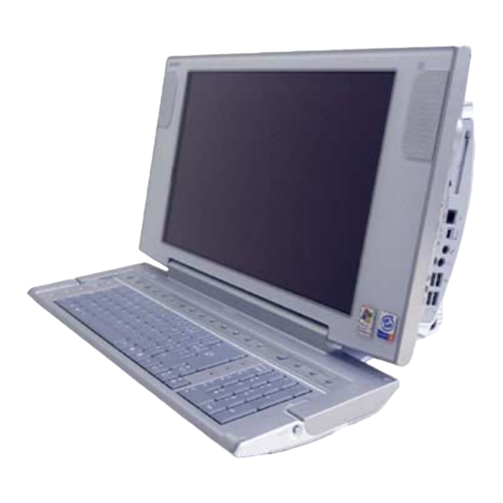
Sony vaio PCV-W500GN1 Service Manual
17 inch
Hide thumbs
Also See for vaio PCV-W500GN1:
- Specifications (129 pages) ,
- Supplementary manual (9 pages) ,
- Service manual (38 pages)
Table of Contents
Advertisement
Quick Links
SERVICE MANUAL
PCV-W Series
American Area
US Model
Canadian Model
Ver. 6-2005E
Revision History
Line up: PCV-W500GN1
PCV-W510G
PCV-W600G
PCV-W700G
• Design and specifications are subject to
change without notice.
2005E0500-1
©2005 Sony Corporation
Published by Sony EMCS NAGANO TEC
9-874-380-15
TOP
FOR SAFETY
DISASSEMBLY
FRAMEHARNESS
( 17inch )
PCV-W700G
PARTS LIST
EXPLODED VIEW
PERSONAL COMPUTER
Advertisement
Table of Contents

Related Manuals for Sony vaio PCV-W500GN1


Summary of Contents for Sony vaio PCV-W500GN1
- Page 1 American Area US Model Canadian Model Ver. 6-2005E PCV-W700G Revision History Line up: PCV-W500GN1 PCV-W510G PCV-W600G PCV-W700G • Design and specifications are subject to PERSONAL COMPUTER change without notice. 2005E0500-1 ©2005 Sony Corporation Published by Sony EMCS NAGANO TEC 9-874-380-15...
- Page 2 1. Obey precautionary markings and 4. Inspect after completing service Sony, VAIO and CLIE are trademarks or regis- and the service instructions. instructions tered trademarks of Sony. Microsoft, Windows,...
- Page 3 FOR SAFETY DISASSEMBLY PARTS LIST FRAMEHARNESS EXPLODED VIEW DISASSEMBLY 3 REAR COVER 4 ANL-42 BOARD ENX-25 BOARD, 10 MOTHER BOARD RISER BOARD (CI-R) 7 MAIN UNIT 1 11 DC FAN (WITH HEAT 1 TOP (COVER) ASSY 5 HDD SINK) 8 MAIN UNIT 2 2 MEMORY MODULE 6 IO (PANEL) ASSY, 13 SWITCHING POWER...
- Page 4 FOR SAFETY DISASSEMBLY PARTS LIST FRAMEHARNESS EXPLODED VIEW DISASSEMBLY CONTINUED FROM PREVIOUS PAGE 14 FRONT UNIT 15 REAR COVER (LCD) 16 KEYBOARD UNIT ASSY 19 LEX-48 BOARD LCD UNIT CNX-217 BOARD, INVERTER UNIT, RAY-CATCHER UNIT OPTICAL DRIVE, SLIMIDE BOARD 1 24 ANL-41 BOARD 18 SPEAKER UNIT OPTICAL DRIVE, SLIMIDE BOARD 2...
-
Page 5: Top (Cover) Assy
FOR SAFETY DISASSEMBLY PARTS LIST FRAMEHARNESS EXPLODED VIEW DISASSEMBLY TOP (COVER) ASSY Removal procedure Detents 1 While pressing the release Detents Top (cover) assy button, slide the Top (cover) Release button assy in the direction of the arrow and disengage the Detents To Flowchart nine detents. - Page 6 FOR SAFETY DISASSEMBLY PARTS LIST FRAMEHARNESS EXPLODED VIEW DISASSEMBLY MEMORY Removal procedure 1 Remove the Memory module screw. +B (3 X 6) 7-682-547-09 Black Memory protection To Flowchart bracket 2 Remove the Memory protection bracket. 3 Open the two clips. 4 Pull out the Memory module from the board in the vertical direction.
-
Page 7: Rear Cover
FOR SAFETY DISASSEMBLY PARTS LIST FRAMEHARNESS EXPLODED VIEW DISASSEMBLY REAR COVER Removal procedure 1 Remove the two screws. +B (3 X 6) 7-682-547-09 Black To Flowchart 2 Remove the two screw-covers. 3 Remove the four screws. +B (3 X 6) 7-682-547-04 Silver 4 Disengage the eleven... -
Page 8: Anl-42 Board
FOR SAFETY DISASSEMBLY PARTS LIST FRAMEHARNESS EXPLODED VIEW DISASSEMBLY ANL-42 BOARD Removal procedure When installing, connect 1 Remove the the connectors having screw. +B (3 X 6) the same color together. 7-682-547-09 Black ANL-42 board To Flowchart 2 Disengage the two detents, and remove the AMP bracket and the White... - Page 9 FOR SAFETY DISASSEMBLY PARTS LIST FRAMEHARNESS EXPLODED VIEW DISASSEMBLY Removal procedure 1 Remove the four screws. +B (3 X 6) 7-682-547-09 Black To Flowchart 2 Remove the bracket assy and HDD in the direction of the arrow. 3 Peel off the Nickel cloth (*1) tape 4 Remove the two...
-
Page 10: Io (Panel) Assy, Hinge (Cover)
FOR SAFETY DISASSEMBLY PARTS LIST FRAMEHARNESS EXPLODED VIEW DISASSEMBLY IO (PANEL) ASSY, HINGE (COVER) Removal procedure 1 Remove the five screws, and remove the Hinge (cover) Detents Main shassis (stay). To Flowchart +B (3 X 6) 7-682-547-09 Black 2 Disengage the four detents, and remove the IO (panel) assy. -
Page 11: Main Unit
FOR SAFETY DISASSEMBLY PARTS LIST FRAMEHARNESS EXPLODED VIEW DISASSEMBLY MAIN UNIT-1 Removal procedure 1 Disconnect the harness Cable clamp from the cable clamp. UL tape 2 Peel off the UL tape. To Flowchart 3 Remove the four screws. +B (3 X 6) 7-682-547-09 Black To next page... - Page 12 FOR SAFETY DISASSEMBLY PARTS LIST FRAMEHARNESS EXPLODED VIEW DISASSEMBLY MAIN UNIT-2 Removal procedure 1 Peel off the Nickel cloth tape which connects MPEG bracket and MAIN chassis. (W600G/W700G) To Flowchart 2 Disconnect the harness by staighting up coating clip Coating clip slightly.
- Page 13 FOR SAFETY DISASSEMBLY PARTS LIST FRAMEHARNESS EXPLODED VIEW DISASSEMBLY ENX-20/26 BOARD, RISER BOARD Removal procedure Coaching clip 1 Remove the two connectors. Riser 2 Peel off the copper leaf tape. board (W500GN1/W510G) 3 Remove the ENX-20/26 board To Flowchart three screws. +B (3 X 6) 7-682-547-09 Black...
-
Page 14: Mother Board
FOR SAFETY DISASSEMBLY PARTS LIST FRAMEHARNESS EXPLODED VIEW DISASSEMBLY MOTHER BOARD Removal procedure 1 Remove the two screws. +PSW (3 X 5) 7-682-946-01 Gold To Flowchart CNR (askey) modem 2 Lift up the CNR (askey) modem in the direction of the arrow A, and disconnect Mother board the B-to-B connector. -
Page 15: Dc Fan (With Heat Sink)
FOR SAFETY DISASSEMBLY PARTS LIST FRAMEHARNESS EXPLODED VIEW DISASSEMBLY DC FAN (WITH HEAT SINK) Removal procedure Clips 1 Remove the connector. Clip When assembling, make sure that the clips securely hook 2 Press the clips in the on the sockets. direction of the arrow A Sockets to release the lock and... - Page 16 FOR SAFETY DISASSEMBLY PARTS LIST FRAMEHARNESS EXPLODED VIEW DISASSEMBLY Removal procedure 1 Raise the lever in the direction of the arrow A. 2 Pull the CPU straight up and remove it. To Flowchart To replace the CPU or heat sink (in case that CPU is equipped with heat sink), install new CPU or heat sink after thermal dissipation grease is wiped off and apply the grease to the position shown...
-
Page 17: Switching Power
FOR SAFETY DISASSEMBLY PARTS LIST FRAMEHARNESS EXPLODED VIEW DISASSEMBLY SWITCHING POWER Removal procedure Attach the UL tape 1 to 1 Peel off the UL tape. secure the harness as shown in the right picture. 2 Remove the two screws. +K (3 X 8) 7-682-248-04 To Flowchart Silver... -
Page 18: Front Unit
FOR SAFETY DISASSEMBLY PARTS LIST FRAMEHARNESS EXPLODED VIEW DISASSEMBLY FRONT UNIT Removal procedure Herness cover 1 Remove the connector. Front unit bracket assy 2 Remove the four screws, and remove the Hinge (main) and the Front unit together. To Flowchart +PS (4 X 5) Route harnesses as shown below. -
Page 19: Rear Cover (Lcd) Assy
FOR SAFETY DISASSEMBLY PARTS LIST FRAMEHARNESS EXPLODED VIEW DISASSEMBLY REAR COVER (LCD) ASSY Rear panel assy Removal procedure Detents Detent part 1 Disengage the lower two detents and the upper Rear cover (*1) (LCD) assy detent part, and remove the rear panel assy. -
Page 20: Keyboard Unit
FOR SAFETY DISASSEMBLY PARTS LIST FRAMEHARNESS EXPLODED VIEW DISASSEMBLY KEYBOARD UNIT Removal procedure Route the cables as shown in the figure. 1 Peel off the UL tape. Attach the UL tape (1) to secure Keyboard harness 2 Disconnect the connector. the harness as Align the harness along shown in the... -
Page 21: Cnx-217 Board, Inverter Unit, Ray-Catcher Unit
FOR SAFETY DISASSEMBLY PARTS LIST FRAMEHARNESS EXPLODED VIEW DISASSEMBLY CNX-217 BOARD, INVERTER UNIT, RAY-CATCHER UNIT Removal procedure Attach the two UL tapes (8) UL tape to secure the harness and 1 Open wide the Coating clip, and disconnect the harness. the flexible flat cable (LED) as shown in the right picture. -
Page 22: Speaker Unit
FOR SAFETY DISASSEMBLY PARTS LIST FRAMEHARNESS EXPLODED VIEW DISASSEMBLY SPEAKER UNIT Removal procedure 1 Peel off the three UL tapes. 2 Remove the Speaker unit and the Speaker bushing Speaker bushing together, and remove the To Flowchart Speaker bushing. Speaker unit UL tape Attach the three UL tapes (1) to secure the harness and the flexible flat cable (LED) as... - Page 23 FOR SAFETY DISASSEMBLY PARTS LIST FRAMEHARNESS EXPLODED VIEW DISASSEMBLY LEX-48 BOARD Removal procedure Give folding to flexible flat board 1 Remove the LCD unit, LCD chassis assy, three screws. and others. +PS (3 X 6) LEX-48 board 7-682-647-01 Ground plate Aluminum tape Flexible flat cable Gold...
- Page 24 FOR SAFETY DISASSEMBLY PARTS LIST FRAMEHARNESS EXPLODED VIEW DISASSEMBLY LCD UNIT Removal procedure 1 Peel off the nine Nickel cloth tapes (*1) and the two UL tapes. LCD chassis assy 2 Remove the Nickel cloth tape Nickel cloth tape four screws. To Flowchart (W600G/W700G) Nickel cloth tape...
- Page 25 FOR SAFETY DISASSEMBLY PARTS LIST FRAMEHARNESS EXPLODED VIEW DISASSEMBLY OPTICAL DRIVE, SLIMIDE BOARD-1 Removal procedure Optical drive, Slimide board, (*1) and the Drive holder 1 Disconnect the two connectors. 2 Remove the four screws. To Flowchart +PS (3 X 6) 7-682-647-01 Gold 3 Remove the...
- Page 26 FOR SAFETY DISASSEMBLY PARTS LIST FRAMEHARNESS EXPLODED VIEW DISASSEMBLY OPTICAL DRIVE, SLIMIDE BOARD-2 Removal procedure Gasket (6X6) (W700G) 1 Disconnect the Harness. Copper leaf tape (*1) 2 Peel off the Gasket (6X6) UL tape (W600G/W700G) (*2) (W600G) and Copper leaf tape (*3) UL tape To Flowchart...
- Page 27 FOR SAFETY DISASSEMBLY PARTS LIST FRAMEHARNESS EXPLODED VIEW DISASSEMBLY OPTICAL DRIVE, SLIMIDE BOARD-3 Removal procedure W600G/W700G Model (*1) 1 Peel off the Gasket (6X6) and the Nickel cloth tape. 2 Remove the screw, and To Flowchart +P (2 X 2) remove the Detents 7-627-853-07...
-
Page 28: Anl-41 Board
FOR SAFETY DISASSEMBLY PARTS LIST FRAMEHARNESS EXPLODED VIEW DISASSEMBLY ANL-41 BOARD Removal procedure 1 Peel off the Copper leaf tape, and disconnect the connector. 2 Peel off the Copper leaf To Flowchart (*1) tape , and remove the two connectors. 3 Remove the four screws. - Page 29 FOR SAFETY DISASSEMBLY PARTS LIST FRAMEHARNESS EXPLODED VIEW FRAMEHARNESS 1 2 3 DC FAN CMOSCLEAR MOTHER BOARD POWER SUPPLY IO PANEL MEMORY BOARD AC INPUT DDR2 CHA_FAN1 100V-120V DC FAN WITH MEMORY BOARD PC CARD HEAT SINK IO CONN1 SLOT DDR1 CPU_FAN1 IDE2...
-
Page 30: Exploded View
FOR SAFETY DISASSEMBLY PARTS LIST FRAMEHARNESS EXPLODED VIEW EXPLODED VIEW REAR UNIT Front unit 1-2 (W600G/W700G) (W700G) (Except W500GN1) (W500GN1/ W510G) (W700G) Main unit (W700G) (W600G/ W700G) (W500GN1/ W510G) (Except W500GN1) (Except W600G/ W700G) (W600G/ (W500GN1/ (W700G) W700G) W510G) (W700G) –... - Page 31 FOR SAFETY DISASSEMBLY PARTS LIST FRAMEHARNESS EXPLODED VIEW EXPLODED VIEW MAIN UNIT (W500GN1/ W510G) (W500GN1/ W510G) (W510G) (W600G/W700G) – 31 –...
-
Page 32: Front Unit
FOR SAFETY DISASSEMBLY PARTS LIST FRAMEHARNESS EXPLODED VIEW EXPLODED VIEW FRONT UNIT-1 Front unit 2 (W700G) (W700G) (Except W700G) (Except W500GN1) (Except W700G) (W600G/W700G) (W700G) (W500GN1) (Except B(to W700G) Front unit 2) (W600G/ W700G) (W700G) (W600G/W700G) (Except W600G/W700G) – 32 –... - Page 33 FOR SAFETY DISASSEMBLY PARTS LIST FRAMEHARNESS EXPLODED VIEW EXPLODED VIEW FRONT UNIT-2 (W700G) (W700G) (W700G) (W600G/ W700G) (W600G/W700G) (W500GN1) (W600G/W700G) (Except W700G) (W700G) (W700G) (W600G/ W700G) (W600G/W700G) ( from Front unit 1) (W500GN1) – 33 –...
- Page 34 FOR SAFETY DISASSEMBLY PARTS LIST FRAMEHARNESS EXPLODED VIEW EXPLODED VIEW LOCATION OF THE TAPES AND THE GASCKETS ON THE LCD CHASSIS ASSY (W600G/W700G) (W700G) (W700G) (Except W700G) (W600G/W700G) (W600G/W700G) Flexible flat cable (W700G) (W600G/W700G) (Except W700G) (Except W700G) (W700G) (W700G) (W600G/W700G) –...
- Page 35 FOR SAFETY DISASSEMBLY PARTS LIST FRAMEHARNESS EXPLODED VIEW EXPLODED VIEW ACCESSORIES REMOTE COMMANDER POWER CORD MOUSE W500GN1 W510G/W600G/ W700G COAXIAL CABLE(F TYPE RF) TELEPHONE CORD PCWA-C800S – 35 –...
-
Page 36: Parts List
FOR SAFETY DISASSEMBLY PARTS LIST FRAMEHARNESS EXPLODED VIEW PARTS LIST Basic List 03 SUMMER 03 FALL 04 SPRING 04 SUMMER NOTE : Ref No. Part No. Description W500GN1 W510G W600G W700G Remarks Column 1 A-8115-564-A MOTHER BOARD (KO) ASSY (S) A-8115-564-B MOTHER BOARD (KO) ASSY(S) •... - Page 37 FOR SAFETY DISASSEMBLY PARTS LIST FRAMEHARNESS EXPLODED VIEW 03 SUMMER 03 FALL 04 SPRING 04 SUMMER 03 SUMMER 03 FALL 04 SPRING 04 SUMMER Ref No. Part No. Description W500GN1 W510G W600G W700G Remarks Column Ref No. Part No. Description W500GN1 W510G W600G...
- Page 38 FOR SAFETY DISASSEMBLY PARTS LIST FRAMEHARNESS EXPLODED VIEW Accessories & Packing Materials List 03 SUMMER 03 FALL 04 SPRING 04 SUMMER 03 SUMMER 03 FALL 04 SPRING 04 SUMMER Ref No. Part No. Description W500GN1 W510G W600G W700G Remarks Column Ref No.
- Page 39 Revision History Suffix Contents QM No. Ver. Date First Ver. 1 2003.8.7 Edition Revised Ver. 2 2003.9.22 Added Model PCV-W510G FIT-D2003_113 Edition Revised Ver. 3 2004.1.15 Added Model PCV-W600G FIT-D2003_178 Edition Revised Ver. 4 2004.4.19 Added Model PCV-W700G FIT-D2004_090 Edition QUICK MEMO Ver.
Need help?
Do you have a question about the vaio PCV-W500GN1 and is the answer not in the manual?
Questions and answers