Table of Contents
Advertisement
Quick Links
Foreword
Congratulations on choosing a SUBARU vehicle. This Owner's
Manual has all the information necessary to keep your SUBARU in
excellent condition and to properly maintain the emission control
system for minimizing emission pollutants. We urge you to read
this manual carefully so that you may understand your vehicle and
its operation. For information not found in this Owner's Manual,
such as details concerning repairs or adjustments, we recommend
that you contact the SUBARU dealer from whom you purchased
your SUBARU or the nearest SUBARU dealer.
The information, specifications and illustrations found in this
manual are those in effect at the time of printing. FUJI HEAVY
INDUSTRIES LTD. reserves the right to change specifications and
designs at any time without prior notice and without incurring any
obligation to make the same or similar changes on vehicles
previously sold. This Owner's Manual applies to all models and
covers all equipment, including factory installed options. Some
explanations, therefore may be for equipment not installed in your
vehicle.
Please leave this manual in the vehicle at the time of resale. The
next owner will need the information found herein.
NOTE: "SUBARU dealer" means an authorized SUBARU dealer
and/or repairer.
FUJI HEAVY INDUSTRIES LTD., TOKYO, JAPAN
is a registered trademark of FUJI HEAVY INDUSTRIES LTD.
*
C
Copyright 2016 FUJI HEAVY INDUSTRIES LTD.
This manual uses recycled paper.
Advertisement
Chapters
Table of Contents

Related Manuals for Subaru WRX-STI


Summary of Contents for Subaru WRX-STI
- Page 1 Foreword Congratulations on choosing a SUBARU vehicle. This Owner’s Manual has all the information necessary to keep your SUBARU in excellent condition and to properly maintain the emission control system for minimizing emission pollutants. We urge you to read this manual carefully so that you may understand your vehicle and its operation.
- Page 2 This manual describes the following vehicle types.
- Page 3 This chapter informs you when you need Chapter 3: Instruments and controls to take your SUBARU to the dealer for This chapter informs you about the opera- scheduled maintenance and informs you tion of instrument panel indicators and...
-
Page 4: Abbreviation List
Please read these safety warnings as well as all other portions of this manual care- Electronic brake force distri- bution fully in order to gain a better understand- ing of how to use your SUBARU vehicle Emergency locking retractor safely. Global positioning system WARNING... -
Page 5: Vehicle Symbols
BEFORE the vehicle starts to move. Other- Supplemental restraint sys- WARNING wise, the possibility of serious injury becomes greater in the SUBARU Rear Vehicle De- SRVD tection event of a sudden stop or acci- CAUTION dent. Side View Monitor . -
Page 6: Child Safety
& Child safety . The SRS airbags deploy with restraint device or in a seatbelt. considerable speed and force. The SRS airbag deploys with Occupants who are out of proper considerable speed and force WARNING position when the SRS airbag and can injure or even kill chil- . - Page 7 . For the seatbelt system, refer to Seat- front of it, DEATH or SERIOUS belts F1-14. INJURY to the CHILD can occur. . For the child restraint system, refer to . Always turn the child safety locks Child restraint systems F1-22. to the “LOCK”...
-
Page 8: Drinking And Driving
after taking any medications that can the vehicle. addition, if you are injured in the make you drowsy or otherwise affect your accident, alcohol may increase the . Always keep the front ventilator ability to safely operate a motor vehicle. If severity of that injury. -
Page 9: Driving With Pets
& Car phone/cell phone and & Driving with pets driving with others. driving Unrestrained pets can interfere with your & Modification of your vehicle driving and distract your attention from CAUTION driving. In a collision or sudden stop, CAUTION unrestrained pets or cages can be thrown Do not use a car phone/cell phone around inside the vehicle and hurt you or Your vehicle should not be modified. -
Page 10: General Information
and wheels F11-34. General information EU Battery directive 2006/66/ & Gear shift indicator (Europe WARNING and Australia models) Driving at high speeds with exces- Followings are the symbol of EU Battery sively low tire pressures can cause Directive 2006/66/EC. CAUTION the tires to deform severely and to This directive applies to the collection of rapidly become hot. - Page 11 The following devices utilize batteries that Noise levels inside the vehi- do not have the symbol: cle (Customs Union Regula- tion) TR CU 018/2011 (TECHNICAL REGULATION OF THE CUSTOMS UNION, On Safety of Wheeled Vehicles), Attachment No. 3: Section 2 (Requirements for vehicles concerning their interior noise): Table 2.1: Remarks: No.
-
Page 12: Table Of Contents
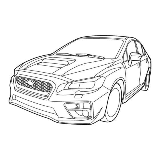
Table of contents Seat, seatbelt and SRS airbags Keys and doors Instruments and controls Climate control Audio Interior equipment Starting and operating Driving tips In case of emergency Appearance care Maintenance and service Specifications Supplement Index... - Page 13 Engine hood (page 11-12) Illustrated index Front wiper (page 3-107) Headlight (page 3-93) & Exterior Replacing bulbs (page 11-47) Sunroof (page 2-30) Door locks (page 2-4) Outside mirror (page 3-112) Tire pressure (page 11-36) Flat tires (page 9-5) 10) Tire chains (page 8-10) 11) Fog light (page 3-103) 12) Tie-down hooks (page 9-13) 13) Towing hook (page 9-13)
- Page 14 Rear window defogger (page 3-114) Fuel filler lid and cap (page 7-3) Child safety locks (page 2-24) Tie-down hole (page 9-13) Trunk lid (page 2-27) Towing hook (page 9-13) – CONTINUED –...
- Page 15 Anchor bars for ISOFIX child restraint & Interior system (page 1-35) Seatbelt (page 1-14) ! Passenger compartment area Front seat (page 1-2) Rear seat (page 1-10) Warning labels for child restraint system (page 1-25) SOS button for ERA-GLONASS system AIRBAG *: NEVER use a rearward facing child restraint on a seat protected by an ACTIVE AIRBAG in front of it, DEATH...
- Page 16 Center console (page 6-5) (STI) Seat heater (page 1-9) Cup holder (page 6-5) Parking brake lever (page 7-41) Power windows (page 2-24) Door locks (page 2-4) Outside mirror switch (page 3-112) Glove box (page 6-4) Front power supply socket (page 6-7) 10) Shift lever (page 7-12) 11) SI-DRIVE (page 7-25) 12) Driver s Control Center Differential...
- Page 17 Center console (page 6-5) (Except STI) Seat heater (page 1-9) Cup holder (page 6-5) Parking brake lever (page 7-41) Power windows (page 2-24) Door locks (page 2-4) Outside mirror switch (page 3-112) Glove box (page 6-4) Front power supply socket (page 6-7) 10) Shift lever (MT) (page 7-12)/Select lever (CVT) (page 7-20) The illustration above is a typical example for left-hand drive models.
-
Page 18: Instrument Panel
Illumination brightness control & Instrument panel (page 3-100) Headlight beam leveler (page 3-101) ! Left-hand drive models Trunk lid opener switch (page 2-27) Combination meter (page 3-9) Multi function display (page 3-47) Hazard warning flasher switch (page 3-8) Multi function display control switch (page 3-47) Audio (page 5-1) Climate control (page 4-1) - Page 19 Multi function display (page 3-47) ! Right-hand drive models Hazard warning flasher switch (page 3-8) Multi function display control switch (page 3-47) Audio (page 5-1) Climate control (page 4-1) Tilt/telescopic steering (page 3-115) Combination meter (page 3-9) Horn (page 3-116) SRS airbag (page 1-38) 10) Hood lock release knob (page 11-12) 11) Fuse box (page 11-46)
- Page 20 Audio control buttons (page 5-39) & Steering wheel Cruise control (page 7-45) Shift paddle (page 7-22) Hands-free switches (page 5-47)/Voice command system (page 5-62) Multi information display control switches (page 3-36) SRS airbag (page 1-38) Horn (page 3-116) SI-DRIVE switches (if equipped) (page 7-27) –...
- Page 21 Windshield wiper (page 3-107) & Light control and wiper control levers/switches Mist (page 3-107) ! Type A Windshield washer (page 3-110) Wiper intermittent time control switch (page 3-109)/Sensor sensitivity control (page 3-108) Wiper control lever (page 3-105) Light control switch (page 3-92) Fog light switch (page 3-103) Headlight ON/OFF/AUTO (page 3-93) Headlight flasher High/Low beam...
- Page 22 Windshield wiper (page 3-107) ! Type B Mist (page 3-107) Windshield washer (page 3-110) Wiper intermittent time control switch (page 3-109)/Sensor sensitivity control (page 3-108) Wiper control lever (page 3-105) Light control switch (page 3-92) Fog light switch (page 3-103) Headlight ON/OFF/AUTO (page 3-93) Headlight flasher High/Low beam change (page 3-95)
- Page 23 Tachometer (page 3-11) & Combination meter Multi information display (page 3-36) ! Except U.K. models Select lever/gear position indicator (page 3-33) Speedometer (page 3-9) Trip meter A/B selection and trip meter reset knob (page 3-10) Fuel gauge (page 3-11) Trip meter and odometer (page 3-10) Temperature gauge (page 3-12) The illustration above is a typical example.
- Page 24 Tachometer (page 3-11) ! U.K. models Multi information display (page 3-36) Select lever/gear position indicator (page 3-33) Speedometer (page 3-9) Trip meter A/B selection and trip meter reset knob (page 3-10) Fuel gauge (page 3-11) Trip meter and odometer (page 3-10) Temperature gauge (page 3-12) The illustration above is a typical example.
- Page 25 & Warning and indicator lights Mark Name Page Mark Name Page Mark Name Page Brake system warning High beam indicator 3-25 3-33 light light Seatbelt warning light 3-14 Vacuum pump system High Beam Assist in- 3-34 warning light (except 3-26 dicator light (green) STI) SRS airbag system...
- Page 26 3-24 differential indicator 3-35 (STI) REV indicator light Low fuel warning light 3-26 3-36 (STI) Low tire pressure SUBARU Rear Vehi- warning light (if 3-20 cle Detection warning 3-36 equipped) indicator (if equipped) SUBARU Rear Vehi- Windshield washer 3-26 3-36...
- Page 27 Function settings A SUBARU dealer can change the settings of the functions shown in the following table to meet your personal requirements. We recommend that you contact the nearest SUBARU dealer for details. If your vehicle is equipped with a multi function display, the settings for some of these functions can be changed using the display.
- Page 28 Item Function Possible settings Default setting One-touch lane changer Operation of the one-touch lane changer Operation/Non-operation Operation Headlight off delay setting Operation of timer OFF/30s/60s/90s 30 seconds High Beam Assist High Beam Assist function Operation/Non-operation Operation Emergency Stop Signal Emergency stop signal function Operation/Non-operation Operation : If equipped...
- Page 29 Seat, seatbelt and SRS airbags Front seats............Safety precautions ..........1-22 Where to place a child restraint system ....1-23 Manual seat ............Power seat (driver’s seat – if equipped) ....Choosing a child restraint system ...... 1-25 Installing child restraint systems with Head restraint adjustment........
-
Page 30: Front Seats
Seat, seatbelt and SRS airbags/Front seats Front seats used in the upright position in a collision, the risk of sliding under the lap belt and of the lap belt WARNING sliding up over the abdomen will increase, and both can result in . - Page 31 Seat, seatbelt and SRS airbags/Front seats Secure ALL types of child restraint devices (including forward facing child seats) in the REAR seats at all times. NEVER INSTALL A FORWARD OR REARWARD FACING CHILD SEAT IN THE FRONT SEAT. DOING SO RISKS SERIOUS INJURY OR DEATH TO THE CHILD BY PLACING THE CHILD’S HEAD TOO CLOSE TO THE...
-
Page 32: Manual Seat
Seat, seatbelt and SRS airbags/Front seats & Manual seat ! Reclining the seatback ! Seat cushion height adjustment (driver’s seat) ! Forward and backward adjustment Pull the reclining lever up and adjust the seatback to the desired position. Then When the lever is pushed down, the seat Pull the lever upward and slide the seat to is lowered. -
Page 33: Power Seat (Driver's Seat - If Equipped)
Seat, seatbelt and SRS airbags/Front seats & Power seat (driver’s seat – if ! Memory function (if equipped) adjusting mechanism. equipped) . When any unusual conditions or WARNING malfunctions occur during the retrieval of the seat position, stop . Never adjust the seat while driv- the retrieval of the seat position ing to avoid loss of vehicle con- by performing any of the follow-... - Page 34 Seat, seatbelt and SRS airbags/Front seats OFF position. neutral position (MT models). involving serious injury or death. . The select lever is in the P position (CVT models) or the shift lever is in the neutral position (MT models). 2. While holding the access key and 1.
-
Page 35: Head Restraint Adjustment
Seat, seatbelt and SRS airbags/Front seats NOTE ! Clearing the registered seat 3. Open the driver s door. . If a new position is registered for the position with access key (if A chirp sounds and the seat moves to the equipped) same button, the previously registered registered position. - Page 36 Seat, seatbelt and SRS airbags/Front seats NOTE To lower: proper positions in order to mini- mize the risk of neck injury in the Push the head restraint down while When the head restraint cannot be event of a crash. pressing the release button on the top of pulled out or installed due to insuffi- cient clearance between the head re- the seatback.
-
Page 37: Seat Heater (If Equipped)
Seat, seatbelt and SRS airbags/Seat heater To return: can cause battery discharge. Seat heater (if equipped) Tilt the head restraint once as far forward as it can go. The head restraint will The seat heater is equipped in the front automatically return to the fully upright seats. -
Page 38: Rear Seats
1-10 Seat, seatbelt and SRS airbags/Rear seats Rear seats HIGH/(HI) Rapid heating WARNING LOW/(LO) Normal heating Never stack luggage or other cargo Left-hand side WARNING higher than the top of the seatback Right-hand side because it could tumble forward and Seatbelts provide maximum re- To turn on the seat heater, push the LOW injure passengers in the event of a... -
Page 39: Head Restraint Adjustment
1-11 Seat, seatbelt and SRS airbags/Rear seats & Head restraint adjustment ! Rear windows side seating position Both the rear window side seats and the CAUTION rear center seat are equipped with head restraints. The head restraint is not intended to be used in the retracted position. -
Page 40: Folding Down The Rear Seatback
1-12 Seat, seatbelt and SRS airbags/Rear seats When the seats are not occupied, lower When the rear center seating position is the head restraints to improve rearward not occupied, lower the head restraint to visibility. improve rearward visibility. ! Rear center seating position &... - Page 41 1-13 Seat, seatbelt and SRS airbags/Rear seats WARNING When the seatback is returned to its original position, observe the follow- ing precautions. Failure to do so may lead to serious injury or an accident because the operation effi- ciency of the seatbelt is inhibited. .
-
Page 42: Seatbelts
1-14 Seat, seatbelt and SRS airbags/Seatbelts Seatbelts & Seatbelt safety tips WARNING . All persons in the vehicle should fasten their seatbelts BEFORE the vehicle starts to move. Other- wise, the possibility of serious injury becomes greater in the event of a sudden stop or acci- dent. - Page 43 1-15 Seat, seatbelt and SRS airbags/Seatbelts ! Infants or small children if damage is not obvious. their risk of being injured from deployment is greater. . When replacing a seatbelt, the Use a child restraint system that is new seatbelt must be type-ap- Secure ALL types of child re- suitable for your vehicle.
-
Page 44: Emergency Locking Retractor (Elr)
1-16 Seat, seatbelt and SRS airbags/Seatbelts & Emergency Locking Retrac- ! Expectant mothers extended. As the belt is rewinding, clicks will be heard which indicate the retractor tor (ELR) functions as an ALR. When the seatbelt is All seatbelts in the vehicle have an retracted fully, the ALR mode is canceled Emergency Locking Retractor (ELR). -
Page 45: Fastening The Seatbelt
1-17 Seat, seatbelt and SRS airbags/Seatbelts & Fastening the seatbelt If you do so, the risk of sliding has been closed up in sunny weath- under the lap belt and of the lap er; they could burn an occupant. Do belt sliding up over the abdomen not touch such hot parts until they WARNING... - Page 46 1-18 Seat, seatbelt and SRS airbags/Seatbelts ! Adjusting the front seat shoulder WARNING belt anchor height When wearing the seatbelts, make sure the shoulder portion of the webbing does not pass over your neck. If it does, adjust the seatbelt anchor to a lower position.
-
Page 47: Seatbelt Maintenance
1-19 Seat, seatbelt and SRS airbags/Seatbelts ! Rear seatbelts 1. Push the button on the buckle. 1. Sit well back in the seat. 2. Retract the seatbelt slowly to avoid the seatbelt being tangled or twisted. 2. Pick up the tongue plate and pull the belt out slowly. -
Page 48: Front Seatbelt Pretensioners
SUBARU parts by your authorized activated in the event of an accident harmful. This smoke does not indicate a SUBARU dealer. When using a seatbelt involving moderate to severe frontal colli- fire in the vehicle. equipped with a load limiter, it is sions. -
Page 49: System Monitors
. Satellite safing sensor: under the you consult your SUBARU deal- y o u c o n s u l t y o u r n e a r e s t rear center seat SUBARU dealer. -
Page 50: Precautions Against Vehicle Modification
& Precautions against vehicle & Safety precautions seating positions. modification We recommend that you consult your SUBARU dealer if you want to install any accessory parts to your vehicle. CAUTION Do not perform any of the following modifications. Such modifications can interfere with proper operation of the seatbelt pretensioners. -
Page 51: Where To Place A Child Restraint System
If the rear seatback is The following are SUBARU s recommen- not locked securely, serious injury dations on where to place a child restraint may result. - Page 52 1-24 Seat, seatbelt and SRS airbags/Child restraint systems . ISOFIX anchor bars WARNING . Top tether anchorages . Secure ALL types of child re- Some types of child restraints might not be straint devices (including for- able to be secured firmly due to projection ward facing child seats) in the of the seat cushion.
-
Page 53: Choosing A Child Restraint System
1-25 Seat, seatbelt and SRS airbags/Child restraint systems & Choosing a child restraint deployment of the front passen- ger’s SRS frontal airbag can system cause death or serious injury to the child in the event of an accident. ! Warning label WARNING . - Page 54 1-26 Seat, seatbelt and SRS airbags/Child restraint systems Child restraint suitability for each seating position (Europe) Group 0: for children of a mass less than Front seating position: 10 kg Mass group Suitability Group 0 : for children of a mass less than 13 kg up to 10 kg Group I: for children of mass from 9 to 18...
- Page 55 U: Suitable for universal category child restraint system. UF: Suitable for forward-facing universal category restraints approved for use in this mass group. 6: Not suitable for child restraint system. : Childseat SUBARU Baby Safe Plus : Childseat SUBARU Duo plus : Childseat SUBARU Kid Plus : Childseat SUBARU Kidfix XP –...
-
Page 56: Installing Child Restraint Systems With Seatbelt
6: ISOFIX position not suitable for ISOFIX child restraint systems in the mass group and/or this size class. NA: There is no ISOFIX system. IL1: Childseat G 0/1S ISOFIX and Childseat G 0/1S ISOFIX base IL2: Childseat SUBARU Duo plus IL3: Childseat SUBARU Kidfix XP... - Page 57 1-29 Seat, seatbelt and SRS airbags/Child restraint systems NOTE . When you install a child restraint If the ALR is equipped for the seatbelt, refer to Models with ALR F1-32. . If using the lock-off lever or the system, follow the manufac- turer’s instructions supplied with locking clip is recommended by the NOTE...
- Page 58 1-30 Seat, seatbelt and SRS airbags/Child restraint systems until you hear a click. press the release button on the seatbelt system is to be installed. buckle. 2. Place the child restraint system on the seat. WARNING NEVER INSTALL A FORWARD OR REARWARD FACING CHILD SEAT IN THE FRONT PASSENGER’S SEAT.
- Page 59 1-31 Seat, seatbelt and SRS airbags/Child restraint systems equipped with a lock-off (a seatbelt locking feature), secure the child restraint system using a locking clip. Lock-off lever Lock-off lever 5. Release the child restraint system 7. Lock the child restraint system lock-off lock-off lever and pass the shoulder belt lever to fix the shoulder belt.
- Page 60 1-32 Seat, seatbelt and SRS airbags/Child restraint systems NOTE ! Models with ALR If using ALR mode is not recom- mended by the manufacturer’s instruc- tions supplied with the child restraint system, use the lock-off lever or the locking clip instead of using ALR mode.
- Page 61 1-33 Seat, seatbelt and SRS airbags/Child restraint systems 5. Take up the slack in the lap belt. press the release button on the seatbelt buckle and allow the belt to retract 6. Pull out the seatbelt fully from the completely. The belt will return to the retractor to change the retractor over from ELR mode.
-
Page 62: Installing A Booster Seat
1-34 Seat, seatbelt and SRS airbags/Child restraint systems & Installing a booster seat seating position and sit the child on it. The WARNING child should sit well back on the booster . Never use a belt that is twisted or seat. -
Page 63: Installation Of Child Restraint Systems Using Isofix Anchor Bars
1-35 Seat, seatbelt and SRS airbags/Child restraint systems & Installation of child restraint the rear seat seatbacks. These marks indicate the positions of the ISOFIX systems using ISOFIX an- anchor bars. chor bars The ISOFIX anchor bars allow you to install a child restraint system only on the rear seat window-side seating positions. - Page 64 1-36 Seat, seatbelt and SRS airbags/Child restraint systems child restraint system to the anchor bars. The inserting aids make it easier to fit When the connectors are fastened, make the child restraint system with ISOFIX sure that the adjacent seatbelts are not and avoid damage to the seat.
-
Page 65: Top Tether Anchorages
1-37 Seat, seatbelt and SRS airbags/Child restraint systems vehicle, we recommend that you use a top CAUTION tether whenever one is required or avail- able. When you install a child restraint system, follow the manufacturer’s ! Anchorage location instructions supplied with it. After Anchorages are installed as shown in the installing the child restraint system, following illustration. -
Page 66: Seat, Seatbelt And Srs Airbags
We recommend that you contact your configurations are as follows. serious accident. SUBARU dealer if you have any question . Frontal airbags for driver and front Not wearing a seatbelt increases regarding the installation of a child re-... - Page 67 1-39 Seat, seatbelt and SRS airbags/*SRS airbag (Supplemental Restraint System airbag) the blink of an eye – and force to move the seat as far back as restraint device or in a seatbelt, protect in high speed collisions, possible and sit upright and well whichever is appropriate for the the force of an airbag can injure back in the seat.
- Page 68 1-40 Seat, seatbelt and SRS airbags/*SRS airbag (Supplemental Restraint System airbag) NOTE JURY OR DEATH TO THE CHILD . When you sell your vehicle, we urge BY PLACING THE CHILD’S HEAD TOO CLOSE TO THE SRS AIR- you to explain to the buyer that it is BAG.
-
Page 69: Components
1-41 Seat, seatbelt and SRS airbags/*SRS airbag (Supplemental Restraint System airbag) & Components The SRS airbags are stowed in the following locations. Driver’s SRS frontal airbag: in the center portion of the steering wheel An SRS AIRBAG mark is located on the steering pad. - Page 70 1-42 Seat, seatbelt and SRS airbags/*SRS airbag (Supplemental Restraint System airbag) Front sub sensor (right-hand side) SRS airbag system warning light Frontal airbag module (driver s side) Airbag control module (including impact sensor [all models] and rollover sensor [Russia models]) Frontal airbag module (front passenger s side) Front passenger s occupant detection...
- Page 71 1-43 Seat, seatbelt and SRS airbags/*SRS airbag (Supplemental Restraint System airbag) Front sub sensor (left-hand side) SRS airbag system warning light Frontal airbag module (driver s side) Airbag control module (including impact sensors) Frontal airbag module (front passenger s side) Front passenger s occupant detection control module* Front passenger s occupant detection...
-
Page 72: Srs Frontal Airbag
1-44 Seat, seatbelt and SRS airbags/*SRS airbag (Supplemental Restraint System airbag) & SRS frontal airbag WARNING Warning labels are located on both sides of the front passenger’s sun visor. Carefully read the description in “Warning label” F1-25. The driver s SRS frontal airbag is stowed in the center portion of the steering wheel. - Page 73 1-45 Seat, seatbelt and SRS airbags/*SRS airbag (Supplemental Restraint System airbag) airbag in front of it! . WARNING WARNING WARNING Never hold a child on your lap or in The SRS airbag deploys with con- your arms. The SRS airbag deploys siderable speed and force.
- Page 74 1-46 Seat, seatbelt and SRS airbags/*SRS airbag (Supplemental Restraint System airbag) . The key must not be attached to seatbelt to help avoid injuries that WARNING can result when the SRS airbag heavy, sharp or hard acces- contacts an occupant not in proper sories, or another key.
- Page 75 1-47 Seat, seatbelt and SRS airbags/*SRS airbag (Supplemental Restraint System airbag) system checked by your SUBARU dealer. sory power outlet and placed on the . If the SRS airbag system warning light front passenger’s seat or used by the person sitting in the front pas- does not illuminate, check that the front senger’s seat, may affect the opera-...
- Page 76 We recom- front passenger’s seat. mend that you have the system inspected . Do not place anything (shoes, by your SUBARU dealer immediately if the umbrella, etc.) under the front SRS airbag system warning light illumi- passenger’s seat.
- Page 77 Do not use the front passenger s seat serve the following precautions. while driving the vehicle to your SUBARU WARNING Failure to do so may interfere with dealer or another service center.
- Page 78 Seat, seatbelt and SRS airbags/*SRS airbag (Supplemental Restraint System airbag) ! If the front passenger’s frontal If the ON indicator still remains illuminated your SUBARU dealer for an inspection. airbag ON indicator illuminates while the OFF indicator turns off after...
- Page 79 2. Ask the front passenger to set the We recommend that you immediately seatback to the upright position, sit up contact your SUBARU dealer for an straight in the center of the seat cushion, inspection. correctly fasten the seatbelt, position his/ her legs out forward, and adjust the seat to the rearmost position.
- Page 80 1-52 Seat, seatbelt and SRS airbags/*SRS airbag (Supplemental Restraint System airbag) ! Operation The SRS airbag can function only when the ignition switch is in the ON position. If the front sub sensors located on both the right and left sides at the front of the vehicle and the impact sensors in the airbag control module detect a certain predetermined amount of force during a...
- Page 81 1-53 Seat, seatbelt and SRS airbags/*SRS airbag (Supplemental Restraint System airbag) situation, should it occur, the SRS airbag those situations. similar in fashion and magnitude to the will deflate quickly, not obscuring vision The SRS airbag is designed to function on collision described above.
- Page 82 1-54 Seat, seatbelt and SRS airbags/*SRS airbag (Supplemental Restraint System airbag) ! At what other times might the plunges into a deep ditch, is severely impacted or knocked hard against an SRS frontal airbag deploy? obstacle on the road such as a curb). The SRS frontal airbag may be activated when the vehicle sustains a hard impact in the undercarriage area from the road...
- Page 83 1-55 Seat, seatbelt and SRS airbags/*SRS airbag (Supplemental Restraint System airbag) The vehicle strikes an object, such as a ! When is the SRS frontal airbag unlikely to deploy? telephone pole or sign pole. The vehicle slides under the load bed of a truck.
-
Page 84: Srs Side Airbag And Srs Curtain Airbag
1-56 Seat, seatbelt and SRS airbags/*SRS airbag (Supplemental Restraint System airbag) & SRS side airbag and SRS ! When will the SRS frontal airbag in a low-speed frontal collision. curtain airbag not deploy? The SRS side airbag is stored in the door side of each front seat seatback. - Page 85 1-57 Seat, seatbelt and SRS airbags/*SRS airbag (Supplemental Restraint System airbag) door, and it provides protection WARNING by deploying rapidly (faster than the blink of an eye) in the event of The SRS side airbag and SRS a side impact collision. However, curtain airbag are designed only to the force of SRS side airbag be a supplement to the primary...
- Page 86 1-58 Seat, seatbelt and SRS airbags/*SRS airbag (Supplemental Restraint System airbag) back. In the event of an accident, WARNING the force of the SRS side airbag deployment could injure the child . Do not attach accessories to the seriously because his/her head door trim or near either SRS side or arms or other parts of the airbags and do not place objects...
- Page 87 SUBARU seat accident. Also, the SRS side airbag and predetermined level in a side collision, the...
- Page 88 1-60 Seat, seatbelt and SRS airbags/*SRS airbag (Supplemental Restraint System airbag) control module causes only the SRS airbags are also designed to deploy when CAUTION curtain airbag on the impacted side to the vehicle is in an extremely inclined inflate. state such as during a rollover.
- Page 89 1-61 Seat, seatbelt and SRS airbags/*SRS airbag (Supplemental Restraint System airbag) ! When will the SRS side airbag ! When will the SRS curtain airbag and SRS curtain airbag most most likely deploy? (Russia likely deploy? models) A severe side impact near the front seat activates the SRS side airbag and SRS curtain airbag.
- Page 90 1-62 Seat, seatbelt and SRS airbags/*SRS airbag (Supplemental Restraint System airbag) The vehicle is involved in an oblique ! When is the SRS side airbag unlikely to deploy? side-on impact. The vehicle is involved in a side-on impact in an area outside the vicinity of the passenger compartment.
- Page 91 1-63 Seat, seatbelt and SRS airbags/*SRS airbag (Supplemental Restraint System airbag) The vehicle is involved in an oblique ! When is the SRS curtain airbag unlikely to deploy? side-on impact. The vehicle is involved in a side-on Except Russia models impact in an area outside the vicinity of the passenger compartment.
- Page 92 1-64 Seat, seatbelt and SRS airbags/*SRS airbag (Supplemental Restraint System airbag) The vehicle is involved in an oblique Russia models side-on impact. The vehicle is involved in a side-on impact in an area outside the vicinity of the passenger compartment. The vehicle strikes a telephone pole or similar object.
-
Page 93: Srs Airbag System Monitor
1-65 Seat, seatbelt and SRS airbags/*SRS airbag (Supplemental Restraint System airbag) The vehicle pitches end over end. ! When will the SRS side airbag and SRS curtain airbag are activated on the first impact, they will not be activated The SRS side airbag and SRS curtain and SRS curtain airbag not de- on the second. -
Page 94: Srs Airbag System Servicing
. Curtain airbag sensor system checked immediately by injury. your nearest SUBARU dealer. Un- Rear wheel house right-hand side less checked and properly repaired, Rear wheel house left-hand side the seatbelt pretensioners and/or . -
Page 95: Precautions Against Vehicle Modification
In the following cases, we recommend control module, impact sensors inoperative, which may result in that you contact your SUBARU dealer and airbag modules are stored in serious injury, no modifications as soon as possible. - Page 96 Do not perform any of the following We recommend that you always consult modifications. Such modifications your SUBARU dealer if you want to install can interfere with proper operation any accessory parts on your vehicle. of the SRS airbag system.
-
Page 97: Keys And Doors
Keys and doors PIN Code Access (models with “keyless Keys ..............access with push-button start system”) ..2-17 Key number plate ..........Registering a PIN code ........2-17 Technical information for Europe models ..... Immobilizer ............Unlocking ............2-18 Remote keyless entry system......2-18 Immobilizer indicator light ........ -
Page 98: Keys
Keys and doors/Keys Keys relevant to each country (e.g., a copy of CAUTION the original Declaration of Conformity and the CE marking are required for the EU). NOTE Do not attach a large key holder or key case to the key. If it bangs For models with “keyless access with against your knees while you are push-button start system”, refer to... -
Page 99: Immobilizer
Keys and doors/Immobilizer & Ignition switch (models without push- Immobilizer Immobilizer indicator button start system) F3-4. light The immobilizer system is designed to Refer to Immobilizer indicator light F3- CAUTION prevent an unauthorized person from . Do not place the key under direct starting the engine. -
Page 100: Technical Information For Europe Models
Keys and doors/Door locks SUBARU dealer. Door locks switch (models without keyless access with push-button start system) or turn & Technical information for & Locking and unlocking from off the ignition switch (models with keyless access with push-button start Europe models the outside with key system). -
Page 101: Locking From The Outside Without Key
Keys and doors/Door locks & Locking from the outside ! Models with double locking system ! Models with double locking system without key To lock the doors from the outside with the It is not possible to place the lock lever on key, turn the key toward the front. -
Page 102: Battery Drainage Prevention Function
SUBARU dealer. We recommend that & Battery drainage prevention you contact your SUBARU dealer to function change the setting. If a door is not completely closed, the... -
Page 103: Key Lock-In Prevention Function (Except Models With Double Locking System)
SUBARU dealer. We recommend that you contact a SUBARU dealer for details. Access key (main) NOTE Access key (sub) Key number plate... -
Page 104: Safety Precautions
Keys and doors/Keyless access with push–button start system & Safety precautions Locking and unlocking by the remote keyless entry system can also be con- trolled with the buttons on the access key. WARNING For the engine starting procedure, refer to Starting and stopping engine (models If you wear an implanted pacemaker with push-button start system) F7-9. - Page 105 – Although you can replace the battery of the access key yourself, it is recommended that the battery be replaced by a SUBARU dealer to avoid the Antenna risk of damage at the time of replacement. – Do not get the access key wet.
- Page 106 F2-15. The setting can Doing so may cause malfunc- near wireless communication also be changed by a SUBARU dealer. tions. equipment such as a cell phone For more details, we recommend that – When the access key is placed –...
-
Page 107: Locking And Unlocking With "Keyless Access" Entry Function
For reregis- onds. tration of an access key, we recom- When the steering is locked, the initi- mend that you contact a SUBARU alization is completed. dealer. . For a spare access key, we recom- & Locking and unlocking with mend that you contact a SUBARU “keyless access”... - Page 108 ! How to use keyless access func- audible signal can be changed by your the keyless access function when the tions SUBARU dealer. We recommend that you access key is inside the vehicle. However, contact your SUBARU dealer for details. ! Keyless access function tips depending on the status of the access key .
- Page 109 2-13 Keys and doors/Keyless access with push–button start system ! Unlocking ! Opening trunk ! Locking Trunk lid opener button Carry the access key, and grip either of Door lock sensor (above and below) the front door handles. Carry the access key, and press the trunk Carry the access key, close all doors and lid opener button.
-
Page 110: Warning Chimes And Warning Indicator
You can then left in the operating range for 10 minutes SUBARU dealer. For more details, we touch the door lock sensor to lock the or longer while all doors are locked recommend that you contact a SUBARU doors. -
Page 111: Disabling Keyless Access Function
. The locking and unlocking function by the remote keyless entry system is not disabled. . The setting can also be changed at SUBARU dealers. For more details, we recommend that you contact a SUBARU dealer. . To start the engine while the func- tions are disabled, perform the proce- dure described in “Starting engine”... -
Page 112: When Access Key Does Not Operate Properly
2-16 Keys and doors/Keyless access with push–button start system – When disabling by operating the ! By operating the driver’s door 7. Within 10 seconds after step 6 is performed, close and open the driver s driver’s door: a chirp will not be 1. -
Page 113: Pin Code Access (Models With "Keyless Access With Push-Button Start System")
2-17 Keys and doors/PIN Code Access (models with “keyless access with push–button start system”) & Registering a PIN code ! Registration PIN Code Access (models with “keyless access with For example, to register 32468 as the ! Preparation PIN code, perform the following proce- push-button start system”) 1. -
Page 114: Unlocking
2-18 Keys and doors/Remote keyless entry system – when you want to change the PIN another person, confirm that the PIN Remote keyless entry system code has not been changed or deleted. code If the PIN code has been changed or &... -
Page 115: Locking And Unlocking Doors
. For models with “keyless access your SUBARU dealer. We recommend that you contact your SUBARU dealer with push-button start system”, the for details. Also, the setting of the door unlock selection function can be... -
Page 116: Opening Trunk Lid
The not properly closed. operational/non-operational setting for this . For models with “keyless access function can be changed by a SUBARU with push-button start system”, the dealer. front door will be unlocked if you grip... -
Page 117: Headlight Off Delay Setting (If Equipped)
This setting can be changed to OFF (no The trade, model and supplier s names of operation), 30 seconds, 60 seconds, or this device are as follows. 90 seconds at SUBARU dealers. For Models with tire pressure monitoring more details, we recommend that you system: contact a SUBARU dealer. -
Page 118: Double Locking System (If Equipped)
2-22 Keys and doors/Double locking system & To set double locking system ! Setting system using remote trans- Double locking system (if mitter equipped) ! Setting system using key 1. Remove the key from the ignition 1. Remove the key from the ignition switch (models without keyless access The double locking system is an anti-theft switch (models without keyless access... -
Page 119: To Cancel Double Locking System
2-23 Keys and doors/Double locking system & To cancel double locking ! Canceling system using remote direction. . Break one of the windows and climb system transmitter out through the window opening. Press the button on the access key or ! Canceling system using key button on the transmitter. -
Page 120: Child Safety Locks
2-24 Keys and doors/Child safety locks Child safety locks Windows procedure could result in injury to a child operating the power window. WARNING The power windows operate only when the ignition switch is in the ON position. To avoid serious personal injury caused by accidental, child’s mis- chief, or improper operation, the driver is responsible for obeying... -
Page 121: Power Window Operation By Driver
2-25 Keys and doors/Windows & Power window operation by ! Operating the window This switch also has a one-touch auto up function that allows the window to be driver closed fully without holding the switch. ! Driver’s side power window Pull the switch up until it clicks and release switches it, and the window will fully close. - Page 122 2-26 Keys and doors/Windows NOTE ! Locking the passengers’ windows be sure to initialize the power windows. . If a window detects an impact simi- If they are not initialized, the one-touch auto up/down function will not operate. lar to that caused by trapping an object Refer to “Initialization of power win- (for example, when the vehicle encoun- dow”...
-
Page 123: Power Window Operation By Passengers
2-27 Keys and doors/Trunk lid ! Anti-entrapment function & Power window operation by Trunk lid Refer to Anti-entrapment function F2- passengers ! Passenger’s side power window WARNING & Initialization of power win- switches . To prevent dangerous exhaust gas from entering the vehicle, If the vehicle s battery is disconnected due always keep the trunk lid closed to situations such as battery or fuse... -
Page 124: To Open And Close The Trunk Lid From Outside
2-28 Keys and doors/Trunk lid & To open and close the trunk & To open the trunk lid from handle is located on the inside of the trunk lid. lid from outside inside The trunk lid can be opened using the keyless access function or remote keyless entry system. - Page 125 2-29 Keys and doors/Trunk lid ! Inspection handle. If the driver starts the vehi- cle without knowing that a child is Perform the following steps at least twice inside the trunk and the child opens a year to check the release handle for the lid using the release handle, the correct operation.
-
Page 126: Sunroof (If Equipped)
. If the sunroof does not close, we exception. recommend that you have the . Before closing the sunroof, make system checked by a SUBARU sure that no one’s hands, arms, dealer. head or other objects will be accidentally caught in the sun- The sunroof has both tilting and sliding roof. -
Page 127: Sunroof Switches
2-31 Keys and doors/Sunroof & Sunroof switches pletely. Pressing the switch continuously rear side of the switch again to open the may cause damage to the sunroof. sunroof completely. ! Tilting sunroof NOTE To close: Press the front side of the OPEN/CLOSE One-touch operation does not take switch. -
Page 128: Sun Shade
2-32 Keys and doors/Sunroof CAUTION Never attempt to test this function using fingers, hands or other parts of your body. NOTE For the sake of safety, it is recom- mended that you avoid driving with the sunroof fully opened. & Sun shade The sun shade can be slid forward or backward by hand while the sunroof is closed. -
Page 129: Instruments And Controls
Instruments and controls Ignition switch (models without push- Seatbelt warning light and chime ....... 3-14 button start system)......... Rear seatbelt indicator light and chime (if equipped) ............3-16 LOCK..............SRS airbag system warning light......3-17 ACC..............Front passenger’s frontal airbag ON and OFF ON.............. - Page 130 SUBARU Rear Vehicle Detection warning Headlight flasher ..........3-98 indicator (if equipped) ........3-36 Daytime running light system (if equipped)..3-99 SUBARU Rear Vehicle Detection OFF indicator (if Turn signal lever ..........3-99 equipped)............3-36 One-touch lane changer ........3-99...
- Page 131 Instruments and controls Illumination brightness control ....... 3-100 Headlight washer (if equipped)....... 3-111 Headlight beam leveler (if equipped) ....3-100 Mirrors .............. 3-111 Automatic headlight beam leveler (models with Inside mirror............. 3-111 LED headlights)..........3-100 Auto-dimming mirror (if equipped)....3-112 Manual headlight beam leveler (models without Outside mirrors ..........
-
Page 132: Ignition Switch (Models Without Push- Button Start System)
Instruments and controls/Ignition switch (models without push–button start system) Ignition switch (models with- long time with the ignition switch in the against your knees while you are “ON” or “ACC” position can cause the driving, it could turn the ignition out push-button start sys- switch from the “ON”... -
Page 133: Acc
Instruments and controls/Ignition switch (models without push–button start system) lever is in the P position (CVT models) START position and again try to start and the key is pushed in while turning it your engine. (all models). NOTE & ACC The engine may not start in the follow- ing cases: In this position the electrical accessories... -
Page 134: Ignition Switch Light
Instruments and controls/Push–button ignition switch (models with push–button start system) & Ignition switch light . Even when the access key is outside Push-button ignition switch the vehicle, if it is placed too close to (models with push-button For easy access to the ignition switch in the glass, it may be possible to switch the dark, the ignition switch light illumi- start system) -
Page 135: Switching Power Status
We recommend that you contact a SUBARU deal- er immediately. Power Indicator color Operation . If the push-button ignition switch... -
Page 136: Hazard Warning Flasher
Instruments and controls/Hazard warning flasher & When access key does not NOTE Hazard warning flasher . In CVT models, the push-button operate properly ignition switch cannot be switched to Refer to Access key if access key does “OFF” when the select lever is in a not operate properly F9-17. -
Page 137: Meters And Gauges
Instruments and controls/Meters and gauges & Canceling the function for . If you depress the brake pedal Meters and gauges suddenly, the hazard warning flasher meter/gauge needle move- may blink rapidly. For details, refer to NOTE ment upon turning on the “Emergency Stop Signal”... -
Page 138: Odometer
3-10 Instruments and controls/Meters and gauges & Odometer & Double trip meter Also, if you open and close the driver s door within 10 seconds of illumination of the odometer/trip meter, the odometer/trip meter will turn off. The display can be switched as shown in the following sequence by pressing the trip knob. -
Page 139: Tachometer
3-11 Instruments and controls/Meters and gauges & Tachometer & Fuel gauge the amount of fuel remaining in the tank, you (a) do not press the trip knob for 10 The tachometer shows the engine speed seconds or (b) open and close the driver s in thousands of revolutions per minute. -
Page 140: Temperature Gauge
3-12 Instruments and controls/Meters and gauges & Temperature gauge . The gauge indicates only an approx- CAUTION imate amount of fuel remaining in the tank. Use this indication only as a If the pointer exceeds the normal guide. operating range, safely stop the . -
Page 141: Rev Indicator Light And Buzzer (Sti)
3-13 Instruments and controls/REV indicator light and buzzer (STI) ever the engine speed enters the red REV indicator light and buz- Needle position zone of the tachometer. zer (STI) Displayed unit + side - side To change the REV indicator light settings, l/100km Poorer Better... -
Page 142: Warning And Indicator Lights
We recommend that you consult your : Brake system warning light seconds or after the engine has started. authorized SUBARU dealer for repair. : Low fuel warning light : Seatbelt warning light &... - Page 143 3-15 Instruments and controls/Warning and indicator lights ! Seatbelt warning for front passen- sounding for 5 seconds followed by a 1- second pause. If the seatbelt is fastened ger’s seat (if equipped) at this time, the warning light will turn off Your vehicle is equipped with a seatbelt and the buzzer will stop sounding imme- warning device for the front passenger s...
-
Page 144: Rear Seatbelt Indicator Light And Chime (If Equipped)
3-16 Instruments and controls/Warning and indicator lights mph) with the front passenger s seatbelt If the driver s seatbelt and/or the front 30 seconds have elapsed after the vehicle not fastened, the warning light(s) will start passenger s seatbelt is still not fastened started moving or the rear seatbelts have a repeated cycle consisting of 5 seconds when the 108-second period has elapsed,... -
Page 145: Srs Airbag System Warning Light
With the ignition switch turned to the ON have the system checked immedi- position, if both the ON and OFF indica- ately by your nearest SUBARU deal- tors remain illuminated or off simulta- er. Unless checked and properly neously even after the system check repaired, the seatbelt pretensioners period, the system is malfunctioning. -
Page 146: Malfunction Indicator Light (Check Engine Light)
! Models equipped with OBD system vehicle checked/repaired by your Vehicles sold in Europe are equipped with SUBARU dealer as soon as possi- The malfunction indicator light may stop an enhanced on-board diagnostics sys- ble. Continued vehicle operation blinking and illuminate steadily after sev-... -
Page 147: Oil Pressure Warning Light
SUBARU dealer. warning light turns off. illuminated, we recommend that you con- ! Transmission control system warn- tact your nearest SUBARU dealer imme- NOTE diately. . After replacing or adding engine oil, For details about checking the oil level or... -
Page 148: Rear Differential Oil Temperature Warning Light (Sti)
SUBARU dealer for service. inflation pressure label. For how to change and it is the driver s responsibility to a mode and information about the mode to... - Page 149 We recommend Your vehicle has also been equipped with If this light does not illuminate that you contact your SUBARU deal- a TPMS malfunction indicator to indicate briefly after the ignition switch is er as soon as possible for tire and when the system is not operating properly.
-
Page 150: Abs Warning Light
. The warning light illuminates when CAUTION your SUBARU dealer. the ignition switch is turned to the The Vehicle Dynamics Control sys- – The warning light does not “ON” position and turns off approxi-... - Page 151 We recommend that you SUBARU dealer immediately. have your vehicle checked at a SUBARU . The warning light does not illuminate dealer as soon as possible. when the ignition switch is turned to the .
-
Page 152: Vehicle Dynamics Control Off Indicator Light/Traction Mode Indicator Light
The Vehicle Dynamics Control system is probably malfunctioning under the follow- ing conditions. Have your vehicle checked at a SUBARU dealer as soon as possible. . The light does not illuminate when the ignition switch is turned to the ON... -
Page 153: Brake System Warning Light (Red)
We recommend that you have may be malfunctioning. This indicates your brake system the vehicle towed to the nearest SUBARU We recommend that you drive carefully to may not be working properly. If dealer for repair. For details, refer to... -
Page 154: Vacuum Pump System Warning Light (Yellow) (Except Sti)
MIN mark, the EBD system may be WARNING malfunctioning. We recommend that you This light does not turn off unless the drive carefully to the nearest SUBARU tank is replenished up to an internal When the Hill start assist warning dealer and have the system inspected. -
Page 155: All-Wheel Drive Warning Light (If Equipped)
SUBARU dealer and have the tion of the power steering control vehicle inspected immediately. NOTE system. -
Page 156: Led Headlight Warning Light (If Equipped)
We recommend that you WARNING may be provided depending on the have your vehicle inspected at a SUBARU status of the access key and the Never drive the vehicle if the indi- dealer as soon as possible. - Page 157 3-29 Instruments and controls/Warning and indicator lights Operation indicator Inside warning Outside warning on push-button igni- Status Action chime chime tion switch Switch the push-button ignition switch to The driver s door is opened while the OFF , or close the driver s door. push-button ignition switch is ACC (in *When exiting the vehicle, be sure to CVT models, when the select lever is in...
- Page 158 3-30 Instruments and controls/Warning and indicator lights Operation indicator Inside warning Outside warning on push-button igni- Status Action chime chime tion switch Power warning: Open the door and return the access key inside the vehicle, or switch the push- The door lock sensor is touched while Long beep (60 button ignition switch to OFF .
- Page 159 We recommend that you contact a System malfunction warning: SUBARU dealer immediately and have Ding Flashes in orange A malfunction was detected in the power the vehicle inspected.
-
Page 160: Immobilizer Indicator Light
Immobilizer indicator “ON” position ing. We recommend that you contact your light nearest SUBARU dealer immediately. . Even if a malfunction occurs, such This light begins flashing under any of the In the event that an unauthorized key (for as the immobilizer indicator light following conditions. -
Page 161: Shift-Up Indicator (Sti Without Gear Shift Indicator Models)
3-33 Instruments and controls/Warning and indicator lights & & Select lever/gear position in- ! Gear shift indicator (if equipped) Shift-up indicator (STI dicator (if equipped) without gear shift indi- When shifting up is recommended for cator models) good fuel economy, the upshift indicator blinks. -
Page 162: High Beam Assist Indicator Light (Green) (If Equipped)
& AUTO position and the headlights illumi- High Beam Assist in- commend that you have your vehi- nate automatically (models with auto on/ cle inspected at a SUBARU dealer dicator light (green) (if off headlights) as soon as possible. equipped) &... - Page 163 We recommend that you have the vehicle inspected by your ferential auto [−] indicator When you select the manual mode of the SUBARU dealer. For details, refer to (STI) driver s control center differential, the Driver s Control Center Differential (C.
-
Page 164: Warning (Sti)
When this indicator accident. appears, have your vehicle inspected by your SUBARU dealer as soon as possible. Various information will be shown on the & multi information display. Also, a warning... -
Page 165: Basic Operation
3-37 Instruments and controls/Multi information display & Welcome screen Warning indicator toward you. Select lever/gear position indicator (refer to Select lever/gear position indicator & Basic operation F3-33.) SI-DRIVE indicator (refer to SI-DRIVE By operating of the control indicator F3-32.) switch, the screens and selection items Odometer (refer to Odometer F3-10.)/ can be switched. -
Page 166: Good-Bye Screen
3-38 Instruments and controls/Multi information display & Warning screen on or off. For details, refer to “Welcome Good-bye Screen” F3-46. & Good-bye screen Example of warning If a warning or a malfunction is detected, a message will appear. Take the appropriate actions based on the messages indicated. - Page 167 3-39 Instruments and controls/Multi information display ! Items of display message (for warning message) Item Icon information reminder Refer to page Driver s seatbelt warning 3-14 SRS airbag system malfunction warning 1-65, 3-17 Engine warning Yellow 3-18 Coolant temperature high warning 3-12, 9-12 Engine low oil level warning (except STI) Yellow...
- Page 168 Item Icon information reminder Refer to page Vehicle Dynamics Control system malfunction warning Yellow 3-22 SUBARU Rear Vehicle Detection system halt or warning indicator Yellow 3-36 (if equipped) Parking brake applied warning 3-25 Electronic Brake Force Distribution system malfunction warning...
- Page 169 3-41 Instruments and controls/Multi information display Item Icon information reminder Refer to page Automatic headlight beam leveler system malfunction warning Yellow 3-27 (models with LED headlights) LED low beam headlight system malfunction warning (if equipped) Yellow 3-28 High Beam Assist warning indicator (if equipped) Yellow 3-34 The keyless access with push-button start system malfunction...
- Page 170 3-42 Instruments and controls/Multi information display ! Items of display message (for operation and vehicle condition) Item Icon information reminder Refer to page Deactivation of the selection of the SI-DRIVE Sport Sharp (S#) 7-25 mode when the engine is cold Pedal operation for starting engine Select lever into P operation Access key warning* (The vehicle was driven while the access key...
-
Page 171: Basic Screens
3-43 Instruments and controls/Multi information display & Basic screens Journey time screen: SI-DRIVE mode screen: By operating the switch on the steering wheel, you can change the screen that is always displayed. Default screen: This screen displays the journey time (the This screen indicates the current SI-DRIVE time that has elapsed since the ignition switch mode with its throttle angle. -
Page 172: Menu Screens
3-44 Instruments and controls/Multi information display & Menu screens Pull and hold the /SET switch to enter the menu screens when all of the following conditions are satisfied. . The vehicle has been completely stopped. . The select lever is in the P position (CVT models). - Page 173 3-45 Instruments and controls/Multi information display The menu list is as follows. Top menu Menu option Possible settings Initial settings Screen Settings Welcome Good-bye Screen On or Off Gauge Initial Movement On or Off Gear Position Indicator Setting (MT On or Off without gear shift indicator models) Languages Select the display language.
- Page 174 3-46 Instruments and controls/Multi information display ! SRVD (Subaru Rear Vehicle Detec- By operating the switch on the activate display of the shift position in- tion) (if equipped) steering wheel, you can select the menu. dicator or Off to deactivate it.
-
Page 175: Multi Function Display
3-47 Instruments and controls/Multi function display The multi function display has the follow- Multi function display ing functions. Description Page WARNING Displays useful messages, such 3-50 as warning information, etc. Always pay adequate attention to safe driving when operating the Displays basic screens (e.g. -
Page 176: Basic Operation
3-48 Instruments and controls/Multi function display & Basic operation & Welcome screen & Date screen When the door is unlocked and the If you have set the date and time in the driver s door is closed, the welcome selection screen, after the welcome screen will appear for a short time. -
Page 177: Ending Screen
3-49 Instruments and controls/Multi function display & Self-check screen NOTE . Displaying the birthday/anniversary When the ignition switch is turned to the screen can be set to on or off. Refer to ON position, the vehicle self-check will “Bypass screen setting” F3-77. be performed. -
Page 178: Interruption Screen
3-50 Instruments and controls/Multi function display & Interruption screen following conditions. – The period of time remaining Useful messages, such as reminder in- until the registered notification date formation, vehicle information, warning is 15 days or less. information, etc. may interrupt the current –... - Page 179 3-51 Instruments and controls/Multi function display & Basic screens ! Information bar These are the basic screens of the multi function display. Item Page Information bar 3-51 Boost pressure + accelerator 3-52 opening ratio screen Fuel consumption screen 3-53 ECO history screen 3-53 Vehicle activation status 3-54...
- Page 180 3-52 Instruments and controls/Multi function display ! Clock ! Boost pressure + accelerator temperature has increased to 58C (418F) or higher. opening ratio screen The clock can be displayed in either 12- hour display or 24-hour display. For details ! Top display about the setting, refer to Current date One of the following items can be dis- and time setting F3-61.
- Page 181 3-53 Instruments and controls/Multi function display ! Fuel consumption screen ! ECO history screen ! The peak value of the boost pressure resetting Pressing the button in the Boost pressure + accelerator opening ratio screen moves to a screen where you can reset the peak value of the boost pressure.
- Page 182 3-54 Instruments and controls/Multi function display Time range Width of bar graph 30 minutes 1 minute 60 minutes 2 minutes 4 minutes 120 minutes For details about the setting, refer to Economy history setting F3-74. ! Vehicle activation status screen When the vehicle is being driven regularly When the Vehicle Dynamics Control sys- tem activates, the tires illuminate in yellow...
- Page 183 3-55 Instruments and controls/Multi function display ! Triple meter screen ! Guidance screen Item Details Average vehicle speed (Average vehicle speed for the entire driving time from when the trip meter was reset) Lifetime fuel consumption Engine oil temperature (except STI) Accelerator opening ratio Journey distance (the distance...
- Page 184 3-56 Instruments and controls/Multi function display ! Clock/calendar/screen OFF Calendar Today s date Clock (type A) Birthday/Anniversary/Scheduled mainte- nance date In addition to the clock/calendar, the out- side temperature and average fuel con- sumption can also be displayed. You can select clock (type A), clock (type B) or calendar.
-
Page 185: Selection Screen
3-57 Instruments and controls/Multi function display & Selection screen When the button is pushed and held, the setting screen for each menu can be displayed. Select the preferred menu by operating switch. Top menu Menu option Description Initial setting Page Time/Date 1/1/20XX 12 h Time/Date... - Page 186 3-58 Instruments and controls/Multi function display Top menu Menu option Description Initial setting Page Screen Set and customize the top display information Avg Cons, Inst Cons, Range Top Display Avg Cons 3-72 Setting contents. or Off Upper part: Fuel consumption, Cons Customize the fuel consumption information display.
- Page 187 3-59 Instruments and controls/Multi function display Top menu Menu option Description Initial setting Page Mainte- Engine Oil Set and adjust the oil maintenance notification date. 3-80 The default va- nance lues for the main- Oil Filter Set and adjust the oil filter maintenance notification date. 3-82 tenance settings vary depending...
- Page 188 3-60 Instruments and controls/Multi function display Top menu Menu option Description Initial setting Page Hazard Warning Set the hazard warning flasher. On or Off 3-85 Setting Flasher Set and customize the automatic locking 20, 30, 40, 50, 60 seconds or Security Relocking 30 seconds 3-86...
-
Page 189: Date And Time Settings
3-61 Instruments and controls/Multi function display & Date and time settings The items in the date and time settings can be set. To change the items, operate switch. NOTE . The “Time/Date” item must be set to display the “Birthday”, “Anniversary” and notifications for vehicle mainte- nance. - Page 190 3-62 Instruments and controls/Multi function display 5. After entering the date and time, select Set by operating the switch and confirm the setting by pushing the button. 4. Select a number by operating the 2. Operate the switch to switch, and then push the select the Birthday item, and then push button.
- Page 191 3-63 Instruments and controls/Multi function display English alphabet (upper case charac- ters and lower case characters are available), eleven symbols or blank spaces. The word being edited will be displayed with an underline. 4. The selected item will be shown. Push 6.
- Page 192 3-64 Instruments and controls/Multi function display be deactivated. ! Anniversary setting 1. Perform the preparation steps accord- ing to Preparation for date setting F3- From 1 to 7 days prior to the birthday 9. The system will notify you that the setting is complete.
- Page 193 3-65 Instruments and controls/Multi function display 3. Select an entry in the list to set by 5. Select numbers by operating the 7. Select characters by operating the operating the switch, and then switch, and then push the switch, and then push the push the button.
- Page 194 3-66 Instruments and controls/Multi function display If an anniversary is approaching, the following screen will be displayed accom- panied by a beep when the ignition switch has been turned to the ON position. This function can be set to on or off. For details, refer to Bypass screen setting F3-77.
- Page 195 3-67 Instruments and controls/Multi function display ! Daylight saving time setting 1. Perform the preparation steps accord- ing to Preparation for date setting F3- 3. The current setting will be displayed. 5. Select Set by operating the Push the button to enter the selection switch, and confirm the setting by pushing mode.
- Page 196 3-68 Instruments and controls/Multi function display ! Delivery date setting (Australia models) 1. Perform the preparation steps accord- ing to Preparation for date setting F3- 3. The current setting will be displayed. 5. Select Set by operating the Push the button to enter the setting switch, and confirm the setting by pushing mode.
-
Page 197: Image Quality And Volume Settings
3-69 Instruments and controls/Multi function display & Image quality and volume ! Contrast setting settings 1. Perform the preparation steps accord- The items in the image quality and volume ing to Preparation for image quality and volume settings F3-69. settings can be set. To change the items, operate the switch. - Page 198 3-70 Instruments and controls/Multi function display 3. Select a contrast level by operating the 2. Operate the switch to 4. The screen will be turned off. switch, and confirm the setting select the Screen OFF item, and then by pushing the button.
-
Page 199: Screen Settings
3-71 Instruments and controls/Multi function display 2. Operate the switch to 4. Select an item by operating the 6. The system will notify you that the select the Beep item, and then push the switch, and then push the button. setting is complete. - Page 200 3-72 Instruments and controls/Multi function display 3. After the selection screen is displayed, 2. Operate the switch to 4. Select an item by operating the operate the switch to show the select the Top Display item, and then switch, and then push the button.
- Page 201 3-73 Instruments and controls/Multi function display 6. The system will notify you that the 2. Operate the switch to 4. Select the displayed configuration by setting is complete. select the Cons item, and then push the operating the switch, and then button.
- Page 202 3-74 Instruments and controls/Multi function display 6. The system will notify you that the 2. Operate the switch to 4. Select the time of the logged fuel setting is complete. select the Eco History item, and then consumption history by operating the push the button.
- Page 203 3-75 Instruments and controls/Multi function display ! Triple meter setting 1. Perform the preparation steps accord- ing to Preparation for screen settings F3-71. 6. Select Set by operating the 3. Select the setting location (left, center switch and confirm the setting by pushing or right) by operating the button.
- Page 204 3-76 Instruments and controls/Multi function display switch, and confirm the setting by pushing button. 4. Select the preferred item by operating 2. Operate the switch to switch, and then push the select the Clock item, and then push the button. button.
- Page 205 3-77 Instruments and controls/Multi function display 4. Select Type A clock , Type B clock , 6. The system will notify you that the 2. Operate the switch to Calendar or OFF by operating the setting is complete. select the Bypass Screen item, and then switch and then push the button.
- Page 206 3-78 Instruments and controls/Multi function display switch, and confirm the setting by pushing the button. 4. Select On or Off by operating the 2. Operate the switch to switch, and push the select the Languages item, and then button. push the button.
- Page 207 3-79 Instruments and controls/Multi function display 4. Select the preferred language by 6. The system will notify you that the 2. Operate the switch to operating the switch, and then setting is complete. select the Side View Monitor item, and push the button.
-
Page 208: Maintenance Settings
3-80 Instruments and controls/Multi function display 4. Select an item by operating the 6. The system will notify you that the 3. After the selection screen is displayed, switch, and then push the setting is complete. operate the switch to show the button. - Page 209 3-81 Instruments and controls/Multi function display switch and confirm the setting by pushing the button. 2. Operate the switch to 4. Select a number by operating the select the Engine Oil item, and then push switch, and then push the button.
- Page 210 3-82 Instruments and controls/Multi function display “0000” for the next 500 km (311 miles). After exceeding 500 km (311 miles), “_ _ _ _” will be displayed. ! Oil filter setting The setting procedure is the same as Engine oil setting F3-80, but select the Oil Filter item in step 2.
- Page 211 3-83 Instruments and controls/Multi function display operating the switch. 6. The system will notify you that the 2. Operate the switch to setting is complete. select the Clear All Settings item, and 4. Confirm the setting by pushing the then push the button.
-
Page 212: Driving History Registration
3-84 Instruments and controls/Multi function display & Driving history registration The items in the driving history can be registered. To change the items, operate switch, and then push the button. 1. Turn the ignition switch to the ON position. 2. Push and hold the button to show the selection screen. -
Page 213: Car Settings
3-85 Instruments and controls/Multi function display ! Hazard warning flasher setting tered directly without a notification. 3. The current setting will be displayed. Push the button to enter the selection 1. Perform the preparation steps accord- 8. The system will notify you that the ing to Preparation for car settings F3-85. - Page 214 3-86 Instruments and controls/Multi function display 5. Select Set by operating the then push the button. switch, and confirm the setting by pushing button. ! Security Relocking 3. The current setting will be displayed. 1. Perform the preparation steps accord- Push the button to enter the selection ing to Preparation for car settings F3-85.
- Page 215 3-87 Instruments and controls/Multi function display button. If the setting is not available, the following notification will be displayed. In this case, perform the setting procedure again. 2. Operate the switch to select the Defogger item, and then push 5. Select Set by operating the button.
- Page 216 3-88 Instruments and controls/Multi function display ! Interior light off delay timer setting 1. Perform the preparation steps accord- ing to Preparation for car settings F3-85. 4. Select the preferred setting by operat- 6. The system will notify you that the ing the switch, and then push setting is complete.
-
Page 217: Initialize
3-89 Instruments and controls/Multi function display 3. The current setting will be displayed. 5. Select Set by operating the Push the button to enter the selection switch, and confirm the setting by pushing mode. button. & Initialize Items that have been set to your pre- ference can be initialized. - Page 218 3-90 Instruments and controls/Multi function display by operating the switch. 3. After the selection screen is displayed, 2. Operate the switch to operate the switch to show the select the Reset to Defaults item, and 4. Confirm the setting by pushing the Initialize item.
- Page 219 3-91 Instruments and controls/Multi function display ! Lifetime fuel consumption resetting 1. Perform the preparation steps accord- ing to Preparation for initialization F3- 3. The system will prompt a Yes/No 5. Reconfirmation will be displayed. If dialogue ( No is selected first). To reset you are sure you want to proceed, select the lifetime fuel consumption, select Yes Yes by operating the...
-
Page 220: Light Control Switch
3-92 Instruments and controls/Light control switch Light control switch Regardless of the position of the light control switch, the illuminated lights are turned off when the key is removed from CAUTION the ignition switch. . Use of any lights for a long period NOTE of time while the engine is not The light control switch can be oper-... -
Page 221: Headlights
The sensitivity of the auto on/off head- lights can be changed by your Australia models SUBARU dealer. We recommend that Second position Except Australia models you contact your SUBARU dealer for First position Second position details. Auto position (if equipped) First position... - Page 222 This setting can be changed to OFF (no cess with push-button start system ). operation), 30 seconds, 60 seconds, or NOTE 90 seconds at SUBARU dealers. For . While the headlight off delay func- more details, we recommend that you contact a SUBARU dealer.
-
Page 223: High/Low Beam Change (Dimmer)
– Do not modify the vehicle. order to operate the High Beam Assist function properly. – Always replace the windshield glass with genuine SUBARU parts (or equivalent products). To change from low beam to high beam, push the turn signal lever forward. When –... - Page 224 (non-operation) at SUBARU dealers. low) For more details, we recommend that When the High Beam Assist function you contact a SUBARU dealer. malfunctions, the High Beam Assist warn- ing indicator (yellow) on the combination meter will appear. In this case, we recommend that you have your vehicle inspected by your SUBARU dealer.
- Page 225 If the headlights of an oncoming inspected at a SUBARU dealer. ahead of your vehicle, etc. Therefore, the vehicle or the tail lights of a vehicle headlight mode may switch in some...
-
Page 226: Headlight Flasher
. This function can be disabled at front fog lights of an oncoming vehicle, the headlight mode may change from the high SUBARU dealers. For more details, we beam to the low beam automatically. CAUTION recommend that you contact a SUBARU . -
Page 227: Daytime Running Light System (If Equipped)
AUTO (if equipped) or off position. To activate the right turn signal, push the changed by a SUBARU dealer. We NOTE turn signal lever up. To activate the left recommend that you contact the nearest . -
Page 228: Illumination Brightness Control
3-100 Instruments and controls/Illumination brightness control Illumination brightness con- celed even when the ignition switch is Headlight beam leveler (if turned to the “LOCK”/“OFF” position. trol equipped) & Automatic headlight beam leveler (models with LED headlights) The LED headlights generate more light than conventional halogen headlights. -
Page 229: Manual Headlight Beam Leveler (Models Without Led Headlights)
3-101 Instruments and controls/Headlight beam leveler & Manual headlight beam leve- ler (models without LED headlights) Raises the level of the headlight beam Lowers the level of the headlight beam Adjust the headlight beam level with the following dial positions according to the number of passengers and load condition. - Page 230 3-102 Instruments and controls/Headlight beam leveler Number of front seat Number of rear seat Load in the luggage Dial position occupants occupants compartment area 1 or 2 No load No load Full load* Full load* Full load* Full load* 3, 4 and 5 Use in special case Use in special case Use in special case...
-
Page 231: Fog Light Switch
3-103 Instruments and controls/Fog light switch switch back down to the following posi- Fog light switch tions. & Front fog light switch (if position (except Australia models) equipped) OFF position (Australia models) Front fog light operating condition (Australia models) Headlight switch Fog light switch The front fog lights will turn on when the Front fog light operating condition... -
Page 232: Rear Fog Light Switch (If Equipped)
3-104 Instruments and controls/Fog light switch & Rear fog light switch (if position when released. equipped) position (models with front fog lights) position (models without front fog lights) To turn off the rear fog light, perform either of the following procedures. . -
Page 233: Wiper And Washer
Before operating the wiper washer fluid is unavailable. In on a dry windshield or rear areas where water freezes in window, always use the wind- winter, use SUBARU Windshield shield washer. Washer Fluid or the equivalent. – CONTINUED –... - Page 234 3-106 Instruments and controls/Wiper and washer Refer to “Windshield washer and the wiper blades using a sponge or they may operate unexpectedly fluid” F11-41. soft cloth with a neutral detergent or and car wash brushes could mild-abrasive cleaner. After cleaning, become tangled around them.
-
Page 235: Windshield Wiper And Washer Switches
If necessary, turn the wiper switch to any position except for the “AUTO” position. We recommend that you contact your SUBARU dealer and have the system inspected as soon Except Australia models as possible. - Page 236 The automatic adjusting mode of the wiper timing can be changed from the rain-sensing mode to the vehicle speed interlocking mode. The setting can be changed by a SUBARU dealer. For more details, we recommend that you contact a SUBARU dealer. ! Rain light sensor...
- Page 237 3-109 Instruments and controls/Wiper and washer ! Windshield wipers (models without ! Wiper intermittent time control automatic rain sensing windshield wipers) Australia models / MIST: Mist (for a single wipe) Except Australia models / OFF: Off Australia models / INT: Intermittent Except Australia models / LO: Low speed When the wiper switch is in the...
- Page 238 3-110 Instruments and controls/Wiper and washer NOTE NOTE ! Windshield washer If your vehicle is equipped with a headlight washer, pulling the wiper control lever for more than 1 second also causes the headlight washer to operate when the headlight switch is in the “...
-
Page 239: Headlight Washer (If Equipped)
3-111 Instruments and controls/Headlight washer washer fluid as soon as you release the Headlight washer (if Mirrors wiper control lever. The headlight washer equipped) sprays the washer fluid for approximately Always check that the inside and outside 1 second and then stops automatically. mirrors are properly adjusted before you start driving. -
Page 240: Auto-Dimming Mirror (If Equipped)
3-112 Instruments and controls/Mirrors & Auto-dimming mirror (if . Even with the mirror in the auto- ! How to use the auto-dimming mir- matic dimming mode, the mirror sur- equipped) face turns bright if the shift lever (MT models) or select lever (CVT models) is WARNING shifted into the “R”... - Page 241 3-113 Instruments and controls/Mirrors ! Remote control mirror switch ! Power folding mirror switch work. This is not a malfunction. Oper- ate the switch again after waiting for a short period of time. . When you unfold the outside mirrors manually, the mirrors may become wobbly.
-
Page 242: Defogger And Deicer
It is possible for the defogger and deicer system to be set to continuous operation mode by a SUBARU dealer. We recom- mend that you consult your SUBARU dealer for details. Also, for models with a... -
Page 243: Tilt/Telescopic Steering Wheel
3-115 Instruments and controls/Tilt/telescopic steering wheel Tilt/telescopic steering wheel of the rear window. They may damage the conductors printed on the window. WARNING . Do not adjust the steering wheel NOTE . Turn on the defogger and deicer tilt/telescopic position while driv- ing. -
Page 244: Horn
3-116 Instruments and controls/Horn Horn To sound the horn, push the horn pad. -
Page 245: Climate Control
Climate control Ventilator control..........Operating tips for heater and air conditioner ............4-10 Center and side ventilators ........Cleaning ventilation grille........4-10 Climate control panel.......... Efficient cooling after parking in direct Type A ..............sunlight ............4-10 Type B ..............Lubrication oil circulation in the refrigerant Automatic climate control operation .... -
Page 246: Ventilator Control
Climate control/Ventilator control Ventilator control & Center and side ventilators Side ventilators Open Close To adjust the flow direction, move the tab. Center ventilators Open To open or close the ventilator, turn the Close thumb-wheel up or down. -
Page 247: Climate Control Panel
Climate control/Climate control panel Airflow mode selection dial (Refer to Climate control panel Airflow mode selection F4-6.) Defroster button (Refer to Airflow mode & Type A selection F4-6.) Rear window defogger button (Refer to Defogger and deicer F3-114.) Fan speed control dial (Refer to Fan speed control F4-8.) Air conditioner button (Refer to Air conditioner control F4-8.) -
Page 248: Type B
Climate control/Climate control panel Temperature control dial (Refer to Auto- & Type B matic climate control operation F4-5 and/or Temperature control F4-7.) Defroster button (Refer to Airflow mode selection F4-6.) Rear window defogger button (Refer to Defogger and deicer F3-114.) DUAL mode button (Refer to DUAL mode (type B) F4-8.) -
Page 249: Automatic Climate Control Operation
Climate control/Automatic climate control operation . When the climate control system Automatic climate control turns off, the air inlet is fixed to the operation outside air mode. When this mode is selected, the fan To turn off the climate control system, speed, airflow distribution, air-inlet control, press the OFF button. -
Page 250: Sensors
Climate control/Manual climate control operation & Sensors properly and become damaged, the sys- Manual climate control op- tem may not be able to control the interior eration temperature correctly. To avoid damaging the sensors, observe the following pre- & Airflow mode selection cautions. -
Page 251: Temperature Control
Climate control/Manual climate control operation both side windows to prevent fogging.) and both side outlets of the instrument panel (Refer to Defrosting F4-9.) NOTE When the “ ” mode or “ ” mode is selected, the air conditioner compres- sor automatically operates to more quickly defog the windshield. -
Page 252: Fan Speed Control
Climate control/Manual climate control operation NOTE ! “DUAL” mode (type B) pressing the DUAL button. For efficient defogging or dehumidify- When the “DUAL” mode is selected: ing in cold weather, turn on the air Turn the driver s side dial to set the conditioner. -
Page 253: Defrosting
We recommend that you tically set to the outside air mode. have the vehicle inspected at the nearest SUBARU dealer. & Type A Select the mode by pressing the defroster button, or select the... -
Page 254: Operating Tips For Heater And Air Conditioner
Always keep the front ventilation inlet grille operation each spring. We recommend free of snow, leaves, or other obstructions that you have your SUBARU dealer per- to ensure efficient heating and defrosting. form this check. Since the condenser is located in front of the radiator, this area should be kept clean &... -
Page 255: Refrigerant For Your Climate Control System
SUBARU dealer. For which type of refrigerant is used in your replacement, we recommend that you use vehicle. -
Page 256: Replacing An Air Filter
4-12 Climate control/Air filtration system & Replacing an air filter and remove the hinge portion. When doing this, be careful not to damage 1. Remove the glove box. the hinge. NOTE We recommend that you take mea- sures to protect the center console with masking tape first, so that you avoid scratching the center console with the glove box. - Page 257 4-13 Climate control/Air filtration system 3. Replace the air filter element with a 4. Reinstall the glove box, and connect new one. the damper shaft. 5. Close the glove box. CAUTION The arrow mark on the filter must point UP.
-
Page 258: Audio
5-58 Basic operation ..........5-16 Troubleshooting..........5-58 Unit settings ............5-17 Voice command system ........5-62 SUBARU STARLINK (for Europe) ......5-25 AM/FM radio............5-26 Using the voice command system...... 5-62 Voice command system operation ...... 5-63 CD ..............5-29 USB memory............ -
Page 259: Antenna
CAUTION . Always consult your SUBARU dealer before installing a citizen band radio or other transmitting device in your vehicle. Such devices may cause the electronic... -
Page 260: Base Display Audio Set (For Europe)
. Power and audio controls: refer to Basic operation F5-16. . S U B A R U S TA R L I N K : r e f e r t o SUBARU STARLINK (for Europe) F5- . Radio operation: refer to AM/FM radio F5-26. - Page 261 Audio/Audio set . If your vehicle is equipped with an audio set other than the type shown in the illustration, refer to the separate Navigation Owner’s Manual or Display Owner’s Manual for details.
-
Page 262: Base Display Audio Set (Except For Europe)
Audio/Audio set & Base display audio set (except for Europe) The audio set will operate only when the ignition switch is in the ACC or ON position. . Power and audio controls: refer to Basic operation F5-16. . Radio operation: refer to AM/FM radio F5-26. -
Page 263: Tips For Operating The Audio/Visual System
Audio/Audio set . If your vehicle is equipped with an ! Radio there is another strong station nearby on audio set other than the types shown in the FM band, the radio may tune in the Usually, a problem with radio reception the illustration, refer to the separate second station until the original signal can does not mean there is a problem with the... - Page 264 Audio/Audio set ! CD player and disc be playable on your player: Transparent/translucent discs SACD . This CD player is intended for use with dts CD 12 cm (4.7 in.) discs only. Copy-protected CD . Extremely high temperatures can keep Video CD the CD player from working.
- Page 265 Audio/Audio set . Do not use printable discs. The Labeled discs cases away from moisture, heat and direct sunlight. use of such discs may damage the player, or it may be impossi- ble to eject the disc. CAUTION To clean a disc: Wipe it with a soft, lint- .
- Page 266 Audio/Audio set ! iPod of disc characteristics, scratches or dirt on els or software versions etc., some mod- the disc, or dirt, condensation, etc. on the els might be incompatible with this sys- The following iPod, iPod nano, iPod lens of the unit. tem.
- Page 267 5-10 Audio/Audio set . M3u playlists are not compatible with Corresponding bit rates (Audio) and playback errors, use the appropriate file extension. the audio device. File type Bit rate (kbps) . This system can play only the first . MP3i (MP3 interactive) and MP3PRO session when using multi-session compa- formats are not compatible with the audio MP3 files:...
- Page 268 5-11 Audio/Audio set . Level 2: The file name can have up to ! ID3 tag 31 characters (including the separation . This is a method of embedding track- mark . and file extension). Each folder related information in an MP3 file. This must contain fewer than 8 hierarchies.
- Page 269 This indicates that there is no audio file in the iPod No audio file connected iPod. This indicates that the accessed file cannot play Unplayable file back. NOTE If the malfunction is not rectified: We recommend that you take your vehicle to your SUBARU dealer.
-
Page 270: Basic Information Before Use
5-13 Audio/Audio set & Basic information before use ! Touch screen gestures Operations are performed by touching the touch screen directly with your finger. WARNING Operation method Outline Main use When the vehicle is stopped with the engine running, always apply the Touch parking brake for safety. - Page 271 5-14 Audio/Audio set ! Touch screen operation ! Entering letters and numbers/list Function screen operation This system is operated mainly by the & Delete a character/number entered keys on the screen. ! Entering letters and numbers into the window. When a screen key is touched, a beep When entering the Bluetooth device name sounds.
- Page 272 ! Connecting and disconnecting a . For Europe: When using the USB memory/portable device SUBARU STARLINK function, the dis- The USB port and the AUX jack are play screen may be different from the located as shown in the following illustra- screen above.
-
Page 273: Basic Operation
5-16 Audio/Audio set NOTE NOTE ! Selecting an audio source . This unit does not support commer- Some functions can also be operated 1. Press the AUDIO/TUNE knob. cially available USB hubs. by using the voice command system. . Turn on the power of the device For details, refer to “Voice command system”... -
Page 274: Unit Settings
. Bluetooth settings: Select the tab to APPS (if linked with a smartphone. Refer set the Bluetooth settings. Refer to Blue- equipped) to SUBARU STARLINK (for Europe) F5-25. tooth settings F5-18. . Sound settings: Select the tab to set Select to display the functions SETTINGS for performing various settings. - Page 275 Refer to Display settings F5-23. Touch the tab to set Bluetooth. Touch the tab for the audio unit basic . SUBARU STARLINK settings (if settings. equipped): Select the tab to set the SUBARU STARLINK settings. Refer to SUBARU STARLINK settings (for Eur- ope) F5-24.
- Page 276 5-19 Audio/Audio set ! Sound settings Item Function Touch the tab to set the sound quality. Vocal Im- Select to pick-up vocal sound signal from the sound data, and age Con- adjust it to right/left or front/rear. trol Item Function Balance/ Select to adjust speaker volume Fader...
- Page 277 5-20 Audio/Audio set ! “Balance/Fader” Refer to the following table for the adjustment range of each audio setting item and default value. A good balance of the left and right stereo channels and of the front and rear sound Item Step Default levels is important for good quality audio...
- Page 278 5-21 Audio/Audio set . Volume Balance setting . Vocal image setting ! “Speed Volume Control” 1. Select the Volume Balance Control 1. Select the Vocal Image Control key. The system adjusts to the optimum key. volume and tone quality according to vehicle speed to compensate for in- creased vehicle noise.
- Page 279 5-22 Audio/Audio set ! “Graphic Equaliser” ! “Sound Restorer” You can adjust the sound quality by You can play compressed audio data with increasing/decreasing the gain for each a sound quality that is close to the original frequency range. sound. 1.
- Page 280 5-23 Audio/Audio set ! Display settings ! “Volume Smoother” ! “Virtual Bass” Touch the tab to set display. This function reduces the difference in This function enables you to adjust the volume among the sound sources to be bass tone. played.
- Page 281 5-24 Audio/Audio set ! SUBARU STARLINK settings (for screen without polarized sunglasses. . If the screen is set to “Day” mode Europe) with the headlight switch turned on, Touch the tab to change the SUBARU this condition is memorized even with STARLINK settings.
-
Page 282: Subaru Starlink (For Europe)
Select to go to the Weather APPS Bluetooth. screen. has not been connected via USB (for ! How to use SUBARU STARLINK iPhone) or Bluetooth (for Android). NOTE . SUBARU STARLINK APPS has not 1. Connect to the audio system. Use a . -
Page 283: Am/Fm Radio
5-26 Audio/Audio set & AM/FM radio Function ! Control screen and panel For Europe and Australia: Select to search for stations stored in the preset channels in the direction of a higher frequency. When a receivable station is found, the sys- tem tunes in to the frequency for 10 seconds. - Page 284 5-27 Audio/Audio set When a station name has been acquired, gram when driving across several loca- Function the station name will be displayed instead tions. Turn to step up/down frequencies. of the frequency. ! Selecting a desired options & Press to select an audio source. 1.
- Page 285 5-28 Audio/Audio set Function For FM radio: Select to turn the TA (Traffic An- nouncement) interrupt function ON & and OFF. If the setting is ON, when the current station broadcasts TA, the system will automatically switch the audio source to the radio (TA). Select to adjust the volume when &...
- Page 286 5-29 Audio/Audio set & CD Function ! Control screen and panel Turn to select a track/file. & Press to select an audio source. Refer to Selecting an audio source F5-16. Press to select a track/file. & Press and hold to fast forward/re- wind.
- Page 287 5-30 Audio/Audio set ! Loading a disc ! Unloading a disc ! Select play mode Press the eject button and remove the The play mode settings display will appear CAUTION disc. when play mode key is touched. Select the preferred play mode from the following Never try to disassemble the audio items.
-
Page 288: Usb Memory
5-31 Audio/Audio set & USB memory ! Control screen and panel Audio files on the USB memory can be played back. WARNING Do not operate the player’s controls or connect the USB memory while driving. Doing so may result in losing control of your vehicle and cause an accident or serious injury. -
Page 289: Ipod
5-32 Audio/Audio set & iPod ! Connecting a USB device ! Select play mode You can connect a USB device to the The play mode settings display will appear Audio files on the iPod can be played. vehicle USB port. Refer to Connecting when play mode key is touched. - Page 290 5-33 Audio/Audio set ! Control screen and panel or displayed properly. ! Connecting the iPod You can connect an iPod to the vehicle USB port using the USB cable. Refer to Connecting and disconnecting a USB memory/portable device F5-15. ! How to change the source The iPod operation screen can be reached by the following methods: .
-
Page 291: Bluetooth Audio
5-34 Audio/Audio set ! Select play mode ! iPod settings & Bluetooth audio The play mode settings display will appear You can choose the following items from The Bluetooth audio system enables when play mode key is touched. Select the list screen after touching the users to enjoy listening to music that is the preferred play mode from the following on the screen. - Page 292 5-35 Audio/Audio set . Before using Bluetooth devices, ! Control screen and panel users of any electrical medical device other than implantable cardiac pacemakers, cardiac re- synchronization therapy-pace- makers or implantable cardiover- ter defibrillators should consult the manufacturer of the device for information about its opera- tion under the influence of radio waves.
- Page 293 5-36 Audio/Audio set NOTE . Bluetooth device information is re- NOTE . Depending on the Bluetooth device gistered when the Bluetooth device is Depending on the type of portable connected to the Bluetooth audio sys- that is connected to the system, the player connected, some functions tem.
-
Page 294: Aux
5-37 Audio/Audio set terminal. Icon Function . Do not insert foreign objects into the port as this may damage the Return to the control screen. portable audio device or its term- inal. NOTE If the connected device does not sup- port the group repeat mode, the group functions are not available. - Page 295 5-38 Audio/Audio set ! Control screen and panel ! Connecting a portable audio device You can connect a portable audio device to the vehicle s AUX jack. Refer to Connecting and disconnecting a USB memory/portable device F5-15. ! How to change the source The AUX operation screen can be reached by the following methods: .
-
Page 296: Steering Switches For Audio
5-39 Audio/Steering switches for audio Steering switches for audio Some parts of the audio/visual system can be adjusted using the switches on the steering wheel. +/− switch switch Mute/Enter switch List switch Back switch Source switch – CONTINUED –... - Page 297 5-40 Audio/Steering switches for audio . +/− switch Mode Operation Function Press Volume up/down Except list screen Press and hold Volume up/down continuously Move cursor up/down List screen Press switch Mode Operation Function Press Preset channel up/down AM/FM Radio Seek up/down continuously while the switch is Press and hold being pressed Press...
- Page 298 Show list screen All (except for SUBARU STARLINK) Press . Source switch Mode Operation Function Press Change audio modes NOTE For Europe: In the SUBARU STARLINK mode, some operation may be done on the screen depend on the selected APPS.
-
Page 299: Bluetooth Settings
5-42 ® Audio/Bluetooth settings & Registering/connecting ® Bluetooth settings ® Bluetooth device You can register up to five devices, WARNING regardless of whether they are Bluetooth phones or audio devices. Be sure to park the vehicle in a safe location before connecting or oper- NOTE ating a Bluetooth phone or audio . - Page 300 5-43 ® Audio/Bluetooth settings 5. Touch the Add key. 7. Check that the screen is displayed type of Bluetooth device being con- when registration is complete. nected, a message confirming regis- . The system waits for connection tration may be displayed on the Blue- tooth device s screen.
- Page 301 5-44 ® Audio/Bluetooth settings ! Profiles This system supports the following services. Bluetooth Device Spec. Function Requirements Recommendations Bluetooth Phone/Bluetooth Registering a Bluetooth de- Bluetooth Specification Ver. 1.1 Ver. 2.1 + EDR Audio Device vice Bluetooth Device Profile Function Requirements Recommendations HFP (Hands-Free Profile) Hands-free system...
-
Page 302: Setting Bluetooth Details
5-45 ® Audio/Bluetooth settings & Setting Bluetooth details . All icons are dimmed when Blue- Function tooth is set to off or when the connec- ! BT Devices Connection screen Show the status of the device connec- tion cannot be made with the device. &... - Page 303 Display the Bluetooth device name of ! “In-Car-Device setting” screen the in-vehicle equipment. The default & name is SUBARU BT , which can be NOTE The Bluetooth settings can be confirmed changed by selecting it and entering If the “PIN” key is already selected, the and changed.
-
Page 304: Hands-Free Phone System
5-47 Audio/Hands–free phone system same time, the following problems may Hands-free phone system cardiac pacemakers, cardiac re- occur: synchronization therapy-pace- – The Bluetooth connection may makers or implantable cardiover- The hands-free system enables calls to be ter defibrillators should consult be cut. -
Page 305: Control Screen
5-48 Audio/Hands–free phone system & Control screen fan is loud. Function – There is a negative effect on & Open the Incoming Calls screen. sound quality due to the phone Refer to By incoming calls F5-50. and/or network being used. . -
Page 306: Registering/Connecting A Bluetooth Phone
5-49 Audio/Hands–free phone system & Registering/connecting a & Using the phone switch/mi- . Microphone Bluetooth phone crophone The microphone is used when talking on . Steering switch To use the hands-free system for cell the phone. phones, it is necessary to register a cell By pressing the phone switch, a call can phone with the system. -
Page 307: How To Change The Hands-Free Phone System
5-50 Audio/Hands–free phone system & How to change the hands- Item Function free phone system Display the history of incoming Incoming The phone (menu) screen can be used to calls. Refer to By incoming Calls calls F5-50. make a phone call. To display the hands- free operation screen, press the HOME Display the history of outgoing Outgoing... - Page 308 5-51 Audio/Hands–free phone system number continuously, only the most number continuously, only the most recent call is listed in call history. recent call is listed in call history. . When a phone number registered in . When a phone number registered in the contact list is received, the name is the contact list is received, the name is displayed.
- Page 309 5-52 Audio/Hands–free phone system ! By dialpad list of contacts. When you select a phone number on the Input the phone number manually using screen, the outgoing call screen opens. the keypad displayed on the screen. NOTE Up to 1000 items in the contact data are listed.
-
Page 310: Receiving A Call
5-53 Audio/Hands–free phone system . The ! Outgoing screen , and keys are disabled Function on the outgoing call screen. & Open the Options screen. Refer to & Receiving a call Phone volume settings F5-55. Open the BT Devices Connection ! Incoming calls &... -
Page 311: Talking On The Phone
5-54 Audio/Hands–free phone system ! By off/on hook switch Function When you receive a call, you can also Put the incoming call on hold. This answer it by pressing the off hook switch function may not work on some cell &... -
Page 312: Phone Settings
5-55 Audio/Hands–free phone system . For the operation of the cell phone, ! Phone volume settings Function see the manual that comes with it. The call and ringtone volume can be . The sound quality of the voice heard Mute your voice to the other party. adjusted. - Page 313 5-56 Audio/Hands–free phone system NOTE . Depending on the type of phone, certain functions may not be available. . Contact data is managed indepen- dently for every registered phone. When one phone is connected, another phone’s registered data cannot be read.
- Page 314 5-57 Audio/Hands–free phone system . To cancel this function, select the have to operate a cell phone depending transferring contact data. on the type of cell phone. Cancel key. . Depending on the type of cell phone, 3. Check that a confirmation screen is there is a function that may not be displayed when the operation is complete.
-
Page 315: What To Do If
5-58 Audio/What to do if... What to do if... & Troubleshooting If there is a problem with the hands-free system or a Bluetooth device, first check the table below. When using the hands-free system with a Bluetooth device Page Symptom Likely cause Solution Cell... - Page 316 5-59 Audio/What to do if... When registering/connecting a cell phone Page Symptom Likely cause Solution Cell This phone system An incorrect passcode was entered Enter the correct passcode on the cell phone. on the cell phone. The registration operation has not Complete the registration operation on the cell been completed on the cell phone A cell phone cannot be registered.
- Page 317 5-60 Audio/What to do if... When making/receiving a call Page Symptom Likely cause Solution Cell This phone system Your vehicle is in a No Service (No Move to where No Service (No Service) no A call cannot be made/received. Service) area. longer appears on the display.
- Page 318 5-61 Audio/What to do if... In other situations Page Symptom Likely cause Solution Cell This phone system The cell phone is not close enough to Bring the cell phone closer to this system. this system. Turn the cell phone off, remove and reinstall the battery pack, and then restart the cell phone.
-
Page 319: Voice Command System
5-62 Audio/Voice command system Voice command system Action Function Start the voice command sys- Press The voice command system enables the tem. audio, hands-free systems, etc. to be Press and Cancel voice recognition. operated using voice commands. hold Refer to the Command list F5-65 for samples of voice commands. -
Page 320: Voice Command System Operation
5-63 Audio/Voice command system & Voice command system op- tem may not recognize the command 2. Say the command. properly and using voice commands eration may not be possible: 1. Press the talk switch on the steering – The command is incorrect or wheel. - Page 321 5-64 Audio/Voice command system NOTE again. on the screen. If the desired name is . When the system recognizes multi- not displayed on the top of the screen, ! Voice command example: Call say or select the number of the name ple phone numbers, a phone number name from the candidate list (number 1,...
-
Page 322: Command List
5-65 Audio/Voice command system . The notations used in the com- ! Commands for changing the audio be shown based on the part of the command that was recognized.) mands are as follows. mode – < >: Numbers, titles, or ! Expression examples for each names to be spoken Voice command... - Page 323 5-66 Audio/Voice command system ! Commands for AM/FM control ! Commands for Hands Free ! Commands for MP3/WMA/AAC, USB control Voice command Function Voice command Function Tunes in the higher Voice command Function Dial Number ? <0-9, Seek Up frequency direction +, *, #>...
-
Page 324: Appendix
5-67 Audio/Appendix ! Commands for iPod Control ! Commands for Bluetooth audio Appendix control & Certification Voice command Function Voice command Function . Bluetooth Track Up Select the next track Pause Pause play Select the current The Bluetooth word mark and logo are Track Down track Track Up... -
Page 325: Certification For Uae Models
5-68 Audio/Appendix & Certification for Paraguay & Certification for Europe . How to get the source code using the open source models models for Declaration of Conformity Record Number: 2014-08-I-000219 This system implements software using ® module F13-21. Refer to Bluetooth the open source. -
Page 326: Interior Equipment
Interior equipment Interior light ............USB power supply..........Dome light ............Ashtray (if equipped)......... 6-10 Map lights ............Floor mat (if equipped)........6-11 OFF delay timer ..........Coat hook............6-11 Sun visors ............Under-floor storage compartment ....6-12 Vanity mirror with light ........Rear view camera (if equipped) ...... -
Page 327: Interior Light
Interior equipment/Interior light Interior light DOOR: The dome light illuminates auto- matically in the following cases. . Any of the doors is opened. CAUTION . The doors are unlocked using the keyless access function (if equipped). When leaving your vehicle, make Refer to Locking and unlocking with keyless access entry function F2-11. -
Page 328: Off Delay Timer
The setting for the period of time in which the lights remain on (OFF delay timer) can be changed by a SUBARU dealer. We recommend that you contact your SUBARU dealer for details. Also, the – CONTINUED –... -
Page 329: Vanity Mirror With Light
Interior equipment/Storage compartment & Vanity mirror with light & Glove box Storage compartment CAUTION CAUTION Keep the vanity mirror cover closed . Always keep the storage com- while the vehicle is being driven to partment closed while driving to avoid being blinded by glare. reduce the risk of injury in the event of sudden stops or an accident. -
Page 330: Center Console
Interior equipment/Cup holders NOTE ! Except STI Cup holders The mechanical key is directional. If the key cannot be inserted, change the CAUTION direction that the grooved side is facing and insert it again. Take care to avoid spills. Beverages, &... -
Page 331: Rear Passenger's Cup Holder
Interior equipment/Cup holders console near the parking brake lever. cups of different sizes to be held. A dual cup holder is located at the back of the center console. To use the cup holder, To access the cup holder, pull the lid NOTE open the lid by pulling its upper edge. -
Page 332: Bottle Holders
Interior equipment/Bottle holders The bottle holder equipped on each door Bottle holders Accessory power outlets trim can be used to hold beverage bottles and other items. CAUTION . Do not pick up a bottle from the bottle holder or put a bottle in the holder while you are driving, as this may distract you and lead to an accident. -
Page 333: Cigarette Lighter (If Equipped)
The maximum power rating of an appli- cigarette lighter assembly is available consumed by them must not ance that can be connected is 120W. Do from your SUBARU dealer. exceed 120W. Overloading the not use an appliance which exceeds the accessory power outlet can The cigarette lighter operates only when indicated wattage for each outlet. -
Page 334: Usb Power Supply
Interior equipment/USB power supply USB power supply so may cause a short-circuit and malfunction of the connected overheating, resulting in a fire. device. . If the socket is ever used for a . If a device is connected for a long CAUTION plug-in accessory such as a cell time when the engine is not... -
Page 335: Ashtray (If Equipped)
6-10 Interior equipment/Ashtray cable is used. In this case, be sure to Ashtray (if equipped) connect the device using the special cable. . When a device that communicates CAUTION with a PC is connected, power supply . Do not use ashtrays as waste or charging may not be possible. -
Page 336: Floor Mat (If Equipped)
. Be sure to use a genuine SUBARU floor mat or an equiva- lent designed with grommets in the correct locations. . Make sure that the driver’s floor... -
Page 337: Under-Floor Storage Compartment
6-12 Interior equipment/Under–floor storage compartment Under-floor storage compart- CAUTION WARNING ment . Always keep the lid of the storage Do not hang coat hangers or other compartment closed while driv- hard or pointed objects on the coat ing to reduce the risk of injury in hooks. -
Page 338: Rear View Camera (If Equipped)
We recommend that you contact . When replacing the fuse, be sure your SUBARU dealer for an in- to use a fuse with the specified spection. Continued use may rating. Use of a fuse with a... -
Page 339: How To Use The Rear View Camera
However, when Always be sure to check with your SUBARU navigation system or audio washing the vehicle or cleaning the eyes when moving backward and system, the image of the rear view camera lens, be careful not to scratch proceed slowly. -
Page 340: Help Line
6-15 Interior equipment/Rear view camera Also, the image from the rear view camera wide projection on its upper part such as a looks shorter than the actual distance. sign pole behind the vehicle, the projec- tion cannot be seen on the screen. &... - Page 341 6-16 Interior equipment/Rear view camera NOTE ! When there is an upward slope at together with the rear view image. If you shift to the “R” range within the back CAUTION several seconds after turning on the ignition switch, the warning message .
-
Page 342: Side View Monitor (If Equipped)
6-17 Interior equipment/Side View Monitor ! Feature of distance marker ! When there is a downward slope Side View Monitor (if at the back equipped) 1 m (3 feet) line 3 m (10 feet) line 1 m (3 feet) Camera The distance marker shows the distance The distance on the screen looks nearer on the road. -
Page 343: How To Bring Up The Side View Monitor
6-18 Interior equipment/Side View Monitor does not switch to the camera image. person or object on the screen is or disappear from the screen. different from the actual view in You must always check the *2: The reverse interlock function can be terms of position and distance. -
Page 344: Range Of Image On Screen
6-19 Interior equipment/Side View Monitor & Range of image on screen pressed, regardless of the vehicle speed. always check the safety around the vehicle directly with your eyes when ! When the image is turned on using driving the vehicle. the reverse interlock function ! Manual cancellation of the Side NOTE... -
Page 345: Guiding Lines
6-20 Interior equipment/Side View Monitor & Guiding lines . While the display has cooled down, NOTE the image may leave traces or become The turn signal light may overlap with darker than usual, causing a difficulty the side-of-vehicle line. This is not a in viewing the screen. - Page 346 . If the camera is exposed to any impact, it may lead to malfunc- tion of the camera. Have the camera inspected by your SUBARU dealer as soon as pos- sible. . Do not use a steam cleaner under any circumstances. Some types of steam cleaners inject hot steam.
- Page 347 Starting and operating Fuel ..............Driving tips............7-25 SI-DRIVE (if equipped)........7-25 Fuel requirements ..........Intelligent (I) mode ..........7-25 Fuel filler lid and cap........... Preparing to drive ..........Sport (S) mode ..........7-26 Sport Sharp (S#) mode........7-26 Starting and stopping engine (models SI-DRIVE selector (STI) ........
- Page 348 7-41 Cruise control indicator ........7-48 Hill start assist system ........7-42 Cruise control set indicator ........ 7-48 Subaru Rear Vehicle Detection (SRVD) (if To activate/deactivate the Hill start assist system............. 7-43 equipped) ............7-48 Hill start assist warning light/Hill start assist OFF System features..........
-
Page 349: Fuel
Paint damage caused by Research Octane number. spilled fuel is not covered under & Fuel filler lid and cap the SUBARU Limited Warranty. . The neck of the fuel filler pipe is ! Refueling designed to accept only an un- Only one person should be involved in leaded petrol filler nozzle. - Page 350 Starting and operating/Fuel slowly counterclockwise. WARNING WARNING Before opening the fuel filler cap, first touch the vehicle body or a . Fuel vapor is highly flammable. metal portion of the fuel pump or Before refueling, always first similar object to discharge any stop the engine and close all static electricity that may be present vehicle doors and windows.
- Page 351 . We recommend that you always Otherwise, the painted surface could be damaged. use a genuine SUBARU fuel filler cap. If you use the wrong cap, it may not fit or have proper vent- ing and your fuel tank and emis-...
-
Page 352: Preparing To Drive
Starting and operating/Preparing to drive Preparing to drive Starting and stopping engine CAUTION (models without push-button Trapping small animals in the cool- start system) You should perform the following checks ing fan and belts of the engine may and adjustments every day before you result in a malfunction. -
Page 353: Starting Engine
Starting and operating/Starting and stopping engine (models without push–button start system) & Starting engine . When starting the engine, be sure The starter motor will only operate when the clutch pedal is depressed fully to the to sit in the driver’s seat. floor. -
Page 354: Stopping Engine
CAUTION slightly (approximately a quarter of the recommend that you contact your full stroke). Release the accelerator nearest SUBARU dealer for assis- If you restart the engine while the pedal as soon as the engine starts. tance. vehicle is moving, shift the select (2) If this fails to start the engine, turn lever into the “N”... -
Page 355: Starting And Stopping Engine (Models With Push-Button Start System)
10 We recommend that you contact seconds and after starting the engine, Refer to Safety precautions F2-8. a SUBARU dealer immediately. the starter stops automatically. . When the push-button ignition . If the indicator on the push- &... - Page 356 7-10 Starting and operating/Starting and stopping engine (models with push–button start system) . The engine start procedures may press the push-button ignition switch. not function depending on the radio wave conditions around the vehicle. In NOTE such a case, refer to “Starting engine” In case the engine does not start by the F9-18.
-
Page 357: Stopping Engine
3. Press the push-button ignition switch. m e n d t h a t y o u c o n t a c t a The engine will stop, and the power will be SUBARU dealer immediately. switched to OFF . -
Page 358: Manual Transmission
7-12 Starting and operating/Manual transmission Manual transmission WARNING . Do not drive the vehicle with the clutch disengaged (i.e., when the clutch pedal is depressed) or with the shift lever in the neutral position. Engine braking has no effect in either of these condi- tions and the risk of an accident is consequently increased. -
Page 359: Shifting Speeds
7-13 Starting and operating/Manual transmission & Shifting speeds ! Gear shift indicator (if equipped) ! Shift-up indicator (STI without gear shift indicator models) ! Recommended shifting speeds The best compromise between fuel econ- omy and vehicle performance during normal driving is ensured by shifting up at the speeds listed in the following table. -
Page 360: Driving Tips
7-14 Starting and operating/Manual transmission ! Maximum allowable speeds When it is necessary to reduce vehicle speed exceeding the Maximum Al- speed due to slow traffic, turning corners, lowable Speed for the gear which is The following table shows the maximum or driving up steep hills, downshift to a about to be selected. -
Page 361: Driver's Control Center Differential (C.diff/ Dccd) (Sti)
Starting and operating/Driver’s Control Center Differential (C.DIFF/DCCD) (STI) Driver’s Control Center Dif- tion. We recommend that you have the vehicle inspected by ferential (C.DIFF/DCCD) (STI) your SUBARU dealer. . If a malfunction occurs in the WARNING vehicle (for example, when the rear differential oil temperature... -
Page 362: Starting And Operating
7-16 Starting and operating/Driver’s Control Center Differential (C.DIFF/DCCD) (STI) & Auto mode tial and rear differential. This sound Mode Operation occurs because of the structure of the AUTO [+] This mode emphasizes traction center differential. It does not indicate a control and strengthens the problem. -
Page 363: Manual Mode
7-17 Starting and operating/Driver’s Control Center Differential (C.DIFF/DCCD) (STI) & Manual mode ! Center differential control switch mode, AUTO [+] appears. and indicator Pull the control switch rearward to select In the manual mode, you can use the the AUTO [−] mode. After setting the The control switch is located beside the center differential control switch to adjust mode, AUTO [−] appears. - Page 364 7-18 Starting and operating/Driver’s Control Center Differential (C.DIFF/DCCD) (STI) – When a temporary spare tire is installed – When your vehicle is towed – When the vehicle is stopped with the manual mode se- lected NOTE . A higher initial LSD torque setting gives the vehicle greater traction when driving straight ahead but makes cor- nering more difficult.
-
Page 365: Temporary Release
7-19 Starting and operating/Continuously variable transmission cause a braking effect accompanied by Continuously variable trans- by inertia with the select lever set vibration and noise. This does not in a forward driving position or mission indicate a problem. The phenomenon move the vehicle forward by will disappear when setting the initial inertia with the select lever set... -
Page 366: Select Lever
7-20 Starting and operating/Continuously variable transmission automatically shift to the normal timing times, depending on varying driving after the engine has warmed up. conditions, a chain operating noise . Immediately after transmission fluid may be heard that is characteristic of is replaced, you may feel that the this type of system. - Page 367 7-21 Starting and operating/Continuously variable transmission ! D (Drive) ! P (Park) ! N (Neutral) This position is for normal driving. The This position is for parking the vehicle and This position is for restarting a stalled transmission shifts automatically and con- starting the engine.
-
Page 368: Selection Of Manual Mode
7-22 Starting and operating/Continuously variable transmission & Selection of manual mode nation meter will illuminate. Immedi- ately stop the vehicle in a safe location and let the engine idle until the warning CAUTION light turns off. . By selecting Sport Sharp (S#) mode, Do not place or hang anything on upshifting will not occur automatically. -
Page 369: Shift Lock Function
7-23 Starting and operating/Continuously variable transmission ! To deselect the manual mode appears, downshifting is possible. To deselect the manual mode, return the When both indicators appear, upshifting select lever to the D position from the M and downshifting are both possible. When position. - Page 370 We remove the shift lock cover. The shift lock recommend that you contact a SUBARU If you must perform the above procedure, release button is located under the shift dealer for an inspection as soon as the shift lock system (or the vehicle control lock cover.
-
Page 371: Driving Tips
SI-DRIVE (if equipped) This is ideal for around-town driving and situations that do not require full power CAUTION SI-DRIVE (SUBARU Intelligent Drive) output. It provides better control in difficult works to maximize engine performance, If the accelerator and brake pedals driving conditions, such as slippery roads control and efficiency. -
Page 372: Sport (S) Mode
7-26 Starting and operating/SI–DRIVE & Sport (S) mode & Sport Sharp (S#) mode position. ! For all-around performance driving ! For maximum performance driving When selecting Sport Sharp (S#) mode, the following controls will be applied. . Uphill control Prevents unnecessary shift-up/shift-down during ascent. -
Page 373: Si-Drive Selector (Sti)
SI-DRIVE system may be (S) mode is selected malfunctioning. We recommend that . Press the S#/I switch when the Sport you contact your SUBARU dealer. Sharp (S#) mode is selected NOTE To select the Sport (S) mode, press the S/ . -
Page 374: Limited Slip Differential (Lsd) (If Equipped)
We recommend that is located at the right-front area of the tire stored in the vehicle. Using engine compartment. This noise is you contact your SUBARU dealer. other sizes will adversely affect normal. It does not indicate power the LSD. -
Page 375: Except Sti
The power steer- tion of the power steering control est SUBARU dealer and have the ing system operates only while the engine system. vehicle inspected immediately. -
Page 376: Braking
7-30 Starting and operating/Braking ! Braking when a tire is punctured Braking harder than normal and the braking dis- tance will increase. Do not depress the brake pedal suddenly & Braking tips ! Brake assist system when a tire is punctured. This could cause a loss of control of the vehicle. -
Page 377: Disc Brake Pad Wear Warning Indicators
CAUTION The operational/non-operational setting of the Emergency Stop Signal can be chan- The Emergency Stop Signal is acti- ged by a SUBARU dealer. For details, we vated in priority over the turn signal. recommend that you contact your SUBARU dealer. -
Page 378: Abs (Anti-Lock Brake System)
7-32 Starting and operating/ABS (Anti–lock Brake System) ABS (Anti-lock Brake Sys- also hear the sound of the ABS working following distance from other from the engine compartment. This is vehicles. tem) caused by an automatic functional test of . When driving on badly surfaced the ABS system being carried out and roads, gravel roads, icy roads, or The ABS system prevents the lock-up of... -
Page 379: Electronic Brake Force Distribution (Ebd) System
The EBD system is an integral part of the We recommend that you drive carefully to ABS system and uses some of the ABS the nearest SUBARU dealer and have the system s components to perform its func- system inspected. -
Page 380: Vehicle Dynamics Control System
7-34 Starting and operating/Vehicle Dynamics Control system vehicle towed to the nearest SUBARU Vehicle Dynamics Control when driving the vehicle in such dealer for repair. a condition. system . Activation of the Vehicle Dy- WARNING namics Control system is an... - Page 381 7-35 Starting and operating/Vehicle Dynamics Control system – Keep the tire pressure at the the Vehicle Dynamics Control system adjusts the engine s output and the proper level as shown on the wheels respective braking forces to help label attached to the vehicle’s maintain traction and directional control.
-
Page 382: Vehicle Dynamics Control System Monitor
7-36 Starting and operating/Vehicle Dynamics Control system & Vehicle Dynamics Control . In the following circumstances, the vehicle may be less stable than it feels system monitor to the driver. The Vehicle Dynamics Refer to Vehicle Dynamics Control warn- Control System may therefore operate. ing light/Vehicle Dynamics Control opera- Such operation does not indicate a tion indicator light F3-22 and Vehicle... - Page 383 7-37 Starting and operating/Vehicle Dynamics Control system NOTE When the switch is pressed briefly or for Dynamics Control system, the traction . When the switch has been pressed more than approximately 2 seconds dur- mode indicator light and the Vehicle ing engine operation, the mode of the Dynamics Control OFF indicator light turn to deactivate the Vehicle Dynamics...
-
Page 384: Tire Pressure Monitoring System (Tpms) (If Equipped)
7-38 Starting and operating/Tire pressure monitoring system (TPMS) light illuminates. Tire pressure monitoring WARNING system (TPMS) (if equipped) . If the low tire pressure warning light illuminates while driving, never brake suddenly. Instead, perform the following procedure. Otherwise an accident involving serious vehicle damage and ser- ious personal injury could occur. -
Page 385: Tpms Mode Setting
! TPMS mode selection recommend that you promptly possible. contact a SUBARU dealer to have . When a spare tire is mounted or a the system inspected. wheel rim is replaced without the... -
Page 386: Parking Your Vehicle
7-40 Starting and operating/Parking your vehicle 1. Press and hold the TPMS set switch Parking your vehicle (for approximately 3 seconds). The current TPMS mode will be displayed in the trip WARNING meter display, and the TPMS mode can be changed. -
Page 387: Parking Brake
7-41 Starting and operating/Parking your vehicle & Parking brake CAUTION To set the parking brake, depress the Never drive while the parking brake brake pedal firmly and hold it down until is set because this will cause un- the parking brake lever is fully pulled up. necessary wear on the brake lin- ings. -
Page 388: Hill Start Assist System
7-42 Starting and operating/Hill start assist system Hill start assist system ditions. . when the clutch pedal is depressed while the brake pedal is also depressed WARNING (MT models) . when the vehicle has stopped with the . The Hill start assist system is a brake pedal depressed (CVT models) device only for helping the driver to START the vehicle on an uphill... -
Page 389: To Activate/Deactivate The Hill Start Assist System
7-43 Starting and operating/Hill start assist system NOTE Hill start assist OFF indicator light is illuminated If an incorrect operation is performed, place the ignition switch in the When starting in reverse and using the Hill “LOCK”/“OFF” position and then start start assist system, a braking effect may over again. - Page 390 7-44 Starting and operating/Hill start assist system OFF indicator light turns off. (4) The ABS warning light turns off. Vehicle Dynamics Control mode switch Hill start assist OFF indicator light (right-hand drive models) 7. Within 2 seconds after releasing the Models with seat position memory switch Vehicle Dynamics Control mode switch, Vehicle Dynamics Control mode switch...
-
Page 391: Hill Start Assist Warning Light/Hill Start Assist Off Indicator Light
7-45 Starting and operating/Cruise control & To set cruise control ! To activate Cruise control When the procedure to deactivate the Hill start assist system is performed again, the Cruise control enables you to maintain a system is activated. When the Hill start constant vehicle speed without holding assist system is activated, the Hill start your foot on the accelerator pedal and it is... -
Page 392: To Temporarily Cancel The Cruise Control
7-46 Starting and operating/Cruise control 2. Depress the accelerator pedal until the appears in the combination meter. vehicle reaches the desired speed. The vehicle will maintain the desired speed. Vehicle speed can be temporarily in- creased while driving with the cruise control activated. -
Page 393: To Turn Off The Cruise Control
7-47 Starting and operating/Cruise control cruise control is canceled. vehicle is completely stopped). Except U.K. models: The set speed can be increased 1 km/h & To change the cruising speed (0.6 mph) each time by pressing the RES/ SET switch to the RES side quickly. ! To increase the speed (by the “RES/ ! To increase the speed (by accel- SET”... -
Page 394: Cruise Control Indicator
7-48 Starting and operating/Subaru Rear Vehicle Detection (SRVD) ! To decrease the speed (by the ! To decrease the speed (by brake Subaru Rear Vehicle Detec- “RES/SET” switch) pedal) tion (SRVD) (if equipped) 1. Depress the brake pedal to release cruise control temporarily. -
Page 395: System Features
7-49 Starting and operating/Subaru Rear Vehicle Detection (SRVD) ! Blind Spot Detection (BSD) ! Lane Change Assist (LCA) may be delayed or it may not operate at all even when a vehicle is present in a neighboring lane or approaching from either side. - Page 396 7-50 Starting and operating/Subaru Rear Vehicle Detection (SRVD) ! Rear Cross Traffic Alert (RCTA) The detection range of the radar sensors The detection range of the radar sensors Vehicle that may be detected The out of detection range of the radar...
-
Page 397: System Operation
7-51 Starting and operating/Subaru Rear Vehicle Detection (SRVD) & System operation – When the vehicle battery voltage stop operating) and the SRVD warning indicator will appear. The SRVD will lowers ! Operating conditions – When the vehicle battery be- resume operation once these condi-... -
Page 398: Srvd Approach Indicator Light/Warning Buzzer
7-52 Starting and operating/Subaru Rear Vehicle Detection (SRVD) & SRVD approach indicator cars) signal lever is operated toward the side – Vehicles that are not approach- in which this light turned on, the indicator light/warning buzzer light flashes to warn the driver of dangers. - Page 399 7-53 Starting and operating/Subaru Rear Vehicle Detection (SRVD) ! SRVD approach warning buzzer when making turns at an intersection) (only when reversing) When there is a difference in height between your lane and the neighbor- A warning buzzer sounds along with...
-
Page 400: Srvd Warning Indicator
7-54 Starting and operating/Subaru Rear Vehicle Detection (SRVD) ! System malfunction indicator away drives on the near side of its lane played for a prolonged time, we recom- from your vehicle mend that you have the system inspected at a SUBARU dealer. -
Page 401: Srvd Off Switch
7-55 Starting and operating/Subaru Rear Vehicle Detection (SRVD) & SRVD OFF switch – When running the engine and making the wheels rotate while lifting up the vehicle . If the ignition switch is turned to the “LOCK”/“OFF” position, the last known status of the system is maintained. -
Page 402: Handling Of Radar Sensors
7-56 Starting and operating/Subaru Rear Vehicle Detection (SRVD) & Handling of radar sensors NOTE . To ensure correct operation of the SRVD, observe the following precau- tions. – Always keep the bumper surface near the radar sensors clean. – Do not affix any stickers or other items on the bumper surface near the radar sensors. -
Page 403: Driving Tips
Driving tips New vehicle break-in driving – the first Winter driving ............1,600 km (1,000 miles) ........Operation during cold weather ......Fuel economy hints ..........Driving on snowy and icy roads ......Corrosion protection..........Engine exhaust gas (carbon monoxide).... Snow tires ............ -
Page 404: New Vehicle Break-In Driving - The First 1,600 Km (1,000 Miles)
Driving tips/New vehicle break–in driving – the first 1,600 km (1,000 miles) New vehicle break-in driving Fuel economy hints Engine exhaust gas (carbon – the first 1,600 km (1,000 monoxide) miles) The following suggestions will help to save your fuel. WARNING The performance and long life of your . -
Page 405: Catalytic Converter
This sound is checked and repaired by an authorized normal. SUBARU dealer. . Do not apply undercoating or rust prevention treatment to the heat shield of catalytic converter and the exhaust sys- tem. -
Page 406: Periodic Inspections
Driving tips/Periodic inspections Periodic inspections Driving in foreign countries because the catalytic converter operates at very high tempera- tures. To keep your vehicle in the best condition When planning to use your vehicle in . Keep everyone and flammable at all times, always have the recom- another country: materials away from the exhaust . -
Page 407: Driving Tips For Awd Models
Driving tips/Driving tips for AWD models Driving tips for AWD models printed on the tire placard. The tire placard is located on the bottom of driver’s door pillar. WARNING If all of four tires are not the same for items (a) to (h), there is a . -
Page 408: Driving Precaution
Driving tips/Driving precaution mended tire pressure is provided on the Driving precaution Winter driving tire placard, which is located under the & Operation during cold door latch on the driver s side. Water entering the engine air intake or the . - Page 409 Driving tips/Winter driving ! Parking in cold weather the vehicle. CAUTION SUBARU Windshield Washer Fluid con- tains 58.5% methyl alcohol and 41.5% Adjust the washer fluid concentra- WARNING surfactant, by volume. Its freezing tem- tion appropriately for the outside Snow can trap dangerous exhaust perature varies according to how much it temperature.
-
Page 410: Driving On Snowy And Icy Roads
It is helpful to thaw the fuel level reaches half empty. windshield wiper blades. Refer to Defog- If your SUBARU is not going to be used WARNING ger and deicer F3-114. for an extended period, it is best to have Do not use the cruise control on the fuel tank filled to capacity. -
Page 411: Corrosion Protection
Driving tips/Winter driving NOTE enough to melt the frozen snow on it, the same for items (a) to (h), there wash it away using the windshield washer. When the season requiring non-freez- is a possibility that serious me- Refer to Windshield washer F3-110. chanical damage could occur to ing type wiper blades is over, replace the drive train of your car, and... -
Page 412: Tire Chains
8-10 Driving tips/Loading your vehicle & Rocking the vehicle dangerous handling characteristics. Re- Loading your vehicle member to drive with care at all times If you must rock the vehicle to free it from regardless of the type of tires on your snow, sand, or mud, depress the accel- vehicle. -
Page 413: Trailer Towing
Therefore, never tow a trailer with your – On the dashboard serious injury. vehicle. . When you carry something inside SUBARU assumes no responsibility for injuries or vehicle damage that may result the vehicle, secure it whenever CAUTION from trailer towing, from any trailer towing... -
Page 414: In Case Of Emergency
In case of emergency If you park your vehicle in case of an If no steam is coming from the engine compartment ........... 9-12 emergency ............Towing ..............9-13 Temporary spare tire (if equipped) ....Towing and tie-down hooks........ 9-13 Maintenance tools .......... -
Page 415: Temporary Spare Tire (If Equipped)
(TPMS) is unable to monitor all four road wheels. We recommend that you contact your SUBARU dealer as The hazard warning flasher should be soon as possible for tire and sensor used in day or night to warn other drivers... -
Page 416: Maintenance Tools
In case of emergency/Maintenance tools Maintenance tools seriously dangerous situation may occur. Your vehicle is equipped with the following The temporary spare tire is smaller and maintenance tools: lighter than a conventional tire and is . Jack designed for emergency use only. Re- . - Page 417 In case of emergency/Maintenance tools Example of jack label Under-floor storage compartment (if Wheel nut wrench equipped) (Refer to Under-floor storage Jack label Screwdriver compartment F6-12.) CAUTION Jack Tool bucket WORKING LOAD LIMIT Towing hook (eye bolt) Spare tire A jack handle is stored under the floor of the trunk.
-
Page 418: Flat Tires
In case of emergency/Flat tires – The locations of some mainte- . Always turn off the engine before Flat tires nance tools raising the flat tire off the ground . For information about the Machinery using the jack. Never swing or If you have a flat tire while driving, never Directive of the jack, refer to “Declara- push the vehicle supported with... - Page 419 In case of emergency/Flat tires NOTE jack. Make sure that the jack is well lubri- cated before using it. ! Procedure 1. Park on a hard, level surface, when- ever possible, then stop the engine. 2. Set the parking brake securely and shift the shift lever in reverse (MT models) or the select lever in the P (Park) position (CVT models).
- Page 420 CAUTION If the threaded part was damaged, you should immediately contact your SUBARU dealer. 12. Put on the spare tire. Replace the wheel nuts. Tighten them by hand. WARNING Turn the jackscrew by hand until the jack Do not use oil or grease on the head engages firmly into the jack-up point.
-
Page 421: Tire Pressure Monitoring System (Tpms) (If Equipped)
In case of emergency/Flat tires to set the rear seatback to the upright position. If you fold down the seatback, an accident or injury may occur when the flat tire suddenly moves. & Tire pressure monitoring system (TPMS) (if equipped) Except STI 14. -
Page 422: Jump Starting
In case of emergency/Jump starting Jump starting SUBARU dealer as soon as possible and protective gloves when inspect- for system resetting. Refer to “Tire ing your vehicle’s battery. Avoid & Battery Precautions! p r e s s u r e m o n i t o r i n g s y s t e m tipping the battery and subjecting it (TPMS)”... -
Page 423: Precautions When Jump Starting
9-10 In case of emergency/Jump starting can cause blindness and burns. gen gas. To prevent an explosion, for jump starting, consult a com- charge your vehicle’s battery in a petent mechanic. well ventilated area and keep flames Keep flames away: away. - Page 424 9-11 In case of emergency/Jump starting (1) Connect one jumper cable to the positive (+) terminal on the discharged battery. (2) Connect the other end of the jumper cable to the positive (+) term- inal of the booster battery. (3) Connect one end of the other cable to the negative (−) terminal of the booster battery.
-
Page 425: Engine Overheating
. We recommend that you contact an Then remove the radiator cap and fill the authorized SUBARU dealer. radiator with coolant. & If no steam is coming from If you have to remove the radiator cap... -
Page 426: Towing
The towing hooks should be used only in an emergency (e.g., to free a stuck vehicle If towing is necessary, it is best done by from mud, sand or snow). your SUBARU dealer or a commercial towing service. Observe the following CAUTION procedures for safety. - Page 427 9-14 In case of emergency/Towing . Be sure to remove the towing hole until its thread can no longer be seen. hook after towing. Leaving the towing hook mounted on the vehicle could interfere with prop- er operation of the SRS airbag system in a frontal collision.
- Page 428 . For vehicles equipped with the front bumper. Subaru Rear Vehicle Detection (SRVD), turn off the SRVD before towing a trailer. A trailer will block the system’s radar waves and cause the SRVD not to func- tion correctly.
-
Page 429: Using A Flat-Bed Truck
9-16 In case of emergency/Towing the plugs. After using the rear tie-down into 1st for MT models. WARNING holes, return the plugs to their original 2. Apply the parking brake firmly. . Never turn the ignition switch to places. 3. Secure the vehicle onto the carrier the “LOCK”/“OFF”... -
Page 430: Access Key - If Access Key Does Not Operate Properly
9-17 In case of emergency/Access key – if access key does not operate properly & Locking and unlocking Access key – if access key 3. Depress the clutch pedal (MT models) or brake pedal (CVT models). does not operate properly CAUTION Keep metallic objects, magnetic sources and signal transmitters... -
Page 431: Starting Engine
ACC or ON position. you contact your SUBARU dealer. 6. Within 5 seconds after the operation & Starting engine indicator illuminates in green, while de- pressing the brake pedal (all models) and 1. -
Page 432: If Your Vehicle Is Involved In An Accident
Immediately contact the nearest automotive service facil- ity. We recommend that you consult your SUBARU dealer. Your vehicle has a fuel pump shut-off system. To minimize the risk of fire due to fuel leakage when your vehicle is subject to impact from an accident or another factor, the system stops supplying fuel. -
Page 433: Appearance Care
Appearance care Exterior care ............10-2 Cleaning the interior.......... 10-5 Washing............. 10-2 Seat fabric ............10-5 Waxing and polishing ......... 10-3 Leather seat materials........10-5 Cleaning aluminum wheels ......... 10-4 Synthetic leather upholstery....... 10-6 Corrosion protection.......... 10-4 Climate control panel, audio panel, instrument panel, console panel, switches, combination Most common causes of corrosion ..... -
Page 434: Exterior Care
10-2 Appearance care/Exterior care Exterior care the vehicle with hot water and in direct gent with water. Otherwise, the sunlight. surface may be damaged. & Washing . Models with automatic rain sen- Salt, chemicals, insects, tar, soot, tree sing windshield wipers: When sap, and bird droppings should be washed CAUTION washing the vehicle, turn off the... -
Page 435: Waxing And Polishing
Always wash and dry the vehicle before in doubt, we recommend that you always the underbody. waxing and polishing. contact your SUBARU dealer or an auto Carefully flush the suspension and axle Use a good quality polish and wax and paint specialist. -
Page 436: Cleaning Aluminum Wheels
. It is driven in areas of high humidity, be given an appropriate rust prevention treatment or should be replaced. We especially when temperatures range just above freezing. recommend that you contact your . Dampness in certain parts of the SUBARU dealer to perform this kind of... -
Page 437: Cleaning The Interior
If your SUBARU is to be parked for a long time in bright sunlight, it is recommended that the seats and head restraints be covered, or the windows shaded, to prevent fading or shrinkage. -
Page 438: Synthetic Leather Upholstery
CAUTION The synthetic leather material used on the meter panel, and switches. SUBARU may be cleaned using mild soap . Do not spray neutral detergent or detergent and water, after first vacuum- CAUTION directly onto the monitor. Doing ing or brushing away loose dirt. -
Page 439: Maintenance And Service
Maintenance and service Maintenance schedule ........11-3 Continuously variable transmission fluid ..11-26 Maintenance precautions........11-7 Front differential gear oil (CVT models) and rear differential gear oil........ 11-27 Before checking or servicing in the engine compartment............ 11-7 Recommended grade and viscosity ....11-27 When checking or servicing in the engine Power steering fluid (STI) ....... - Page 440 Maintenance and service Wear indicators ..........11-38 High beam headlight ........11-48 Tire rotation direction mark ......11-39 Low beam headlight (models without LED headlights), position light (models without Tire rotation ............. 11-39 LED headlights) and front turn signal light ..11-49 Tire replacement ..........
-
Page 441: Maintenance Schedule
These conditions may differ from one country to another. Therefore there may be special requirement in your country. We recommend that you ask your authorized SUBARU dealer for the actual maintenance schedule applied to your vehicle. . For models with a multi function display, you can set a reminder to be displayed when a scheduled maintenance item is almost due. - Page 442 Camshaft drive belt (timing belt) km (66,000 miles) Cooling system, hoses and connections 1st replacement: 132 months (11 years)/220,000 km (137,500 miles) Replace engine coolant (SUBARU Super From the 2nd replacement: 72 months (6 years)/120,000 km (75,000 Coolant or equivalent) miles)
- Page 443 11-5 Maintenance and service/Maintenance schedule MAINTENANCE INTERVAL (Number of months or km (miles), whichever occurs first) Months MAINTENANCE ITEM REMARKS 6 1,000 km 6 1,000 miles Continuously variable transmission fluid Brake fluid See NOTE 3) Disc brake pads and discs/Front and rear axle See NOTE 2) boots and axle shaft joint portions Brake lining and drums (including parking...
- Page 444 11-6 Maintenance and service/Maintenance schedule NOTE 1) When the vehicle is used under severe driving conditions mentioned in the following examples*, the engine oil and oil filter should be changed more frequently. 2) When the vehicle is used under severe driving conditions mentioned in the following examples*, inspection should be performed at every 15,000 km (9,000 miles) or 12 months whichever occurs first.
-
Page 445: Maintenance Precautions
SUBARU dealer. service, we recommend that you . Never get under the vehicle sup- consult your nearest SUBARU If you perform maintenance and service ported only by a jack. -
Page 446: When Checking Or Servicing In The Engine Compartment
11-8 Maintenance and service/Maintenance precautions tion, the cooling fan may operate Doing so may cause your hand to suddenly even when the engine slip off the drive belt cover and is stopped. result in an injury. . Do not touch the oil filter until the engine has cooled down comple- &... -
Page 447: When Replacing Parts
& When replacing parts For information about replacement parts for maintenance, we recommend that you contact your SUBARU dealer. 1. Turn the clips counterclockwise using a flat-head screwdriver until the center portion of the clip is raised. - Page 448 11-10 Maintenance and service/Maintenance tips ! Type E clips ! Type F clips using a flat-head screwdriver as shown in the illustration. 2. Pull the protruded center portion to remove the entire body of the clip. ! Type D clips 1.
- Page 449 11-11 Maintenance and service/Maintenance tips ! Reinstalling clips ! Type C clips ! Type E clips ! Type A clips Insert the clip without the center portion ! Type D clips first and then push the center portion of ! Type B clips the clip into the hole.
-
Page 450: Engine Hood
11-12 Maintenance and service/Engine hood Insert the clip without the head first and Engine hood then push the head of the clip into the hole. To open the hood: 1. If the wiper blades are lifted off the windshield, return them to their original positions. - Page 451 11-13 Maintenance and service/Engine hood than genuine SUBARU parts to WARNING the engine hood. If the engine hood becomes too heavy, the Always check that the hood is stay may not be able to support properly locked before you start holding it open.
-
Page 452: Engine Compartment Overview
11-14 Maintenance and service/Engine compartment overview Power steering fluid reservoir Engine compartment overview (page 11-27) Brake fluid reservoir/Clutch fluid reservoir & STI (page 11-28) Fuse box (page 11-46) Battery (page 11-44) Windshield washer tank (page 11-41) Engine oil filler cap (page 11-16) Engine coolant reservoir (page 11-20) Engine oil level gauge (page 11-16) Coolant filler tank cap (page 11-19) -
Page 453: Except Sti
11-15 Maintenance and service/Engine compartment overview Brake fluid reservoir/Clutch fluid reservoir & Except STI (page 11-28) Fuse box (page 11-46) Battery (page 11-44) Windshield washer tank (page 11-41) Engine oil filler cap (page 11-16) Engine coolant reservoir (page 11-20) Radiator cap (page 11-20) Engine oil filter (page 11-18) Engine oil level gauge (page 11-16) 10) Air cleaner case (page 11-22) -
Page 454: Engine Oil
1 liter every 2,000 kilometers, we recommend that you con- tact your SUBARU dealer who may per- & Engine oil consumption form a test under controlled conditions. Some engine oil will be consumed while &... - Page 455 11-17 Maintenance and service/Engine oil CAUTION If the level gauge is not pulled out easily, twist the level gauge right and left, and then pull it out. Other- wise, you may be injured acciden- tally straining yourself. 2. Pull out the level gauge, wipe it clean, and insert it again.
-
Page 456: Changing The Oil And Oil Filter
We recommend that you con- & Synthetic oil tact your SUBARU dealer for changing To add engine oil, remove the engine oil You can use synthetic engine oil that the engine oil and oil filter. Fully trained... -
Page 457: Cooling System
If the radiator cooling fan does not operate Cooling system sure to always use genuine even when the engine coolant tempera- SUBARU Super Coolant or an ture gauge exceeds the normal operating equivalent (non-amine type cool- WARNING range, the cooling fan circuit may be ant). -
Page 458: Engine Coolant
11-20 Maintenance and service/Cooling system & Engine coolant Check the coolant level at each fuel stop. 1. Check the coolant level on the outside ! Checking the coolant level of the reservoir while the engine is cool. 2. If the level is close to or lower than the LOW level mark, open the reservoir cap and add coolant up to the FULL level mark. - Page 459 11-21 Maintenance and service/Cooling system 108 kPa 3. STI: Remove the coolant filler tank cap. NOTE The cap (without tabs) on top of the radiator does not need to be removed. To add coolant, remove the cap (with tabs) on the coolant filler tank on top of the engine.
-
Page 460: Air Cleaner Element
It is recommended that It may be difficult to change the coolant. It is not necessary to clean or wash the air you always use genuine SUBARU parts. We recommend that you have the coolant cleaner element. changed by your SUBARU dealer if ! STI necessary. - Page 461 11-23 Maintenance and service/Air cleaner element ! Except STI cleaner case cover. 4. Open the air cleaner case and remove Clips the air cleaner element. 1. Unsnap the two clips holding the air 5. Clean the inside of the air cleaner case cleaner case cover.
-
Page 462: Spark Plugs
It may be difficult to replace the spark plugs. We recommend that you have the spark plugs replaced by your SUBARU dealer. The spark plugs should be replaced according to the maintenance schedule. -
Page 463: Drive Belts
If the drive belt is loose, cracked or Front side belt crank pulley) and apply a force of 98 N (10 worn, contact your SUBARU dealer. Alternator pulley kgf, 22 lbf) midway between the pulleys by Air conditioner compressor pulley using a spring scale. -
Page 464: Manual Transmission Oil
However, cording to the maintenance schedule in if necessary, we recommend that you the Maintenance schedule F11-3. We consult your SUBARU dealer for inspec- recommend that you consult your tion. SUBARU dealer for details. & Recommended grade and... -
Page 465: Front Differential Gear Oil (Cvt Models) And Rear Differential Gear Oil
3. If the fluid level is lower than the differential gear oil level, we recommend applicable MIN line, add the recom- that you consult your SUBARU dealer. mended fluid as necessary to bring the level between the MIN and MAX line. -
Page 466: Recommended Fluid
SUBARU at the front part of the reservoir (shaded dealer. area in the illustration). If the level is below MIN , add the recommended brake fluid to MAX . -
Page 467: Recommended Brake Fluid
11-29 Maintenance and service/Clutch fluid (MT models) Clutch fluid (MT models) CAUTION & Checking the fluid level . When adding brake fluid, be care- ful not to allow any dirt into the reservoir. . Never splash the brake fluid over painted surfaces or rubber parts. -
Page 468: Brake Booster
SUBARU dealer. 1. With the engine off, depress the brake pedal several times, applying the same pedal force each time. -
Page 469: Brake Pedal
10 N you contact your SUBARU dealer. (1 kgf, 2 lbf). If the free play is not within proper specification, we recommend that you contact your SUBARU dealer. -
Page 470: Checking The Clutch Pedal Free Play
If you hear this scraping noise each time you apply the brake pedal, we recommend that you have the brake pads serviced by your SUBARU dealer as soon as possible. CAUTION If you continue to drive despite the scraping noise from the audible... -
Page 471: Breaking-In Of New Brake Pads And Linings
When replacing the brake pad or lining, we recommend that you use only genuine WARNING SUBARU parts. After replacement, the new parts must be broken in as follows: A safe location and situation should ! Brake pad and lining be selected for break-in driving. -
Page 472: Tires And Wheels
11-34 Maintenance and service/Tires and wheels ! Winter (snow) tires Tires and wheels temperature outside. By way of example, the following table shows the required tire Winter tires are best suited for driving on & Types of tires pressures that correspond to various out- snow-covered and icy roads. -
Page 473: Tire Inspection
11-35 Maintenance and service/Tires and wheels we recommend that you go to a SUBARU When a tire is replaced, adjustments are as soon as possible. dealer to have the system inspected as necessary to ensure continued normal When a spare tire is mounted or a soon as possible. -
Page 474: Tire Pressures And Wear
Driving even a short distance warms up We recommend that you drive slowly to the tires and increases tire pressure. Also, the nearest authorized SUBARU dealer tire pressure is affected by the outside and have the vehicle inspected. temperature. It is best to check tire pressure outdoors before driving the &... - Page 475 11-37 Maintenance and service/Tires and wheels . Correct tire pressure (tread worn . Abnormally low tire pressure (tread . Abnormally high tire pressure (tread evenly) worn at shoulders) worn in center) Roadholding is good, and steering is Rolling resistance is high, therefore fuel Ride comfort is poor.
-
Page 476: Wheel Balance
SUBARU dealer. Also have them adjusted after tire repairs and after tire rotation. New tread CAUTION... -
Page 477: Tire Rotation Direction Mark
11-39 Maintenance and service/Tires and wheels & Tire rotation direction mark & Tire rotation Tire wear varies from wheel to wheel. To maximize the life of each tire and ensure that the tires wear uniformly, it is best to rotate the tires every 10,000 km (6,200 miles). -
Page 478: Wheel Replacement
Wheels ment. — Ride not meeting specifications could For safe vehicle operation, SUBARU interfere with brake caliper opera- — Handling recommends replacing all four tires at tion and may cause the tires to rub —... -
Page 479: Aluminum Wheels
SUBARU Windshield Washer Fluid SUBARU parts designed for aluminum When there is only a small amount of contains 58.5% methyl alcohol and 41.5% wheels. -
Page 480: Replacement Of Wiper Blades
11-42 Maintenance and service/Replacement of wiper blades . Return the passenger-side wiper Replacement of wiper blades Washer Fluid Freezing arm to its original position before Concentration Temperature returning the driver-side wiper Grease, wax, insects, or other material on −128C (10.48F) arm to its original position. -
Page 481: Windshield Wiper Blade Assembly
11-43 Maintenance and service/Replacement of wiper blades & Windshield wiper blade as- & Windshield wiper blade rub- sembly NOTE Do not lower the wiper arm while the wiper blade assembly is removed. 1. Raise the wiper arm off the windshield. Metal spines 2. -
Page 482: Battery
11-44 Maintenance and service/Battery grooves in the rubber and slide the blade Battery and protective gloves when inspect- rubber assembly into the support until it ing your vehicle’s battery. Avoid & Battery Precautions! locks. tipping the battery and subjecting it to shocks since this could cause fluid to spill. - Page 483 11-45 Maintenance and service/Battery can cause blindness and burns. gen gas. To prevent an explosion, CAUTION charge your vehicle’s battery in a well ventilated area and keep flames Never use more than 10 amperes Keep flames away: away. when charging the battery because it will shorten battery life.
-
Page 484: Fuses
11-46 Maintenance and service/Fuses Fuses CAUTION Never replace a fuse with one hav- ing a higher rating or with material other than a fuse because serious damage or a fire could result. The fuses are designed to melt during an overload to prevent damage to the wiring harness and electrical equipment. -
Page 485: Installation Of Accessories
It may be difficult to replace the bulbs. We your SUBARU dealer before installing fog recommend that you have the bulb re- lights or any other electrical equipment in placed by your SUBARU dealer if neces- your vehicle. Such accessories may sary. cause the electronic system to malfunc-... -
Page 486: Headlights (Models With Led Headlights)
. It may be difficult to replace the headlights) bulbs. We recommend that you have the bulbs replaced by your SUBARU dealer if necessary. The LED headlight warning light illumi- nates if the LED headlights malfunction. -
Page 487: Low Beam Headlight
LED headlights) and front turn signal light NOTE . If headlight aiming is required, con- sult your SUBARU dealer for proper adjustment of the headlight aim. . It may be difficult to replace the bulbs. We recommend that you have... - Page 488 11-50 Maintenance and service/Replacing bulbs ! Low beam headlight bulb to be replaced. 2. Stop the engine. 2. Remove the bulb from the headlight assembly by turning it counterclockwise. 3. Replace the bulb with new one. At this 3. Remove the clips from the mud guard. time, use care not to touch the bulb surface.
-
Page 489: Front Fog Light And Daytime Running Light
& Front fog light and daytime running light (if equipped) NOTE It may be difficult to replace the bulbs. Have the bulbs replaced by your 2. Turn over the mud guard. SUBARU dealer if necessary. Position light – CONTINUED –... - Page 490 11-52 Maintenance and service/Replacing bulbs 3. Front fog light: Disconnect the elec- trical connector from the bulb as pushing the tab. Type A Type B Fog light Daytime running light Daytime running light 4. Remove the bulb by turning it counter- clockwise.
-
Page 491: Rear Combination Lights
11-53 Maintenance and service/Replacing bulbs mud guard. 2. Open the rear portion of the trunk trim 6. Secure the rear trunk trim panel with panel as illustrated. the clips. & Rear combination lights NOTE & License plate light Make sure that the “ ”... -
Page 492: Rear Fog Light (If Equipped)
11-54 Maintenance and service/Replacing bulbs 3. Turn the bulb socket counterclockwise 1. Remove the clips from the rear bum- 3. Pull the bulb out of the bulb socket and and pull out the socket. per with a flat-head screwdriver. replace it with a new one. 4. -
Page 493: Map Light
11-55 Maintenance and service/Replacing bulbs & Map light & Dome light its ends are aligned vertically. Pull the bulb straight downward to remove it. ! Type A 3. Install a new bulb. 4. Reinstall the lens. ! Type B 1. Remove the lens by prying the edge of the lens with a flat-head screwdriver. -
Page 494: Trunk Light
& Other bulbs It may be difficult to replace the bulbs. Have the bulbs replaced by your SUBARU dealer if necessary. 1. Remove the cover by squeezing its 1. Remove the lens by prying the edge of sides and pulling it. -
Page 495: Replacing Battery
CAUTION . It is recommended that the battery . Do not let dust, oil or water get on should be replaced by a SUBARU dealer. or in the access key/transmitter . Use a new battery. -
Page 496: Replacing Transmitter Battery
11-58 Maintenance and service/Replacing battery & Replacing transmitter battery ! Models with tire pressure monitor- ing system 2. Wrap a flat-head screwdriver with vinyl 4. Insert a new battery with its positive (+) tape or a cloth, and insert it in the gap to side facing upward as shown in the figure. - Page 497 11-59 Maintenance and service/Replacing battery 2. Remove the transmitter case from the 4. Replace the old battery with a new key head. battery (type CR1620 or equivalent) mak- ing sure to install the new battery with the negative (−) side facing up. 5.
- Page 498 11-60 Maintenance and service/Replacing battery that has been wrapped in insulating tape 5. Remove the old battery. on the key side. into the gap. After the battery is replaced, the trans- mitter must be synchronized with the remote keyless entry system’s control unit.
-
Page 499: Specifications
Specifications Specifications ............. 12-2 Temporary spare tires ........12-8 Wheel alignment ..........12-9 Dimensions............12-2 Brake disc ............12-9 Engine ............... 12-3 Fuses and circuits ........... 12-10 Fuel ..............12-3 Engine oil ............12-4 Fuse panel located in the passenger compartment .......... - Page 500 12-2 Specifications/Specifications Specifications The following specifications are subject to change without notice. & Dimensions mm (in) Item Except STI Overall length 4,595 (180.9) Overall width 1,795 (70.7) Overall height 1,475 (58.1) Wheel base 2,650 (104.3) Tread Front 1,530 (60.2) Rear 1,540 (60.6) 135 (5.3) Ground clearance...
-
Page 501: Engine
12-3 Specifications/Specifications & Engine Model Except STI EJ25 FA20 Engine model (2.5 L, DOHC, turbo) (2.0 L, DOHC, turbo) Engine type Horizontally opposed, liquid cooled 4 cylinder, 4-stroke petrol engine Displacement cc 2,457 1,998 99.5 6 79.0 86.0 6 86.0 Bore 6 Stroke mm (in) (3.92 6 3.11) (3.39 6 3.39) -
Page 502: Engine Oil
SUBARU dealer. ! Approved engine oil Always use the SUBARU approved engine oil. For further details, we recommend that you contact your SUBARU dealer. If the approved engine oil is unavailable, use the alternative engine oil described on the next page. - Page 503 12-5 Specifications/Specifications ! Alternative engine oil If the SUBARU approved oil is unavailable, the following alternative oil can be used. NOTE Each quantity indicated here is only a guideline. The necessary quantity for replacement may differ slightly depending on the temperature and other factors.
-
Page 504: Manual Transmission, Front Differential And Rear Differential Gear Oil
Front differential gear oil (CVT Manual transmission oil Rear differential gear oil models) API classification GL-5 (75W-90)* Oil grade API classification GL-5 SUBARU Extra MT* SUBARU Extra MT* Except API classification GL-5 API classification GL-5 (75W-90)* (75W-90) 75W-90* SAE viscosity No. and... -
Page 505: Fluids
FMVSS No. 116, fresh DOT 3 or DOT 4 brake fluid Clutch fluid (MT models) F11-29 Clutch fluid (MT models) · SUBARU ATF · Dexron III Type Automatic Trans- Power steering fluid (STI) F11-27 Power steering fluid (STI) 0.7 liters (0.7 US qt, 0.6 Imp qt) mission Fluid ·... -
Page 506: Electrical System
12-8 Specifications/Specifications & Electrical system Battery type 55D23L Alternator 12V-110A Except STI 12V-130A Spark plugs SILFR6A (NGK) Except STI ILKAR8H6 (NGK) & Tires For the tire specifications (e.g., tire size, load index and speed category), see the tire pressure label located on the door pillar on the driver s side. -
Page 507: Wheel Alignment
12-9 Specifications/Specifications & Wheel alignment We recommend that you have your SUBARU dealer check or adjust the wheel alignment. Item Except STI (models with 17-inch wheel) Except STI (models with 18-inch wheel) Front 0 mm (0 in), Toe angle (sum of both wheels): 08 Rear 3 mm (0.12 in), Toe angle (sum of both wheels): 0816’... -
Page 508: Fuses And Circuits
12-10 Specifications/Fuses and circuits Fuses and circuits Fuse Fuse Circuit panel rating & Fuse panel located in the passenger compartment Rear fog light 7.5A Combination meter Door locking Front wiper deicer relay Empty 7.5A Remote control rear view mirrors Integrated unit 7.5A Stop light 7.5A... - Page 509 12-11 Specifications/Fuses and circuits Fuse Fuse Fuse Fuse Circuit Circuit panel rating panel rating Keyless unit Empty Trunk light 7.5A Auto air conditioner unit 7.5A Illumination Integrated unit 7.5A Seat heaters Steering lock 7.5A ABS/Vehicle Dynamics Back-up light Control unit Empty Accessory power outlet (instrument panel)
-
Page 510: Fuse Panel Located In The Engine Compartment
12-12 Specifications/Fuses and circuits & Fuse panel located in the engine compartment Fuse Fuse Circuit ! STI panel rating ABS unit Vehicle Dynamics Con- trol unit Main fan (cooling fan) Sub fan (cooling fan) Empty Audio Headlight (low beam) Headlight (high beam) Back-up Horn Rear window defogger... - Page 511 12-13 Specifications/Fuses and circuits Fuse Fuse Circuit panel rating Empty Injection Headlight (low beam right hand) Headlight (low beam left hand) Secondary air combina- tion valve – CONTINUED –...
- Page 512 12-14 Specifications/Fuses and circuits ! Except STI Fuse Fuse Circuit panel rating ABS unit Vehicle Dynamics Con- trol unit Main fan (cooling fan) Sub fan (cooling fan) Empty Audio Headlight (low beam) Headlight (high beam) Back-up Horn Rear window defogger Mirror heater Fuel pump Transmission...
- Page 513 12-15 Specifications/Fuses and circuits Fuse Fuse Circuit panel rating Empty Injection Headlight (low beam right hand) Headlight (low beam left hand)
-
Page 514: Bulb Chart
12-16 Specifications/Bulb chart Bulb chart NOTE Lights A, B, C, D and E are the LED (Light Emitting Diode) type. We recommend that you consult your SUBARU dealer for replacement. - Page 515 12-17 Specifications/Bulb chart WARNING Wattage Bulb No.* Bulbs may become very hot while High beam headlight 12V-60W illuminated. Before replacing bulbs, Low beam headlight (models without LED headlights) 12V-55W turn off the lights and wait until the Front position light (models without LED headlights) 12V-5W bulbs cool down.
-
Page 516: Vehicle Identification
12-18 Specifications/Vehicle identification Vehicle identification number Vehicle identification ID label (Europe and Russia models) Tire inflation pressure label Year of manufacture label (Middle East models) Model number label (General models) Built date label (Australia models) ADR compliance plate (Australia models) Fuel label Air conditioner label 10) Vehicle identification number plate... -
Page 517: Supplement
ID label (Russia models)........13-4 Keyless access with push-button start system ............13-29 Information for Middle East models ....13-4 Subaru Rear Vehicle Detection (SRVD) ..... 13-29 Year of manufacture and a country of origin ..13-4 Technical information for Dominican Speed limit, maximum torque and maximum Republic models ........... - Page 518 Supplement Immobilizer ............13-36 Remote keyless entry transmitter ..... 13-44 Access key ............13-36 Subaru Rear Vehicle Detection (SRVD) ..... 13-44 Keyless access with push-button start Technical information for Russia/ system............13-36 Kazakhstan models ........13-45 Technical information for Brazil models..13-36 Remote keyless entry transmitter .....
- Page 519 Supplement Technical information for Bahrain Technical information for Qatar models ..13-49 models ............13-49 Subaru Rear Vehicle Detection (SRVD) ..... 13-49 Subaru Rear Vehicle Detection (SRVD)....13-49...
-
Page 520: Id Label (Russia Models)
13-4 Supplement/ID label (Russia models) & Speed limit, maximum torque ID label (Russia models) Information for Middle East and maximum power at rpm models & Year of manufacture and a 2.5 L 2.0 L models models country of origin Model Speed limit km/h Maximum... -
Page 521: Tires
13-5 Supplement/Information for Middle East models & Tires & Fuel economy tips Observe the following in order to improve Tire size 245/40R18 97W your vehicle s fuel economy and reduce *1&*2 emissions. Pressure Front 230 kPa (2.3 kgf/cm , 33.3 psi) . -
Page 522: Declaration Of Conformity In Accordance With The Radio And Telecommunications Terminal Equipment Directive 1999/5/Ec
13-6 Supplement/Declaration of conformity in accordance with the radio and telecommunications terminal equipment directive 1999/5/EC Declaration of conformity in accordance with the radio and telecommunications terminal equipment directive 1999/5/EC & Transmitter for TPMS... -
Page 523: Transmitter For The Keyless Entry System
13-7 Supplement/Declaration of conformity in accordance with the radio and telecommunications terminal equipment directive 1999/5/EC & Transmitter for the keyless entry system ! With TPMS Middle East models – CONTINUED –... - Page 524 13-8 Supplement/Declaration of conformity in accordance with the radio and telecommunications terminal equipment directive 1999/5/EC Except Middle East models...
- Page 525 13-9 Supplement/Declaration of conformity in accordance with the radio and telecommunications terminal equipment directive 1999/5/EC CAUTION . There is a danger of explosion if the battery is incorrectly re- placed. Replace only with the same or equivalent type. . Do not expose the battery to excessive heat such as sun- shine, fire or the like.
- Page 526 13-10 Supplement/Declaration of conformity in accordance with the radio and telecommunications terminal equipment directive 1999/5/EC ! Without TPMS...
-
Page 527: Receiver For The Keyless Entry System
13-11 Supplement/Declaration of conformity in accordance with the radio and telecommunications terminal equipment directive 1999/5/EC & Receiver for the keyless entry system ! With TPMS – CONTINUED –... - Page 528 13-12 Supplement/Declaration of conformity in accordance with the radio and telecommunications terminal equipment directive 1999/5/EC ! Without TPMS...
-
Page 529: Immobilizer
13-13 Supplement/Declaration of conformity in accordance with the radio and telecommunications terminal equipment directive 1999/5/EC & Immobilizer ! Models with “keyless access with push-button start system” Hereby, Fuji Heavy Industries Ltd., declares that this SSPIMB02 is in compliance with the essential requirements and other relevant provisions of Directive 1999/5/EC. - Page 530 13-14 Supplement/Declaration of conformity in accordance with the radio and telecommunications terminal equipment directive 1999/5/EC English framgår av direktiv 1999/5/EG. Español Hereby, Fuji Heavy Industries Ltd., de- Por medio de la presente Fuji Heavy Dansk clares that this SSPIMB02 is in compli- Industries Ltd.
- Page 531 13-15 Supplement/Declaration of conformity in accordance with the radio and telecommunications terminal equipment directive 1999/5/EC Slovenčina mi stosownymi postanowieniami Dyrekty- Hrvatski wy 1999/5/EC. Fuji Heavy Industries Ltd. týmto vyhlasuje, Ovim Fuji Heavy Industries Ltd., izjavljuje e SSPIMB02 sp a základné po iadavky da je SSPIMB02 u sklau s bitnim zahtje- Íslenska a v etky príslu né...
- Page 532 13-16 Supplement/Declaration of conformity in accordance with the radio and telecommunications terminal equipment directive 1999/5/EC ! Models without “keyless access övriga relevanta bestämmelser som fram- Español går av direktiv 1999/5/EG. with push-button start system” Por medio de la presente Tokai Rika Co., Ltd.
- Page 533 13-17 Supplement/Declaration of conformity in accordance with the radio and telecommunications terminal equipment directive 1999/5/EC Slovenčina sownymi postanowieniami Dyrektywy Hrvatski 1999/5/EC. Tokai Rika Co., Ltd. týmto vyhlasuje, e Ovim Tokai Rika Co., Ltd., izjavljuje da je RI-38BFH sp a základné po iadavky a RI-38BFH u sklau s bitnim zahtjevima i Íslenska v etky príslu né...
-
Page 534: Lf Oscillator
13-18 Supplement/Declaration of conformity in accordance with the radio and telecommunications terminal equipment directive 1999/5/EC & LF Oscillator ! LF Oscillator for models with “Keyless access with push-button start system” Hereby, Fuji Heavy Industries Ltd., declares that this SSPLF02 is in compliance with the essential requirements and other relevant provisions of Directive 1999/5/EC. - Page 535 13-19 Supplement/Declaration of conformity in accordance with the radio and telecommunications terminal equipment directive 1999/5/EC English framgår av direktiv 1999/5/EG. Español Hereby, Fuji Heavy Industries Ltd., de- Por medio de la presente Fuji Heavy Dansk clares that this SSPLF02 is in compliance Industries Ltd.
- Page 536 13-20 Supplement/Declaration of conformity in accordance with the radio and telecommunications terminal equipment directive 1999/5/EC Slovenčina mi stosownymi postanowieniami Dyrekty- Hrvatski wy 1999/5/EC. Fuji Heavy Industries Ltd. týmto vyhlasuje, Ovim Fuji Heavy Industries Ltd., izjavljuje e SSPLF02 sp a základné po iadavky a da je SSPLF02 u sklau s bitnim zahtje- Íslenska v etky príslu né...
-
Page 537: Bluetooth ® Module
13-21 Supplement/Declaration of conformity in accordance with the radio and telecommunications terminal equipment directive 1999/5/EC & Bluetooth ® module – CONTINUED –... -
Page 538: Compressor
13-22 Supplement/Declaration of conformity in accordance with the radio and telecommunications terminal equipment directive 1999/5/EC & Compressor... -
Page 539: Access Key
13-23 Supplement/Declaration of conformity in accordance with the radio and telecommunications terminal equipment directive 1999/5/EC & Access key directive 1999/5/CE. Italiano Con la presente DENSO CORPORATION . Replace only with the same or equiva- Svenska dichiara che questo 13CZY/14AHB è lent type recommended by the manufac- Härmed intygar DENSO CORPORATION conforme ai requisiti essenziali ed alle... - Page 540 13-24 Supplement/Declaration of conformity in accordance with the radio and telecommunications terminal equipment directive 1999/5/EC Magyar Latviešu Română Alulírott, DENSO CORPORATION nyilat- Ar o DENSO CORPORATION deklar , Prin prezenta, DENSO CORPORATION, kozom, hogy a 13CZY/14AHB megfelel a ka 13CZY/14AHB atbilst Direkt vas declar c aparatul 13CZY/14AHB este in vonatkozó...
-
Page 541: Subaru Rear Vehicle Detection (Srvd)
13-25 Supplement/Declaration of conformity in accordance with the radio and telecommunications terminal equipment directive 1999/5/EC & Subaru Rear Vehicle Detec- ΛΟΙΠΕΣ ΣΧΕΤΙΚΕΣ ΔΙΑΤΑΞΕΙΣ ΤΗΣ Français ΟΔΗΓΙΑΣ 1999/5/ΕΚ. tion (SRVD) Par la présente CONTINENTAL déclare que l appareil SRR2-A est conforme aux... - Page 542 13-26 Supplement/Declaration of conformity in accordance with the radio and telecommunications terminal equipment directive 1999/5/EC tele sätetele. noteikumiem. Bosanski Ovim, CONTINENTAL, izjavljuje da ovaj Magyar Polski SRR2-A je uskla en sa bitnim zahtjevima i Alulírott, CONTINENTAL nyilatkozom, Niniejszym CONTINENTAL o wiadcza, e drugim relevantnim odredbama Direktive hogy a SRR2-A megfelel a vonatkozó...
-
Page 543: Declaration Of Conformity In Accordance With The Safety Of Machinery 2006/42/Ec
13-27 Supplement/Declaration of conformity in accordance with the safety of machinery 2006/42/EC Declaration of conformity in accordance with the safety of machinery 2006/42/EC & Jack... -
Page 544: Technical Information For Germany Models
Supplement/Technical information for Germany models & Immobilizer Technical information for Technical information for Germany models Singapore models ! Models with “keyless access with push-button start system” & Subaru Rear Vehicle Detec- & Transmitter for the keyless tion (SRVD) entry system... -
Page 545: Access Key
13-29 Supplement/Technical information for Singapore models & Access key & Keyless access with push- ! Models without “keyless access with push-button start system” button start system & Subaru Rear Vehicle Detec- tion (SRVD) -
Page 546: Technical Information For Dominican Republic Models
13-30 Supplement/Technical information for Dominican Republic models & Immobilizer ! Models without “keyless access Technical information for with push-button start system” Dominican Republic models ! Models with “keyless access with FCC ID: MOZRI-38BFH push-button start system” & LF Oscillator FCC ID: Y8PSSPIMB02 CAUTION ! Models with “keyless access with CAUTION... -
Page 547: Subaru Rear Vehicle Detection (Srvd)
13-31 Supplement/Technical information for El Salvador models & Subaru Rear Vehicle Detec- Technical information for El Technical information for tion (SRVD) Salvador models Panama models FCC ID: OAYSRR2A & Subaru Rear Vehicle Detec- & LF Oscillator CAUTION tion (SRVD) ! Models with “keyless access with FCC ID: OAYSRR2A push-button start system”... -
Page 548: Immobilizer
13-32 Supplement/Technical information for Panama models & Immobilizer & Access key ! Models without “keyless access with push-button start system” FCC ID: HYQ13CZY ! Models with “keyless access with FCC ID: MOZRI-38BFH HYQ14AHB push-button start system” FCC ID: Y8PSSPIMB02 CAUTION CAUTION CAUTION FCC WARNING... -
Page 549: Technical Information For Israel Models
13-33 Supplement/Technical information for Israel models Technical information for Israel models & Tire pressure monitoring system... -
Page 550: Technical Information For Serbia Models
13-34 Supplement/Technical information for Serbia models & Subaru Rear Vehicle Detec- & Access key Technical information for tion (SRVD) Serbia models & Tire pressure monitoring system... -
Page 551: Remote Keyless Entry Transmitter
13-35 Supplement/Technical information for Vietnam models & Remote keyless entry trans- ! Receiver Technical information for mitter Vietnam models Model: TWD1G776 ! Transmitter & Subaru Rear Vehicle Detec- Model: TB1G077 tion (SRVD) -
Page 552: Technical Information For Philippines Models
Technical information for Technical information for Technical information for Philippines models Jamaica models Brazil models & Subaru Rear Vehicle Detec- & Immobilizer & Access key tion (SRVD) ! Models with “keyless access with push-button start system” This product has been Type Approved by Jamaica: SMA, Equipment identifier is placed on the product. -
Page 553: Immobilizer
13-37 Supplement/Technical information for Brazil models & Immobilizer tos regulamentados pela Resolução 242/2000 e atende aos requisitos técnicos 242/2000 e atende aos requisitos técnicos aplicados. ! Models with “keyless access with aplicados. Este equipamento opera em caráter se- push-button start system” Este equipamento opera em caráter se- cundário, isto é, não tem direito a prote- cundário, isto é, não tem direito a prote-... -
Page 554: Lf Oscillator
13-38 Supplement/Technical information for Brazil models & LF Oscillator ! Models without “keyless access aplicados. with push-button start system” Este equipamento opera em caráter se- ! Models with “keyless access with cundário, isto é, não tem direito a prote- push-button start system” ção contra interferência prejudicial, mes- mo de estações do mesmo tipo, e não pode causar interferência a sistemas... -
Page 555: Subaru Rear Vehicle Detection (Srvd)
13-39 Supplement/Technical information for Brazil models & Subaru Rear Vehicle Detec- 242/2000 e atende aos requisitos técnicos aplicados. aplicados. tion (SRVD) Este equipamento opera em caráter se- Este equipamento opera em caráter se- cundário, isto é, não tem direito a prote- cundário, isto é, não tem direito a prote-... - Page 556 13-40 Supplement/Technical information for Taiwan models & Access key & Immobilizer Technical information for Taiwan models ! Models with “keyless access with push-button start system” & Tire pressure monitoring system...
- Page 557 13-41 Supplement/Technical information for Taiwan models & Keyless access with push- & Remote keyless entry trans- ! Models without “keyless access with push-button start system” button start system mitter – CONTINUED –...
-
Page 558: Tire Pressure Monitoring System
13-42 Supplement/Technical information for Jordan models & Subaru Rear Vehicle Detec- & Access key Technical information for tion (SRVD) Jordan models & Tire pressure monitoring system & Remote keyless entry trans- mitter... -
Page 559: Access Key
13-43 Supplement/Technical information for Argentina models & Subaru Rear Vehicle Detec- Technical information for Technical information for tion (SRVD) Argentina models Paraguay models & Access key & Access key Vendor: Tokyo Motors S.A. Address: Av. Eusebio Ayala No. 4649, km. -
Page 560: Models
13-44 Supplement/Technical information for Republic of South Africa models & Remote keyless entry trans- & Subaru Rear Vehicle Detec- Technical information for mitter tion (SRVD) Republic of South Africa models TF001: & Access key GSREU52:... -
Page 561: Remote Keyless Entry Transmitter
& Remote keyless entry trans- & Remote keyless entry trans- mitter mitter MODEL No: TF001 (Keyless Transmitter) : GSREU52 (Keyless Recei- ver) Manufacturer: Calsonic Kansei Corp. Country of Production: JAPAN Contact Information: http://www.calsonickansei.co.jp Local Contact Person: Subaru Motor LLC – CONTINUED –... -
Page 562: Subaru Rear Vehicle Detection (Srvd)
13-46 Supplement/Technical information for Thailand models & Subaru Rear Vehicle Detec- Technical information for Technical information for tion (SRVD) Thailand models Oman models & Remote keyless entry trans- & Remote keyless entry trans- mitter mitter This telecommunication equipment con- forms to NTC technical requirement. -
Page 563: Technical Information For Uae Models
13-47 Supplement/Technical information for UAE models & Remote keyless entry trans- Technical information for mitter UAE models & Tire pressure monitoring system Model No.: TWD1G776 TWB1G762 TWD1G776 – CONTINUED –... -
Page 564: Subaru Rear Vehicle Detection (Srvd)
13-48 Supplement/Technical information for Indonesia models & Subaru Rear Vehicle Detec- Technical information for Technical information for tion (SRVD) Indonesia models Lebanon models & Subaru Rear Vehicle Detec- & Subaru Rear Vehicle Detec- tion (SRVD) tion (SRVD) From the Lebanese Telecommunications Ministry: Type Approval Number: 8341/O&M/2011... -
Page 565: Technical Information For Ukraine Models
Technical information for Technical information for Technical information for Ukraine models Bahrain models Qatar models & Subaru Rear Vehicle Detec- & Subaru Rear Vehicle Detec- & Subaru Rear Vehicle Detec- tion (SRVD) tion (SRVD) tion (SRVD) The Equipment Identified hereon is ap- proved for use under the following rules. -
Page 566: Index
Index... - Page 567 Accessory power outlet..........6-7 STARLINK ............. 5-25 Air cleaner element ........... 11-22 Steering switches for audio ........5-39 Air conditioner SUBARU STARLINK..........5-25 Automatic climate control .......... 4-5 Unit setting ............5-17 Manual climate control ..........4-6 USB memory ............5-31 Air filtration system.............
- Page 568 14-3 Index Hands-free phone system ........5-47 Changing ® Bluetooth settings............. 5-42 Coolant ............... 11-22 ® Registering/connecting Bluetooth device ....5-42 Flat tire ..............9-5 Setting Bluetooth details ......... 5-45 Oil and oil filter............. 11-18 Booster seat.............. 1-34 Charge warning light ........... 3-18 Bottle holder..............
- Page 569 14-4 Index Ventilation grille ............. 4-10 Differential gear oil Climate control system ..........4-3 Front............11-27, 12-6 Automatic..............4-5 Rear ............11-27, 12-6 Manual ..............4-6 Dimensions..............12-2 Clock............3-47, 3-61, 3-76 Disc brake pad wear warning indicators ......7-31 Clutch Dome light ............
- Page 570 14-5 Index Electronic Brake Force Distribution (EBD) Fog light indicator light ..........3-34 system............3-25, 7-33 Fog light switch ............ 3-103 Emergency Locking Retractor (ELR)......1-16 Seatbelt pretensioners ..........1-20 Emergency stop signal ..........7-31 Front seats ..............1-2 Engine Forward and backward adjustment ......
- Page 571 Shift-up ..............3-33 Hill start assist ..........7-42, 11-32 SI-DRIVE .............. 3-32 OFF indicator light..........3-26 SUBARU Rear Vehicle Detection OFF ...... 3-36 To activate/deactivate ..........7-43 Turn signal ............3-33 Warning light ............3-26 Vehicle Dynamics Control OFF......... 3-24 Hill start assist (MT models) ........
- Page 572 14-7 Index Reminder chime............3-5 Loading your vehicle ........... 8-10 Replacement ............2-3 Low fuel warning light ..........3-26 Keyless access entry function........2-11 Low tire pressure warning light........3-20 Keyless access with push-button start system ....2-7 LSD (Limited slip differential)........7-28 Disabling keyless access functions......
- Page 573 14-8 Index Oil filter..............11-18 Window ..............2-24 Oil level Precautions against vehicle modification....1-22, 1-67 Engine..............11-16 Preparing to drive ............7-6 Front differential gear ..........11-27 Push-button Manual transmission..........11-26 Ignition switch ............3-6 Rear differential gear ..........11-27 Starting and stopping engine........
- Page 574 14-9 Index Spark plugs............12-8 Refueling ..............7-3 Safety Remote keyless entry system ........2-18 Precautions when driving..........3 Replacement Symbol..............2 Brake pad ............11-32 Warnings ..............2 Wiper blades ............11-42 Seat Replacing Fabric ..............10-5 Access key battery..........11-57 Front..............
- Page 575 Tire pressure monitoring system (TPMS) ..7-38, 9-8, 11-34 Tilt/telescopic............3-115 TPMS mode setting ..........7-39 Storage compartment ........... 6-4 Warning light............3-20 SUBARU Rear Vehicle Detection (SRVD) ..... 7-48 Tires and wheels ............11-34 OFF indicator ............3-36 Tools................9-3 OFF switch ............7-55 Top tether anchorages ..........
- Page 576 OFF switch ............7-36 Seatbelt..............3-14 Operation indicator light .......... 3-23 SRS airbag system..........3-17 System ..............7-34 SUBARU Rear Vehicle Detection......3-36 Warning light ..........3-22, 3-24 Vacuum pump system..........3-26 Ventilator ..............4-2 Vehicle Dynamics Control ........ 3-22, 3-24 Voice command system operation ........
- Page 577 14-12 Index Wheel Alignment.............. 12-9 Aluminum............. 11-41 Balance ............... 11-38 Nut tightening torque ..........12-8 Replacement ............11-40 Windows..............2-24 Windshield Washer fluid ............11-41 Wiper and washer switches........3-107 Wiper blades ............11-43 Wiper deicer............3-114 Winter Driving..............8-6 Tires.............
- Page 578 GAS STATION REFERENCE & & Fuel: Engine oil: Use only the following oils. ! STI . API classification SN with the words “RESOURCE CON- Use only unleaded petrol with 98 Octane or higher. SERVING” This octane rating is the Research Octane number. .
Need help?
Do you have a question about the WRX-STI and is the answer not in the manual?
Questions and answers