
Related Manuals for TSI Incorporated AEROTRAK 9306

Summary of Contents for TSI Incorporated AEROTRAK 9306
- Page 1 AEROTRAK ® HANDHELD AIRBORNE PARTICLE COUNTER MODEL 9306 OPERATION MANUAL P/N 6004215, REVISION G JANUARY 2014...
- Page 3 AEROTRAK ® HANDHELD AIRBORNE PARTICLE COUNTER MODEL 9306 OPERATION MANUAL P/N 6004215, Revision G January 2014 SHIP TO/MAIL TO: E-mail address: TSI Incorporated answers@tsi.com 500 Cardigan Road Shoreview, MN 55126-3996 Website: http://www.tsi.com U.S. INTERNATIONAL Technical Support: Technical Support: (800) 874-2811/(651) 490-2811...
-
Page 4: Manual History
M a n u a l H i s t o r y ® The following is a manual history of the AeroTrak Handheld Airborne Particle Counter, Model 9306 Operation Manual (P/N 6004215). Revision Date July 2010 September 2010 February 2011 March 2012 November 2012 October 2013... -
Page 5: Warranty
6004215 / Revision G /January 2014 Copyright ©TSI Incorporated / 2010-2014 / All rights reserved. Address TSI Incorporated / 500 Cardigan Road / Shoreview, MN 55126 / USA E-mail Address answers@tsi.com (For country-specific terms and conditions outside of the USA, please visit www.tsi.com.) - Page 6 AeroTrak and T are trademarks of TSI Incorporated. TSI and the TSI logo are registered trademarks of TSI Incorporated. Microsoft and Excel are registered trademarks of Microsoft Corporation. OpenOffice is a trademark of Sun Microsystems. Modbus® is a registered trademark of Modicon, Inc.
-
Page 7: Table Of Contents
C o n t e n t s Manual History .................... ii Warranty ..................... iii Safety Information ..................vii Laser Safety ..................vii Labels ....................viii Description of Caution/Warning Symbols ..........ix Caution ....................ix Warning ....................ix Caution or Warning Symbols ............. ix Getting Help ................... - Page 8 Environment Screen ..............3-27 Data Tab ..................3-28 Export Data Screen ..............3-30 Print Data ..................3-34 Reports Tab ................... 3-36 CHAPTER 4 Data Handling ..............4-1 USB Data Download ................4-1 USB Computer Communication ............4-2 Installing Software ................4-2 Ethernet Communications ..............
-
Page 9: Safety Information
S a f e t y I n f o r m a t i o n This section gives instructions to promote safe and proper handling of the ® AeroTrak Handheld Airborne Particle Counters. I M P O R T A N T There are no user-serviceable parts inside the instrument. -
Page 10: Labels
L a b e l s Advisory labels and identification labels are attached to the outside of the particle counter housing and to the optics housing on the inside of the instrument. 1. Serial number label (back panel) 2. Laser radiation label (internal) 3. -
Page 11: Description Of Caution/Warning Symbols
D e s c r i p t i o n o f C a u t i o n / W a r n i n g S y m b o l s Appropriate caution/warning statements are used throughout the manual and on the instrument that require you to take cautionary measures when working with the instrument. -
Page 12: Getting Help
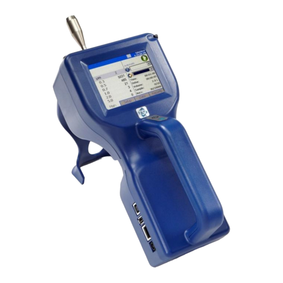
G e t t i n g H e l p To obtain assistance with this product or to submit suggestions, please contact Customer Service: TSI Incorporated 500 Cardigan Road Shoreview, MN 55126 U.S.A. Fax: (651) 490-3824 (USA) Fax: 001 651 490 3824 (International) - Page 13 C H A P T E R 1 I n t r o d u c t i o n a n d U n p a c k i n g ® The AeroTrak Model 9306 Airborne Particle Counter (particle counter) is a lightweight, handheld particle counter with a touch-screen interface.
- Page 14 ® U n p a c k i n g t h e A e r o T r a k H a n d h e l d A i r b o r n e P a r t i c l e C o u n t e r ®...
-
Page 15: Chapter 1 Introduction And Unpacking
Qty. Item Description Part/Model Reference Picture TrakPro™ Lite 7001901 Secure Software CD for 21 CFR Part 11 compliant data downloading (includes manuals) Operation Manual 6004215 Included on TrakPro™ Lite Secure Software CD Quick Start Guide 6004216 Calibration certificate Optional Accessories The following photos and table list optional accessories. - Page 16 Item Description Part/Model Reference Picture Temperature/humidity probe 700084 Stainless Steel Isokinetic 700004 inlet Isokinetic probe (used with 700001 AL tubing) 700002 SS 0.1 cfm Barb Inlet Fitting 700020 Tubing, Superthane 1/8-inch 700009 ID x ¼-inch OD, Clear 100 ft ® AeroTrak Handheld Airborne Particle Counter...
-
Page 17: Instrument Description
C H A P T E R 2 G e t t i n g S t a r t e d This chapter provides information to help you use the Model 9306 ® AeroTrak Handheld Airborne Particle Counter including: ... -
Page 18: Using The Instrument Stand And Stylus
U s i n g t h e I n s t r u m e n t S t a n d a n d S t y l u s The Model 9306 is equipped with an integral instrument support stand. To open the stand, grasp it by the large finger hole and pull it out until it locks into place. -
Page 19: Providing Power
P r o v i d i n g P o w e r The Model 9306 may be powered using a rechargeable lithium-ion battery, or through an AC power cord. NOTES: When using AC power, the battery (if installed) charges when the instrument is on, but not while actively sampling. -
Page 20: To Use Ac Power
To Use AC Power 1. Connect the AC power adapter to the power cord. 2. Insert the AC power adapter into the side of the Model 9306. 3. Connect the power cord to an outlet. 4. Press the on/off button (located on the front of the instrument handle). -
Page 21: Installing An Isokinetic Inlet
I n s t a l l i n g a n I s o k i n e t i c I n l e t The Isokinetic inlet smoothly accelerates air into the inlet of the instrument. To install, simply thread the inlet directly onto the inlet nozzle until finger tight. -
Page 22: Installing A Temperature/Relative Humidity Probe
I n s t a l l i n g a T e m p e r a t u r e / R e l a t i v e H u m i d i t y P r o b e To install the optional temperature/relative humidity probe: 1. -
Page 23: Screen Layout And Functionality
C H A P T E R 3 O p e r a t i o n ® The Model 9306 AeroTrak Handheld Airborne Particle Counter is controlled using a touch screen display. Use the plastic stylus or your finger tip. DO NOT use sharp objects (such as a pen point) that may damage the screen overlay. -
Page 24: Software Input Panel (Keyboard Or Keypad)
Software Input Panel (Keyboard or Keypad) 1. Throughout the setup screens, a keyboard or keypad appears on the screen when text or numbers may be entered. 2. When you enter information using the keyboard, press either the (Enter) or Esc keys when you are done. When you enter data using the keypad, the data is entered when you press OK on the screen. - Page 25 Icon Description Instrument status error. If this icon is shown, it can be pressed and a more detailed description of the operational error will be shown. Refer to the troubleshooting section for appropriate actions. Sufficient flow through the instrument. NOTE: During Start Delay (Delay) and Hold Times (Hold), this is only an indicator of flow On.
- Page 26 Field Description Displays the Zone where the sample is being taken by the instrument. Press the icon to display a (Zone) summary of information for the Zone. This dropdown box allows selection of a preconfigured Location to associate the sampled (Location) data to.
-
Page 27: Zoomed Data Screen
Zoomed Data Screen The Zoomed Data screen is entered by touching in the size and count part of the main tab display. The bottom portion of the screen summarizes the concentrations for the currently selected location. Tap the size and count portion of the display to switch back to the Main Tab display. -
Page 28: Setup Tab
Setup Tab The setup tab provides access to the following: Zones Setup Identify and save the location information associated with collected samples. Recipes Setup Save a group of settings (a Recipe) that you use over and over so you do not have to reset individual settings. -
Page 29: Zone Setup Screen
Zone Setup Screen ”Zones” are a convenient way to group sample data for printing and export, and are required for creating standards-based classification reports. A Zone contains 1 or more “Locations”; this is modeled after cleanroom standards that prescribe the classification of a zone (or room) by taking samples at various locations within the zone. - Page 30 To Delete A Zone To delete a zone from the configuration screen, select (highlight) the zone name and press Delete. A verification message “Are you sure you want to delete this Zone?” appears. Press Yes to delete the zone. A zone that has data associated with it cannot be deleted. The data associated with the zone must be deleted from the instrument before the zone can be deleted.
- Page 31 3. Enter names for each location in the zone and the press Add after entering each. The name will be added to the box on the left side of the screen. 4. Press the Recipe tab. The Recipe screen is displayed with a default recipe in the “Selected Recipe”...
- Page 32 4. The Locations screen displays the locations within the selected zone. You can add, rename, or remove a location from the zone. You can also move the location name up or down in the list. The Auto feature will generate the number of locations required by the chosen standard.
-
Page 33: Recipes Setup Screen
N o t e If you edit a recipe, the changes will affect all zones using that recipe. Be certain that is what you want to do. 7. When you have made all the changes, press Save. Recipes Setup Screen Use the Recipes Setup Screen to review recipes, add or delete recipes, and edit recipes. - Page 34 2. On the Recipe tab, enter a name or edit the name of the recipe. For a new recipe, a default name will appear, but you can type over it and name the recipe anything you want. 3. Select the Count Mode: options are Automatic, Manual, and Beep as described below.
- Page 35 5. Press the Timing tab to enter or edit start delay times, sample time, hold time, etc. 6. To make changes to the timing settings, highlight the component to change (hours, minutes, seconds, etc.) and use the on-screen keypad to change the value. W A R N I N G Instrument status alarms are inactive if samples times are 10 seconds or less.
- Page 36 Field Description Start Delay Start Delay indicates how long it will be before the first sample is taken. NOTE: It takes approximately 10 seconds for the pump to reach the flow set point; taking a measurement before the pump is functioning properly may result in a data and flow error.
- Page 37 To acknowledge the alarm and silence the buzzer, tap the alarm icon N o t e s In Differential modes (Δ), disabling one or more channels will disable all threshold alarms. Other alarms are not affected. While in beep mode, a threshold of 0 will not trigger an audible alarm even if Alarm is enabled.
-
Page 38: System Setup Screen
System Setup Screen Use the System Setup screen to select (or change) the power on password, set up a password, select system configuration parameters, select print settings, schedule printing and clear samples. ® 3-16 AeroTrak Handheld Airborne Particle Counter... -
Page 39: Change Power On Password Screen
Change Power On Password Screen If a Power On password has been previously set, that password must be entered before being allowed to change the Power On password. If a Power On password is set, then on instrument startup a password screen will ask for the password before the instrument can be used. -
Page 40: Change Setup Password Screen
Change Setup Password Screen If a Setup password has been previously set, that password must be entered before being allowed to change the Setup password. If a Setup password is set, clicking on the setup tab at the bottom of the main screen brings up a password screen. -
Page 41: Configuration Screen
Configuration Screen Use the Configuration screens to set configuration parameters. Press OK when finished. Field Description and on Zoom Select to zoom in on both cumulative (Σ) and differential (Δ) counts on the Main Tab. To zoom the Main Tab, select on the left side of the Main Tab. -
Page 42: Print Setup Screen
Print Setup Screen A hard copy of a sample set or statistics can be printed from the instrument using an optional thermal printer. Use this screen to set print parameters. Press OK when finished. Field Description Serial Number Indicates that the serial number of the particle counter used to collect the data will be printed. -
Page 43: Print Schedule Screen
Print Schedule Screen Use the Print Schedule screen to schedule automatic printing. Choose to either print when an alarm occurs or print whenever a sample is complete. “English Only Printing” can be selected to print reports in English even when the selected language is a language other than English. Prints default zones and locations in English. -
Page 44: Clear Samples Screen
Clear Samples Screen Use the Clear Samples screen to clear all samples from the internal database. Select Yes to clear all samples. Select No to return to the System Setup screen. C A U T I O N WHEN “YES” IS SELECTED ON THE CLEAR SAMPLES SCREEN, ALL SAMPLE RECORDS WILL BE DELETED FROM THE INSTRUMENT! THERE IS NO WAY TO RECOVER THEM ONCE THEY HAVE BEEN DELETED. -
Page 45: Date And Time Screen
Date and Time Screen Use the Date and Time screen to set the current date and time and set the date format. Press OK when finished. Select options using the arrows or tapping on the screen which brings up the keypad. Field Description Date... -
Page 46: Display Screen
Display Screen Use the Display screen to set or change visual parameters. Field Description Press this item to reset the screen alignment. Follow Screen Alignment the directions on the alignment screen. NOTE: The touchscreen display is aligned at the factory and typically will stay aligned for the life of the instrument. -
Page 47: Communication Screen
Communication Screen Use the Communication screen to configure the IP address, subnet, and default gateway to which the instrument belongs. Addresses can be entered using the arrows or by selecting a field and using the on-screen keypad. Field Description IP Address The numerical identification (logical address) that is assigned to this device when participating in a computer network utilizing the Internet Protocol for... -
Page 48: Regional Screen
Regional Screen Use the Regional screen to set the language in which the on-screen dialog is displayed and your regional format for numbers. Field Description Language Select the language in which you want on-screen dialog displayed; options are German, English, Spanish, French, Italian, Chinese, and Japanese. -
Page 49: Environment Screen
Environment Screen Use the Environment screen to set the units for temperature, which is displayed on the Main and Data Tabs, and the printouts when a humidity and temperature probe is hooked up to the instrument. Field Description Display temperature in degrees Fahrenheit. °... -
Page 50: Data Tab
Data Tab Use the Data tab to preview data that has been collected. To scroll though the records, use the elevator (slide) on the right. The record number is displayed at the bottom of the tab. As each record displays, its data and relevant parameters are displayed. - Page 51 Field Description Date Date on which the data was collected. Time Time at which data was collected. Temperature Temperature at the end of the time the data was collected (if probe connected during sampling). Humidity Humidity level at the end of the time the data was collected (if probe connected during sampling).
-
Page 52: Compliance
Export Data Screen Use the Export Data screen to export sample data to a flash drive. Select the name of the file and range of data to export. Data is downloaded into an XML file that can be opened with commonly used spreadsheet programs. - Page 53 2. Select a file from the list and click: a. “Export” to overwrite an existing file selected from the file list. b. “Export As…” to enter a file name. Then select OK. 3. Select Sample data by Zone or by Sample index range with option of limiting samples to a date range.
- Page 54 5. This form allows you to select data for export by range of sample Index. Tap Select Range radio button and then select the lower and upper sample index numbers. To select data for export by zone instead, tap the Select by Zone button at the bottom. (continued on next page) ®...
- Page 55 6. Once the records or the Zones have been selected, press Export… to begin exporting. Status screens allow viewing the progress of the export. C a u t i o n Do NOT remove the external drive during the export process. If the thumbdrive is removed, re-insert and restart the download process.
-
Page 56: Print Data
Print Data The print button allows a range of sample data to be printed using the optional printer. The “Print by Record” form or the “Print by Zone” form can be used. Both forms provide the option to limit data selection to a date range. - Page 57 1. Move a zone to the box on the right to select it for printing. To select data by range or sample index instead, tap the Select by Record button at the bottom. 2. The “Select by Record” screen above allows you to select data by range of sample index number.
-
Page 58: Reports Tab
Reports Tab Use the Reports Tab screen to select various standard reports for viewing and printing. Select a zone to be included in the report and you have the option to restrict data to a date range. Check the “Use Start Date”... - Page 59 C H A P T E R 4 D a t a H a n d l i n g U S B D a t a D o w n l o a d ® The Model 9306 AeroTrak Handheld Airborne Particle Counter is equipped with a USB A host drive that will allow for the downloading of stored data to a USB Thumb drive.
- Page 60 U S B C o m p u t e r C o m m u n i c a t i o n ® The Model 9306 AeroTrak Handheld Airborne Particle Counter is equipped with a USB compatible cable for uploading and downloading information to a PC.
-
Page 61: Chapter 5 Maintenance
C H A P T E R 5 M a i n t e n a n c e The chapter contains maintenance and troubleshooting solutions for the ® Model 9306 AeroTrak Handheld Airborne Particle Counter. N o t e There are no user-serviceable parts inside this instrument. - Page 62 (This page intentionally left blank) ® AeroTrak Handheld Airborne Particle Counter...
- Page 63 C H A P T E R 6 T r o u b l e s h o o t i n g Symptom Possible Cause Corrective Action Counts are too low. Instrument is being operated outside Operate instrument within temperature or relative humidity specifications.
- Page 64 Symptom Possible Cause Corrective Action Battery does not charge. The unit must be turned on but not in Turn on unit. sampling mode for the battery to charge. The battery will only charge if the unit is turned on but is not actively taking a sample.
-
Page 65: Chapter 7 Contacting Customer Service
C o n t a c t i n g C u s t o m e r S e r v i c e This chapter gives directions for contacting people at TSI Incorporated for technical information and directions for returning the Model 9306 ®... -
Page 66: Technical Support
TSI Instruments Ltd. Stirling Road Cressex Business Park High Wycombe, Bucks HP12 3ST UNITED KINGDOM Telephone: +44 (0) 149 4 459200 Fax: +44 (0) 149 4 459700 E-mail: tsiuk@tsi.com Technical Support TSI Instruments Singapore Pte Ltd 150 Kampong Ampat #05-05 KA Centre Singapore 368324 Telephone: +65 6595-6388... - Page 67 TSI France Inc. Hotel technologique BP 100 Technopôle de Château-Gombert 13382 Marseille cedex 13 FRANCE Telephone: + 33 (0) 491 11 87 64 Fax: + 33 (0) 491 11 87 65 E-mail: tsifrance@tsi.com ® R e t u r n i n g t h e A e r o T r a k H a n d h e l d A i r b o r n e P a r t i c l e C o u n t e r f o r S e r v i c e Visit our website at...
- Page 68 (This page intentionally left blank) ® AeroTrak Handheld Airborne Particle Counter...
- Page 69 A P P E N D I X A S p e c i f i c a t i o n s All specifications meet or exceed ISO 21501-4 and JIS B9921. They are subject to change without notice. Specification Description Size Range...
- Page 70 Specification Description Languages English, Spanish, German, French, Italian, Japanese, and Chinese (simplified) Reports Provides Pass/Fail on FS-209E, ISO 14644-1 and EU GMP Printer Optional external printer supported External Surface High impact injection molded plastic AC Power (power to AC 110 to 240 VAC 50 to 60 Hz Universal in-line power adapter) supply DC Power (power to...
- Page 71 C o m p l i a n c e CE Marking EN61326 / EN 55011, Class BA: Radiated Emissions EN61326 / EN 55011, Class BA: Conducted Emissions EN61000-3-2: Harmonics EN61000-3-3: Voltage Fluctuations EN61000-4-2: Electrostatic Discharge Immunity EN61000-4-3: Electromagnetic Field Immunity EN61000-4-4: Burst Immunity EN61000-4-6: Conducted PS Immunity EN61000-4-5: Surge Immunity...
- Page 72 (This page intentionally left blank) ® AeroTrak Handheld Airborne Particle Counter...
-
Page 73: Chapter 4 Data Handling
I n d e x clear samples screen, 3-22 date and time screen, 3-23 communication mode, A-1 DC power, A-2 24 hour, 3-23 communications default gateway, 3-25 default gateway, 3-25 delay, 3-4, 3-14 IP address, 3-25 delete zone, 3-8 subnet mask, 3-25 detector warning, 6-2 AC power, A-2 use dhcp, 3-25... - Page 74 recipes screen channels T tab, 3-14 help, x, 7-1 old password, 3-17, 3-18 recipe tab, 3-11 HEPA zero filter assembly, 1-2 on alarm, 3-21 timing tab, 3-13 hold, 3-14 on sample, 3-21 cycles, 3-14 humidity, 3-29 operating conditions, A-2 delay, 3-14 operation, 3-1 hold, 3-14 sample time, 3-14...
-
Page 75: Usb Computer Communication
setup tab (continued) system setup, 3-6 zero check, 5-1 zones setup, 3-6 maintenance, 5-1 size, 3-28 zero count level, A-1 size range, 1-1, A-1 zone, 3-4, 3-28 software zone icon, 3-3 installation, 4-2 zone setup specifications, A-1 add zone, 3-8 stainless steel isokinetic inlet, 1-4 air flow, 3-7 stand, 2-1... - Page 77 TSI Incorporated – Visit our website www.tsi.com for more information. Tel: +1 800 874 2811 India Tel: +91 80 67877200 Tel: +44 149 4 459200 China Tel: +86 10 8219 7688 France Tel: +33 4 91 11 87 64 Singapore...
Need help?
Do you have a question about the AEROTRAK 9306 and is the answer not in the manual?
Questions and answers