Table of Contents
Advertisement
Advertisement
Table of Contents

Related Manuals for Keysight N2791A


Summary of Contents for Keysight N2791A
- Page 1 N2791A 25 MHz and N2891A 70 MHz High-Voltage Differential Probes User’s Guide...
-
Page 2: Table Of Contents
Handling the Probe 3 N2791A/N2891A High-Voltage Differential Probes 4 Contents and Accessory Kits 5 Characteristics 7 Safety Information 9 Using the N2791A High-Voltage Differential Probe 10 Using the N2891A High-Voltage Differential Probe 11 N2791A Plots 12 N2891A Plots 16 Using the Accessories 20... -
Page 3: Inspecting The Probe
Office. • If the shipping container is damaged, or the cushioning materials show signs of stress, notify the carrier as well as your Keysight Technologies Sales Office. Keep the shipping materials for the carrier’s inspection. The Keysight Technologies office will arrange for repair or replacement at Keysight Technologies’... -
Page 4: N2791A/N2891A High-Voltage Differential Probes
(up to 700 V of differential or common mode voltage for the N2791A and up to 7000 V of differential or common mode voltage for the N2891A). The N2791A offers user-... -
Page 5: Contents And Accessory Kits
Contents and Accessory Kits Contents and Accessory Kits The following table lists the parts included with the N2791A high-voltage differential probe. Part Quantity N2791A 25 MHz differential probe Safety Hook, Red Safety Hook, Black Alligator Clip, Red Alligator Clip, Black... - Page 6 Contents and Accessory Kits The following table lists the parts included with the N2891A high-voltage differential probe. Part Quantity N2891A 70 MHz differential probe Safety Hook, Red Safety Hook, Black High Voltage Alligator Clip, Red High Voltage Alligator Clip, Black USB Power Cord (2 m) AA Battery Trimmer Tool...
-
Page 7: Characteristics
Characteristics Characteristics Characteristics for the N2791A and N2891A high-voltage differential probes are shown below. The probe / oscilloscope should be warmed up for at least 20 minutes before any testing and the environmental conditions should not exceed the probe’s specified limits. - Page 8 202 mm x 83 mm x 38 mm (8.0 inches x (6.7 inches x 2.5 inches x 0.83 inches) 3.3 inches x 1.5 inches) Environmental Specifications (same for both N2791A and N2891A) Temperature Operating: -10 °C to +40 °C Nonoperating: -30 °C to +70 °C...
-
Page 9: Safety Information
Observe Maximum Working Voltage To avoid injury, do not use the N2791A probe above 1000 Vrms CAT II (both 10:1 and 100:1 attenuation settings) between each input lead and earth or between the two input leads. Do not use the N2891A probe above 5000 Vrms CAT I (1000:1 attenuation) or 500 Vrms CAT I (100:1 attenuation) between the two input leads. -
Page 10: Using The N2791A High-Voltage Differential Probe
Using the N2791A High-Voltage Differential Probe Use Proper Power Source To ensure this probe functions well, use four AA batteries or the supplied USB power cord. For Indoor Use Only Only use this probe indoors. Do Not Operate With Suspected Failures If you suspect there is damage to this probe, have it inspected by a qualified service personnel. -
Page 11: Using The N2891A High-Voltage Differential Probe
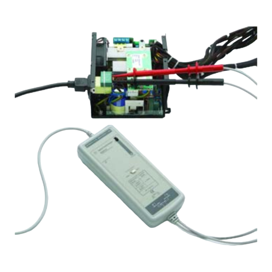
Using the N2891A High-Voltage Differential Probe Using the appropriate probe accessories, connect the inputs to the circuit under test. To protect against electrical shock, use only the accessories supplied with this probe or in the accessory kit. This probe is to carry out differential measurements between two points on the circuit under test. -
Page 12: N2791A Plots
N2791A Plots N2791A Plots Step Input Signal Measured Step Response (17 ns 10-90% rise time) -0.2 -100 Time (ns) Graph of normalized step response (50Ω, 16.5 ns rising edge step generator), 17 ns normalized rising edge (10-90%), 10:1 attenuation Measured Step... - Page 13 N2791A Plots Vout/Vin Vout Frequency (MH z) Graph of dB(Vin), dB(Vout) + 20dB, and dB(Vout/Vin) + 20dB frequency response, 10:1 attenuation Vout/Vin -2.5 Vout -7.5 Frequency (MH z) Graph of dB(Vin), dB(Vout) + 40dB, and dB(Vout/Vin) + 40dB frequency response,...
- Page 14 N2791A Plots -100 Frequency (H z) Graph of dB(Vout/Vin) + 20dB frequency response when inputs driven in common mode (common mode rejection), 10:1 attenuation Ω 22 pF Frequency (H z) Magnitude plot of probe input impedance versus frequency (single-ended mode)
- Page 15 N2791A Plots 1100 V rm s Frequency (H z) Typical derating plot of the absolute maximum input voltage in common mode...
-
Page 16: N2891A Plots
N2891A Plots N2891A Plots Step Input Signal Probe Step Response (10 ns 10-90% rise time) -0.2 Time (nS) Graph of normalized step response (50 W, 10 ns rising edge step generator), 10 ns normalized rising edge (10-90%), 100:1 attenuation Step Input Signal Probe Step Response (10 ns 10-90% rise time) -0.2... - Page 17 N2891A Plots Frequency Hz Graph of dB (S21) + 40 dB frequency response, 100:1 attenuation Frequency Hz Graph of dB (S21) + 60 dB frequency response, 1000:1 attenuation...
- Page 18 N2891A Plots Frequency (Hz) Graph of dB (S21) + 40 dB frequency response when inputs driven in common mode (common mode rejection), 100:1 attenuation differential 5 pF single-ended 7.2 pF Frequency (Hz) Magnitude plot of probe input impedance versus frequency, single-ended and differential...
- Page 19 N2891A Plots Vrms Frequency (Hz) Typical derating plot of the absolute maximum input voltage in common mode Input impedance equivalent circuit diagram...
-
Page 20: Using The Accessories
Using the Accessories Using the Accessories The accessories supplied with the N2791A and N2891A probes are attached by pushing them onto the probe leads as shown below. hook or clip probe lead The following accessories are supplied with the N2791A probe and with the N2791-68700 Accessory Kit. -
Page 21: N2791A Performance Verification Procedures
6 Disable the Fluke calibrator output, disconnect the channel 1 active head from channel 1 of the oscilloscope. 7 Connect the output of the N2791A probe to channel 1 of the oscilloscope. 8 Attach the BNC adapter to the Fluke channel 1 active head. - Page 22 N2791A Performance Verification Procedures 9 Attach the differential probe input leads by clipping the alligator clamp to the BNC adapter banana post. 10 Set the probe to 100:1. Set the Fluke calibrator to 10 V and 1 KHz standard amplitude output (channel 1, square wave, 1 MΩ load).
-
Page 23: N2791A Performance Verification Test Record
N2791A Performance Verification Test Record N2791A Performance Verification Test Record Keysight Technologies N2791A 25 MHz Differential Probe Serial No.:________________________ Certification Date:________________ Tested By:_______________________ Recommended Test Interval: 1 Year _________________________________ Recommended Date of Next Certification:_________ _________________________________ Certification Temperature:_____________________ Test Probe Settings... -
Page 24: N2891A Performance Verification Procedures
BNC Adapter BNC (f) to Dual Banana (m) Keysight 1251-2277 Interconnection Adapter between probe and generator 50 Ω BNC Feed Through 50 Ω precision feed through Keysight 11048C Termination Adapter between probe and calibrator for bandwidth verification DC Differential Gain Accuracy WARNING: Generator produces hazardous voltages. - Page 25 N2891A Performance Verification Procedures 2 Set the volts/division on channel 2 of the oscilloscope to 500 mV/div. Trigger on channel 2, select 50 Ω impedance. 3 Set the calibrator 9500B’s channel 2 as the trigger channel (50 Ω load). Connect the calibrator’s channel 2 active head to channel 2 of the oscilloscope.
-
Page 26: N2891A Performance Verification Test Record
N2891A Performance Verification Test Record N2891A Performance Verification Test Record Keysight Technologies N2891A 70 MHz Differential Probe Serial No.:_______________________ Certification Date:________________ Tested By:_______________________ Recommended Test Interval: 1 Year _________________________________ Recommended Date of Next Certification:_________ _________________________________ Certification Temperature:_____________________ Test Probe Settings... -
Page 27: Trimmer Tool
Follow this procedure to perform the offset zero calibration. 1 Connect the N2791A/N2891A probe to channel 1 of the scope. Turn on the probe power. You may use the USB power code or batteries to power the probe. Select the probe attenuation ratio to 10:1 (for N2791A) or 100:1 (for N2891A). - Page 28 Offset Zero Calibration Procedure...
- Page 29 Operation of any electrical instrument in such an environ- ment constitutes a definite safety hazard. • Do not use the instrument in a manner not specified by the manufacturer. Keysight Technologies 1900 Garden of the Gods Road Colorado Springs, CO 80901...
- Page 30 Notices ity and fitness for a particu- WARNING lar purpose. Keysight shall not be liable for errors or for A WARNING notice incidental or consequential denotes a hazard. It calls © Keysight Technologies, Inc. damages in connection with 2009-2014 attention to an operating...
- Page 32 Keysight Technologies, Printed in the Philippines August 2014 Manual Part Number: N2791-97003 *N2791-97003*...
Need help?
Do you have a question about the N2791A and is the answer not in the manual?
Questions and answers