
Related Manuals for Philips LTC 9405 Series


Summary of Contents for Philips LTC 9405 Series
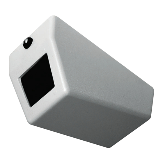
- Page 1 LTC 9405 Series Wall/Ceiling Security Housings Philips Communication & Security Systems...
-
Page 2: Important Safeguards
IMPORTANT SAFEGUARDS 1. Read Instructions - All the safety and operating instructions should be read before the unit is operated. 2. Retain Instructions - The safety and operating instructions should be retained for future reference. 3. Heed Warnings - All warnings on the unit and in the operating instructions should be adhered to. -
Page 3: Safety Precautions
SAFETY PRECAUTIONS CAUTION: TO REDUCE THE RISK OF ELECTRICAL SHOCK, DO NOT OPEN COVERS. NO USER SERVICEABLE PARTS INSIDE. REFER SERVICING TO QUALIFIED SERVICE PERSONNEL. This label may appear on the bottom of the unit due to space limitations. The lightning flash with an arrowhead symbol, within an equilateral triangle, is intended to alert the user to the presence of un-insulated "dangerous voltage"... -
Page 5: Care And Maintenance
These housings are ideal for any application requiring secure CCTV monitoring. LTC 9405 has an overall size of 279 mm x 165 mm x 140 mm (11 in x 6.5 in x 5.5 in). The LTC 9405 series housings accept camera-lens combinations up to 190 L x 68 W x 68 H mm (7.5... - Page 6 3. For all models, unscrew the screw or the lock until the front of the cover is free from the top panel. 4. With the unit on a workbench or table, hold the cover stationary. Remove the top panel by grasping it and pulling it rearward, then upward for about 51 mm (2 in ), and finally rearward again until the slots in the top panel have cleared the studs in the cover.
- Page 7 Figure 6: Installing the Mount System Figure 7: Securing the Mount System with Alternate Bracket 3. Secure the camera to the mount using the ¼-20 x ½ inch button-head flange screw provided in the hardware kit. See figures 8, 9 and 10. Figure 8: Camera Mounts Figure 9: Camera and Mount System Figure 10: Camera Mounted with Alternate Bracket to a...
- Page 8 2. Inspect the alignment of the camera / lens in the unit. The camera / lens should be placed as close to the viewing window as possible. Remove the cover and make adjustments as needed and then replace the cover. 3.
- Page 9 SECURITE DANGER: POUR ÉVITER TOUT RISQUE D'ÉLECTROCUTION, NE PAS OUVRIR LE BOÎTIER. IL N'Y A PAS DE PIÈCES REMPLAÇABLES À L'INTÉRIEUR. POUR TOUTE RÉVISION, S'ADRESSER À UN TECHNICIEN SPÉCIALISÉ. En raison de limitation de place, cette étiquette peut être placée sur le dessous de l'appareil.
-
Page 11: Entretien Et Maintenance
DESCRIPTION Les boîtiers de protection LTC 9405 pour montage mural ou sur plafond ont été notamment conçus pour assurer la surveillance des prisons, des parkings ou des garages et des hôpitaux. - Page 12 Panneau supérieur Vis anti-effraction ou verrou Figure 1 : Retrait du capot 3. Quel que soit le modèle, retirez la vis ou ouvrez le verrou afin de dégager le panneau avant du capot du panneau supérieur. 4. Placez l'unité sur un plan de travail ou une table et immobilisez le capot.
- Page 13 Installation du bloc caméra/objectif 1. Si dans le cadre d'une installation murale la caméra doit être montée horizontalement, retirez le support de fixation de la caméra du support de montage, puis installez l'applique de fixation amovible de la caméra fournie dans le kit matériel. Veuillez vous référer à...
- Page 14 Caméra Figure 10 : Montage mural d'une caméra fixée sur un support amovible Montage final 1. Remettez le capot en place en alignant les deux pitons situés à l'arrière du capot avec les ouvertures des supports de fixation en forme de Z situés sur le panneau supérieur. Faites glisser le capot vers l'arrière, puis vers le haut et enfin vers l'arrière.
- Page 15 SICHERHEITSVORKEHRUNGEN VORSICHT: UM EINEN ELEKTRISCHEN SCHLAG ZU VERMEIDEN, ABDECKUNG NICHT ENTFERNEN. WARTUNGEN ALLER ART QUALIFIZIERTEM PERSONAL ÜBERLASSEN. Aus Platzgründen kann diese Warnung auf der Unterseite des Gerätes angebracht sein. Das Blitzsymbol im gleichseitigen Dreieck soll den Benutzer auf nicht isolierte "Hochspannung" im Gehäuse aufmerksam machen, die eventuell stark genug ist, um einen elektrischen Schlag zu verursachen.
- Page 17 Gehäuse sind ideal für alle Anwendungen, die eine sichere Video-Überwachung verlangen. LTC 9405 hat eine Größe von 279 mm x 165 mm x 140 mm). Die Gehäuseserie LTC 9405 ermöglicht die Kombination von Kameralinsen von bis zu to 190 x 68 x 68 mm (L x W x H).
- Page 18 Befestigungsplatte vor unbefugtem Verstellen gesicherte Schraube oder Schloß Abb. 1: Entfernen der Abdeckung 3. Gilt für alle Modelle: Lösen Sie die Schraube bzw. Verriegelung, so daß sich die Vorderseite der Abdeckung von der Befestigungsplatte löst. 4. Legen Sie das Gerät auf eine flache, standfeste Werkbank oder einen Tisch.
- Page 19 Installation der Kamera/Linse 1. Falls es erforderlich ist, die Kamera horizontal an der Wand zu installieren, müssen die Kameraschienen der Installationsvorrichtung entfernt und gegen die im Zubehörset befindliche Kameraschiene ausgetauscht werden. Siehe Abbildung 5. Montageschiene Schraube Kameraschiene Abbildung 5: Von vertikaler Kamerainstallation auf horizontale Installation wechseln 2.
- Page 20 Kamera Abbildung 10: Kamera mit Wechselschiene an der Wand montiert Endmontage 1. Bringen Sie die Abdeckung an. Dabei richten Sie die beiden Bolzen an der Rückseite der Abdeckung so aus, daß sie in die z-förmigen Schlitze in der Befestigungsplatte eingreifen können.
- Page 21 PRECAUCIONES DE SEGURIDAD PRECAUCION: PARA REDUCIR EL RIESGO DE CHOQUE ELÉCTRICO, FAVOR NO ABRIR LA CUBIERTA. ESTE EQUIPO NO CONSTA DE PIEZAS O PARTES QUE REQUIEREN SERVICIO O MANTENIMIENTO. PARA REPARACIONES FAVOR REFERIRSE A UN TÉCNICO CALIFICADO. Debido a limitaciones de espacio, esta etiqueta puede aparecer en la parte inferior de la unidad.
- Page 23 Estas carcasas resultan idóneas para cualquier aplicación que necesite una supervisión segura de TVCC. LTC 9405 tiene un tamaño total de 279 mm x 165 mm x 140 mm (11 pulg x 6,5 pulg x 5,5 pulg). Las carcasas Serie LTC 9405 aceptan combinaciones de lentes de cámara de hasta...
- Page 24 Panel superior Tornillo blindado o cerradura con llave Figura 1: Extracción de la tapa 3. Para todos los modelos, desatornille el tornillo o la cerradura hasta que la tapa se libere del panel superior. 4. Con la unidad sobre un banco de trabajo o una mesa, mantenga la tapa fija.
- Page 25 Instalación de cámara/lente 1. Si la instalación necesita que la cámara esté montada horizontalmente en la pared, extraiga el soporte de la cámara del sistema de montaje e instale el soporte de cámara alternativo suministrado en el juego de hardware. Véase la figura 5.
- Page 26 Cámara Figura 10: Cámara montada en una pared con el soporte alternativo Montaje final 1. Monte la tapa alineando los dos pasadores cercanos a la parte posterior de la tapa con las aberturas de las ranuras con forma de z del panel superior. Deslice la tapa hacia atrás y hacia arriba y, por último, hacia atrás de nuevo.
- Page 27 VEILIGHEIDSVOORZORGEN VOORZICHTIG RISICO VAN ELEKTRISCHE SCHOK NIET OPENEN LET OP: OPEN DE BEHUIZING NIET OM HET RISICO OP EEN ELECTRISCHE SCHOK TE VOORKOMEN. HET APPARAAT BEVAT GEEN VERVANGBARE ONDERDELEN. LAAT ONDERHOUD OVER AAN GEKWALIFICEERD PERSONEEL. Dit label kan wegens ruimtegebrek op de onderkant van het apparaat zitten.
- Page 29 10 mm. Demonteren 1. Haal de eenheid uit de verpakking. 2. Voor de modellen LTC 9405/00 en 9405/03 is een speciaal gereedschap nodig om de beveiligingsschroef in het frontpaneel los te draaien. Zie afbeelding 1. Bij de modellen LTC 9405/01 en 9405/05 is de speciale sleutel nodig om het slot op het voorpaneel te openen.
- Page 30 Bovenpaneel Beveiligings-schroef of slot voor sleutel Afbeelding 1: Behuizing openen 3. Draai het schroefje los of open het slot tot de voorzijde loskomt van het bovenpaneel van de behuizing. 4. Leg de eenheid op een werkbank of tafel en houd de behuizing in een stabiele positie.
- Page 31 Camera/lens monteren 1. Als u de camera horizontaal aan een wand wilt monteren, maak de camera dan los van de montagebeugel en monteer de andere camerabeugel die als onderdeel van de kit is geleverd. Zie afbeelding 5. Bevestigings- beugel Schroef Camerabeugel Afbeelding 5: Andere camerabeugel monteren 2.
- Page 32 Camera Afbeelding 10: Camera met alternatieve beugel bevestigd aan een wand Montage afronden 1. Monteer de behuizing door de twee steunen bij de achterzijde van de kap uit te lijnen op de openingen van de Z-vormige uitsparingen in het bovenpaneel. Schuif het paneel naar achter, dan iets naar boven en dan weer naar achter.
- Page 33 NORME CAUTELATIVE DI SICUREZZA AVVERTENZA RISCHIO DI FOLGORAZIONE NON APRIRE! ATTENZIONE: PER RIDURRE IL RISCHIO DI SCOSSE ELETTRICHE, NON APRIRE I COPERCHI. ALL’INTERNO NON VI SONO COMPONENTI SU CUI L’UTENTE DEVE ESEGUIRE INTERVENTI DI MANUTENZIONE. AFFIDARE LA MANUTENZIONE A PERSONALE QUALIFICATO. A causa di limitazioni di spazio questa etichetta può...
- Page 35 CCTV di sicurezza. L'LTC 9405 ha dimensioni globali di 279 mm x 165 mm x 140 mm. Questi alloggiamenti sono in grado di alloggiare combinazioni telecamera-ottica con dimensioni fino a 190 P x 68 L x 68 A mm.
- Page 36 Pannello superiore Vite antiscasso o serratura a chiave Figura 1: Rimozione del coperchio 3. Per tutti i modelli, svitare la vite od aprire la serratura per sganciare il coperchio dal pannello frontale. 4. Collocando l'unità su un piano di lavoro o su un tavolo, tenere fermo il coperchio.
- Page 37 Installazione di telecamera/ottica 1. Se l'installazione richiede che la telecamera venga montata in orizzontale sulla parete, rimuovere la staffa porta telecamera dal sistema di fissaggio ed installare la staffa alternativa fornita con il kit ferramenta. Vedi figura 5. Staffa di montaggio Vite Staffa telecamera...
- Page 38 Telecamera Figura 10: Telecamera installata a parete con staffa alternativa Montaggio finale Montare il coperchio allineando i due perni in prossimità del retro del coperchio con le aperture delle fessure a forma di z del pannello superiore. Far scorrere il coperchio perso il retro dell'unità, poi verso l'alto ed infine nuovamente verso il retro.
- Page 40 3935 890 21181 99-40 © 1999 by Philips Electronics N.V. © 1999 by Philips Communication & Security Systems Inc. All Rights Reserved. Philips® is a registered trademark of Philips Electronics N. A. Corp. Data subject to change without notice...