Table of Contents
Advertisement
Advertisement
Table of Contents

Related Manuals for Megger TDR1000/3


Summary of Contents for Megger TDR1000/3
- Page 1 TDR1000/3 TDR1000/3P CFL510G TDR500/3 Time Domain Reflectometers User Manual...
-
Page 2: Table Of Contents
Controls Waste electrical and electronic equipment Rotary switch Test Lead selection Range and cursor control Repair and warranty Backlight and hold Megger contact information Setup Operation General testing procedure Operating modes Connection to cable under test Velocity factor Pulse widths... - Page 3 ■ ■ made. ■ ■ Use the correct lead set. On power systems the Megger fused lead set must be used. Refer to the Test Lead selection page in ■ ■ this user guide to identify the correct lead set.
- Page 4 Symbols The following symbols are used on this instrument CAUTION: RISK OF DANGER EQUIPMENT PROTECTED THROUGHOUT BY DOUBLE INSULATION OR REINFORCED INSULATION EQUIPMENT COMPLIES WITH RELEVANT EU DIRECTIVES EQUIPMENT COMPLIES WITH AUSTRALIAN EMC REQUIREMENTS (C-tick) (NOT FOR SAFETY) THIS EQUIPMENT SHOULD BE RECYCLED AS ELECTRONIC WASTE...
-
Page 5: Introduction
Introduction Thank you for purchasing this cable fault locator. Before attempting use of your new instrument please take the time to read this user guide, ultimately this will save you time, advise you of any precautions you need to take and could prevent damage to yourself and the instrument. This is an advanced instrument capable of identifying a wide range of cable faults. - Page 6 The instrument can be used on any cable consisting of at least two separate conductive elements, one of which may be the armouring or screen of the cable. It has internal matching networks to allow testing of 25 Ω, 50 Ω, 75 Ω and 100 Ω cables. (These typically correspond to power, coaxial data and data/telecoms cable).
-
Page 7: Overview
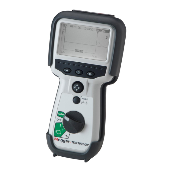
Overview Instrument Layout and Display Left & Right Arrows used in setup Backlit 256 x 128 Backlight dot matrix display Four Way Joy Switch Mainly controls range and cursor There is an audible tone on key Hold key presses. A low tone means the key is invalid Rotary Switch Turn to OFF to switch the instrument off. - Page 8 Display Battery State Indication Velocity Factor Impedance Range Cursor 2 Cursor 1 Hold Indicator Cursor 1 Cursor 2 Position Position Distance Between Cursor 1 and 2...
-
Page 9: Controls
Controls Rotary Switch Turn the switch from OFF to another position to turn the instrument on. The instrument may be turned off, by switching to OFF, or the instrument may switch itself off if it has not been used for 5 minutes or the battery is exhausted. The other selections are: Auto *Cursor 2... -
Page 10: Range And Cursor Control
Range & Cursor Control The range is set using the four way switch; press up to increase the Moving the four-way switch left or right will move the active cursor. range and down to reduce the range. -
Page 11: Backlight And Hold
Backlight and Hold Hold key. When the rotary switch is set to cursor 1, cursor 2, or Backlight key. Press the backlight key to switch the backlight on. It Auto, pressing the hold key will place an image of the current trace will switch off after one minute with no key press when activated, in grey on the display. -
Page 12: Setup
Setup The setup position allows the Velocity Factor, Impedance, Pulse Width, Gain, Distance Units, Sound and Display Contrast to be set. These are remembered when the instrument is switched off and recalled when switched back on. To adjust any of these parameters turn the rotary switch to the setup position. The parameter to be adjusted is highlighted at the top of the screen. -
Page 13: Operation
Operation General Testing procedure Ensure the correct test leads are firmly fitted into the sockets of the instrument. Switch on the instrument. The instrument will display the start screen for a couple of seconds, followed by a trace. The instrument will remember the settings last used. -
Page 14: Connection To Cable Under Test
Connection to Cable Under Test Connect the test lead to the cable under test. Connection may be made to a live power system with a voltage to earth (ground) less than 150 V with an installation (over voltage) category of I V or lower. This means that the instrument may be connected to any to primary supply circuits such as overhead cables. - Page 15 The 4mm plug to BNC adapter accessory is for use on cable distribution systems and low voltage cables only. The operator must verify that the circuit is safe for testing and take the appropriate precautions. In the event of no reflections being visible, increase gain in setup mode until any reflection can be easily identified. (If no reflections can be seen, try shorting or earthing the far end of the cable to ensure that you are “seeing”...
-
Page 16: Velocity Factor
Velocity Factor The velocity factor is used by the instrument to convert the measured time for a pulse to be reflected, into a distance. It is displayed as a ratio of the speed of light (eg 0.66 = 66% of the speed of light). If the exact length of cable is known and the reflection from the cable end is visible then an accurate velocity factor can be determined: Locate the reflection caused by the end of the known length of cable with the instrument set on the shortest possible range ■... -
Page 17: Pulse Widths
Pulse Widths As the range of the TDR is adjusted so the duration of the transmitted pulse changes. The pulse width range varies from 2 ns to overcome signal attenuation and enable the instrument to see further down a length of cable. The greater the range selected on the TDR, the wider the transmitted pulse. -
Page 18: Techniques
Other than replacing the batteries, the instrument has no user serviceable parts. In case of failure it should be returned to your supplier or an approved Megger repair agent. Cleaning the instrument should only be done by wiping with a clean cloth dampened with soapy water or Isopropyl Alcohol (IPA). -
Page 19: Battery
Battery Battery Replacement Switch off the instrument ■ ■ 1 - Disconnect leads Disconnect the instrument from any electrical circuits ■ ■ Undo two screws ■ ■ Remove the battery cover from the base. ■ ■ For battery replacement: ■ ■ 2 - Undo screws x 2 Remove old batteries Refit new batteries following correct... -
Page 20: Battery Indicator
Battery type: 5 x 1.5 V Alkaline LR6 (AA) or NiMH HR6 rechargeable. The crossed out wheeled bin placed on the batteries is a reminder not to dispose of them with general waste at the end of their life. Alkaline and NiMH batteries are classified as portable batteries and must be disposed of in accordance with local regulations. For details contact your local distributor. -
Page 21: Specifications
Specifications Except where otherwise stated, this specification applies at an ambient temperature of 20 ºC General Ranges: 10 m 25 m 100 m 250 m 1000 m 2500 m 5000 m 30 ft 75 ft 300 ft 750 ft 3000 ft 7500 ft 15000 ft Accuracy: ±1% of range ±... - Page 22 Mechanical: The instrument is designed for use indoors or outdoors and is rated to IP54. Case dimensions: 230 mm (9 in.) x 115 mm (4.5 in.) x 48 mm (2 in.) Instrument weight: 0.6 kg (1.32 lbs) Case material: Connectors: 19 mm Spaced.
-
Page 23: Waste Electrical And Electronic Equipment
Waste electrical and electronic equipment WEEE The crossed out wheeled bin placed on Megger products is a reminder not to dispose of the product at the end of its life with general waste. Megger is registered in the UK as a producer of electrical and electronic equipment. The Registration Number is WEE/HE0146QT. -
Page 24: Ordering Information
Ordering Information Item Order No. TDR1000/3 Time Domain Reflectometer includes Miniature clip test lead set 1001-788 TDR1000/3P Time Domain Reflectometer includes retractable sheath fused test lead set 1001-789 CFL510G Time Domain Reflectometer includes Bed of Nails test lead set and BNC adapter... -
Page 25: Test Lead Selection
Test Lead selection Split conductor Fused test lead set (1 pair) Megger Part Number 1002-015 Retractable sheath fused test lead (1 pair) Megger Part Number 1006-511 must be used on power systems Other test leads and the BNC adapter must only be used on low voltage systems... -
Page 26: Repair And Warranty
Fax: +44 (0) 1304 207 342 Megger operate fully traceable calibration and repair facilities, ensuring your instrument continues to provide the high standard of performance and workmanship you expect. These facilities are complemented by a worldwide network of approved repair and calibration... - Page 27 Approved Service Centres A list of Approved Service Centres may be obtained from the UK address above, or from Megger’s website at www.megger.com Returning your product to Megger - UK and USA service centres 1. When an instrument requires calibration, or in the event of a repair being necessary, a Returns Authorisation (RA) number must first be obtained from one of the addresses shown on the following page.
-
Page 28: Megger Contact Information
TEL: +1 (214) 330-3203 (INTERNATIONAL) FAX: +61 (0)2 9397 5911 FAX: +1 (214) 337-3038 THIS INSTRUMENT IS MANUFACTURED IN THE UNITED KINGDOM. THE COMPANY RESERVES THE RIGHT TO CHANGE THE SPECIFICATION OR DESIGN WITHOUT PRIOR NOTICE. MEGGER IS A REGISTERED TRADEMARK. TDR1000_3_EN_UG_V05 WWW.MEGGER.COM...
Need help?
Do you have a question about the TDR1000/3 and is the answer not in the manual?
Questions and answers