
Related Manuals for Fisher & Paykel WH8560J1


Summary of Contents for Fisher & Paykel WH8560J1
- Page 1 Service Manual Front Load Washer Models: WH8560P1 WH8560J1 WH8060P1 WH7560P1 WH7560J1 479646...
- Page 2 The latest version is indicated by the reprint date and replaces any earlier editions PRODUCT Brand Product Code Model Fisher & Paykel 92141 WH8560P1 FP AA 92142 WH8560J1 FP AA 92136 WH7560P1 FP AA 92137 WH7560J1 FP AA 93161 WH8060P1 FP AA 95141 WH8560P1 FP SG...
-
Page 3: Table Of Contents
479646 CONTENTS HEALTH & SAFETY ..........................5 SPECIFICATIONS ........................... 6 Product Dimensions ..........................6 Product weight ............................ 6 Water Rating ............................6 Energy Rating ............................. 7 Noise Rating ............................7 Heating Element ..........................7 Temperature Sensor ........................... 7 Detergent/Softener Dispenser ......................7 Wash Motor ............................ - Page 4 479646 WIRING DIAGRAM & COMPONENT RESISTANCES .................27 CONNECTOR LAYOUT .........................28 MODEL/SIZE SETTING .........................29 DIAGNOSTIC MODE ..........................30 11.1 Self Test ............................30 11.2 Water Valve Tests ..........................31 11.3 Drum Rotation Test .......................... 31 11.4 Door Lock Test ..........................31 11.5 Heater Test ............................31 SHOW ROOM MODE ..........................32 FAULT CODES ............................33 13.1 Fault Code Flow Charts ........................
-
Page 5: Health & Safety
479646 HEALTH & SAFETY When servicing the washer, health & safety issues must be considered at all times. Specific safety issues are listed below with the appropriate icon. Electrical Safety Ensure the mains power has been disconnected before servicing the washer. If the mains supply is required to be on to service the washer, make sure it is turned off when removing any electrical component or connection to avoid electric shock. -
Page 6: Specifications
479646 SPECIFICATIONS Product Dimensions Model Width Depth Height WH8560 600mm 650mm 850mm WH8060 600mm 650mm 850mm WH7560 600mm 590mm 850mm Product weight Model WH8560 WH8060 WH7560 Water Rating 4.5 Star Water rating using the Cotton 40 C cycle. -
Page 7: Energy Rating
479646 Energy Rating 220V - 240V AC, 50Hz, 2000W, 10Amp maximum 4 Star rating Noise Rating 72 dB Heating Element 1800 Watts. Resistance 30Ω. Overheat protection thermal link 167 Temperature Sensor NTC type: Reduces in resistance as temperature rises. Resistance 13K Ω @ 25 Detergent/Softener Dispenser Compartments: There are three: Prewash, Main Wash and Softener Pre Wash and Main wash are for powder detergent only DO NOT USE LIQUIDS. -
Page 8: Water Inlet Valves
479646 2.10 Water Inlet Valves Cold Valve dual type. Hot valve single type. 220V – 240V AC 50Hz. Resistance 4 KΩ +/- 5%. Cold maximum inlet temperature 35 Hot maximum inlet temperature 65 2.11 Pressure Sensor The machine is fitted with a pressure sensor, which controls the fill to any water level. The pressure sensor is a stand alone component which is replaceable and is connected to the tub air chamber via the pressure tube. -
Page 9: Product Finish
479646 2.17 Product Finish Cabinet - sheet metal powder coated. Inner drum - stainless steel. Outer tub – plastic. Outer door frame – plastic. Inner door – glass. Front panel – plastic. Kick panel – plastic. ... -
Page 10: Serial Label
479646 SERIAL LABEL The serial label is located on the front panel top centre of the door porthole. The last 9 digits of serial number indicate where manufactured, date of manufacture and sequential number. CR D 0001 CR= Manufacture code 0959= Product number D= Year 2013 G= 16... -
Page 11: Installation
479646 INSTALLATION... -
Page 12: Water Connection
479646 Water Connection Hot & cold inlet valves. 30 kPa (4.3PSI) Minimum water pressure. 1000 kPa (145PSI) Maximum water pressure. Levelling 50mm Adjustment height Level within – 2 degrees side to side & front to back. Drain Hose 1.2M Length of standard hose 2.5M Max length if extended 1200mm Max pump from floor 800mm Minimum... -
Page 13: Operation
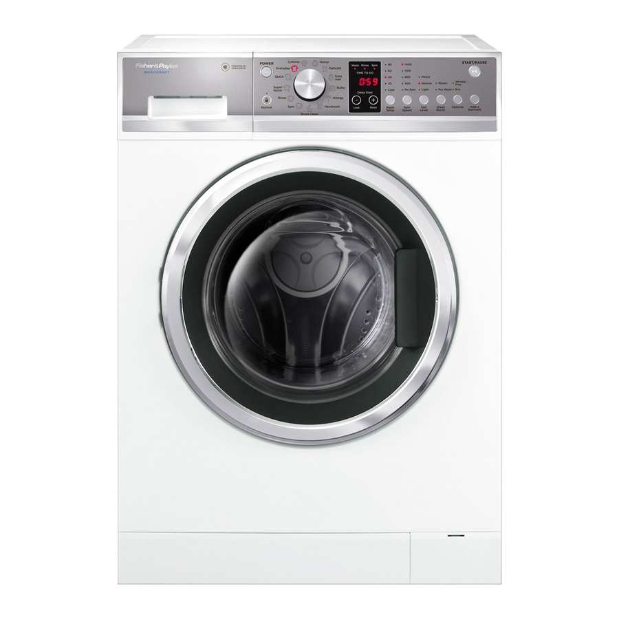
479646 OPERATION Control Panel Layout WH85/7560P1 (WashSmart) WH8060P1 WH8560J1/WH75J1 (QuickSmart) Power Button Used to switch washer on and off. Key Lock Activated and deactivated by pressing the KEY LOCK button for 2 seconds. Once activated, the light above the button is illuminated. -
Page 14: Power Off Memory Function
479646 Options Press this button to select the ECO and Wrinkle free functions. Wrinkle free (P models only) is for loads that are not going to be removed after the completion of the wash cycle and will tumble the clothes every 15 minutes for up to 12 hours. The ECO function saves energy and water. -
Page 15: Wash Programs
479646 WASH PROGRAMS Wash Program Chart WASHSMART Max. Default Load Cycle Designed for Default Setting Cycle size Time (Kg)* Normally Soiled 1400 rpm 7.5 , 8.0 Cottons** 2:17 everyday cotton loads or 8.5 Normally or lightly 1400 rpm 7.5, 8.0 Everyday soiled everyday 1:00... - Page 16 479646 QUICKWASH Max. Default Load Cycle Designed for Default Setting Cycle size Time (Kg)* Normally Soiled 1100 rpm 7.5 or Cottons** 2:17 everyday cotton loads Normally or lightly 1100 rpm 7.5 or Everyday soiled everyday 1:00 items Heavy soiled durable 1100 rpm 7.5 or Heavy...
-
Page 17: Servicing Procedures
479646 SERVICING PROCEDURES Component Location Display Module Bellows Pressure Sensor Detergent Dispenser Hot inlet valve Upper Counter weight RFI Capacitor Cold inlet valves... -
Page 18: Dis-Assembly Procedure
479646 Drain Pump Front counter weights Drain Hose Tub to Pump Hose chamber pressure sensor Heater Motor controller module Dis-assembly Procedure 7.2.1 Removal of Top Panel Remove the 2 self-tapping screws securing the top panel to the rear of the cabinet. Slide the top panel toward the rear to clear the side locators and then upwards to take off. -
Page 19: Removal Of Kick Panel
479646 7.2.3 Removal of Kick Panel 1. To remove the kick panel, open the pump cover and drain the pump of any water (refer to Section 2.18). 2. Remove the screw. 3. Carefully unclip the kick plate from its locking clips. -
Page 20: Replacing The Display Module
479646 7.2.6 Replacing the Display Module Follow the procedure for removal of the control panel (refer to Section 7.2.5). To remove the display module, undo the 6 mounting screws. Carefully lift the module out of the control panel and release the touch button harness. Remove the selector knob and undo the 6 screws holding the display housing together, then unclip the cover. -
Page 21: Removal Of The Drum Assembly
479646 7.2.8 Removal of the Drum Assembly To remove the drum, follow the procedure for removing the top panel (refer to Section 7.2.1). Remove the kick panel (refer to Section 7.2.3). Remove the cabinet bellows clamp (refer to Section 7.2.4). Remove the control panel (refer to Section 7.2.5). -
Page 22: Replacing Drum Vane
479646 13. Remove the 6 stainless screws holding the drum to the shaft and remove the drum. Reassemble in the reverse order. 7.2.9 Replacing Drum Vane To remove the drum, follow the procedure for removing the top panel (refer to Section 7.2.1). Remove the kick panel (refer to Section 7.2.3). -
Page 23: Removal Of The Door
479646 7.2.11 Removal of the Door Follow the procedure for removal of bellows clamp (refer to Section 7.2.4). This will allow access to the tapping plate holding the door hinge. Undo the 2 screws that connect the hinge onto the front panel and remove the door. Remove the screws that secure the outer cover to the inner cover to access the latch assembly, hinge and the porthole glass. -
Page 24: Removal Of Water Valves
479646 7.2.14 Removal of Water Valves Follow procedure for removal of table top (refer Cold to Section 7.2.1). Remove harness connections to water valve. Release the hose clamps and the remove the hoses. Undo the mounting screws and remove valve. Reassemble in the reverse order 7.2.15 Removal of the Heater... -
Page 25: Removal Of The Rotor
479646 7.2.16 Removal of the Rotor Remove the rear panel to access the rear of the tub (refer to Section 7.2.2). Using a 15mm ring spanner, remove the bolt and washer. It may be necessary to hit the spanner in order to break the Locktite on the thread. -
Page 26: Removal Of The Motor Controller
479646 7.2.18 Removal Motor Controller Remove the rear cover (refer to Section 7.2.2). Remove the 3 mounting screws from the rear of the machine to release the housing. Invert the housing to expose the cover clips and release the cover. Do not try to release the cover using the ribbed housing clips as they may be damaged and be unable to hold the cover in place. -
Page 27: Wiring Diagram & Component Resistances
479646 WIRING DIAGRAM & COMPONENT RESISTANCES P171 P324 P101 Component Resistance Heater CN1-4 to CN2-3 30 Ω CN14-3 to CN14-4 13 KΩ Motor Stator P171- 1to P171-2 28 Ω P171 -2 to P171-3 28 Ω P171-1 to P171-3 28 Ω Drain Pump CN1-5 to CN1-2 212 Ω... -
Page 28: Connector Layout
479646 CONNECTOR LAYOUT CN14 Display Controller Door Lock P171 P101 Motor Controller... -
Page 29: Model/Size Setting
479646 MODEL/SIZE SETTING When the control module is replaced the correct model / size will need to be set for the machine. IMPORTANT: Do not set an 1100RPM machine to a 1400RPM setting, as it will cause significant damage to the drum, seal and bearings. 1 4 8 5 With the display Off, press &... -
Page 30: Diagnostic Mode
479646 DIAGNOSTIC MODE With the display On, press & hold KEY LOCK and WASH TEMP for 3 seconds. To enter the DIAGNOSTIC MODE: Turn the mains on at the supply and on at the control panel. Press and hold the KEYLOCK and WASH TEMP buttons for at least 3 seconds, after which time two beeps will sound. -
Page 31: Water Valve Tests
479646 • 55:55 appears on the display and the drain pump turns on. • 44:44 appears in the display and the inner drum then spins up to maximum. • When END is displayed, press the WASH TEMP button to check all the LEDs. •... -
Page 32: Show Room Mode
479646 SHOW ROOM MODE This feature is designed for in-store demonstration purposes, so that the machine can draw attention to itself and the different functions can be demonstrated. In this mode the machine cannot be started. press With the display On, &... -
Page 33: Fault Codes
479646 FAULT CODES Before replacing any components always check the harness and connections. Fault Code Short Description Reason door open Door is detected as not closed. The door has been detected as not being closed 20 seconds after the program has been started. (Refer to Err door open flow chart) no tap Expected water level not attained... -
Page 34: Fault Code Flow Charts
479646 13.1 Fault Code Flow Charts 13.1.1 Door Open Push the door to ensure door is properly closed. Close the door. Check the door lock is correctly connected if correct, replace the Turn the power off and then turn it door lock assembly. -
Page 35: No Tap
479646 13.1.2 No Tap Error message: The required water level has not been reached within 8 minutes Trouble Shooting: Repair any leaks found. Check for water leaks from the bottom of the washer, inlet hoses and drain hose. Check that the taps are on and the Turn taps on or advise customer to have water pressure is between 0.2 and water pressure increased. -
Page 36: Err 7:00
479646 13.1.3 Err 7:00 Error message: Wash Motor error Trouble shooting: The speed that the motor control module has the drum rotating at is out of sync with the actual speed the display module has detected the drum is rotating at. Measure / check the motor harness, connectors and motor for discontinuity by taking the resistance Replace... -
Page 37: Err 7:01
479646 13.1.4 Err 7:01 Error message: Wash Motor Stall error Trouble shooting: The motor control module has been unable to start the motor. Measure / check the motor harness, connectors and motor for discontinuity by taking the resistance Replace motor measurement between phases at the motor control control module. -
Page 38: Err 7:02
479646 13.1.5 Err 7:02 Error message: Wash Motor Loss of a Phase Trouble shooting: The motor control module has detected the loss of one of the phases to the motor. Measure / check the motor harness, connectors and motor for continuity by taking the resistance Replace the motor measurement between phases at P171 of the motor control module. -
Page 39: Err 7:03
479646 13.1.6 Err 7:03 Error message: Wash Motor over Current Trouble shooting: The motor control module has detected excessive current in the motor or electronic switches. Measure / check the motor harness, connectors and motor for discontinuity and shorts by taking the resistance measurement between phases at P171 of Replace the motor the motor control module. -
Page 40: Err 7:04
479646 13.1.7 Err 7:04 Error message: Motor Current Sense Error Trouble shooting: The motor current sensing circuit is faulty. Components in the motor control module have failed. Replace motor control module. -
Page 41: Err 7:06
479646 13.1.8 Err 7:06 Error message: Motor Brown out Error Trouble shooting: The supply voltage has become too low to power the motor control module. Check another mains Measure / check the mains supply voltage is between outlet supply voltage. 176 to 264 volts AC. -
Page 42: Err 7:07
479646 13.1.9 Err 7:07 Error message: Wash Motor Windings over Temperature Error Trouble shooting: The motor control module has detected the motor windings are over temp. Measure / check the motor harness, connectors and motor for discontinuity and shorts by taking the Check harness resistance measurement between phases at the motor connections. -
Page 43: 13.1.10 Err 7:08
479646 13.1.10 Err 7:08 Error message: Motor Bridge over Temperature Error Trouble shooting: The motor control module has detected that the motor bridge electronics is over temperature. Turn the machine off at mains supply. Remove rear panel and check that motor control module is not over Replace the motor heated. -
Page 44: 13.1.11 Err 7:09
479646 13.1.11 Err 7:09 Error message: Motor Control Module Self-Test Error Trouble shooting: Repair the harness Turn the machine off at the mains supply, wait 1 minute then turn back on. Has the error cleared? Replace motor control module. Run the machine through a cycle. Replace the motor Did the operation complete normally? control module. -
Page 45: Err 10
479646 13.1.12 Err 10 Error Message: Temperature sensor (NTC) failure. (Displayed at end of a program) Turn the power off and check that the resistance of the temperature sensor is approximately 13K ohms Replace the NTC. at 25 C. Check that NTC is connected Ensure the NTC is correctly properly. -
Page 46: Err 12
479646 13.1.13 Err 12 Error message: Water level exceeds flood protection level. Trouble shooting Clean pressure switch hose Check that the pressure sensor and air collector. hose is not kinked, pinched or cut. Also check the air bell chamber. Enter diagnostics and select diagnostic level d11 using the more + button. -
Page 47: Err 37
479646 13.1.14 Err 37 Error Message: Draining error, water has not emptied within 6 minutes Turn off the power and disconnect the wires from pressure sensor. Measure the resistance between the pins. It should read between 10 & 15 Ω. If not, the pressure sensor has failed and needs replacing. If Check machine is empty of water. -
Page 48: Err 74
479646 13.1.15 Err 74 The machine has encountered the pressure sensor out of range. Trouble Shooting Check the pressure sensor connections and harness for continuity. Repair / replace the faulty harness. Replace the pressure sensor. Error cleared. Replace the display module. -
Page 49: Err 75
479646 13.1.16 Err 75 Error Message: The water failed to reach the selected wash temperature. Check that the wash load has not Reduce the wash load over loaded the machine. in the machine. Turn off the power and check the resistance of the element. -
Page 50: Err 105
479646 13.1.17 Err 105 Error message: Comms Error Time out. Trouble shooting: Reported when there is a communication error between the display and motor control module. Check / Measure the communication harness, for continuity between each end of connector CN8 of the Repair / replace the display module and connector P324 of the motor harness. -
Page 51: Err 235
479646 13.1.18 Err 235 Error message: Door lock Error. Trouble shooting: Door lock not activating when instructed. Measure / check the door lock resistance between Replace the door lock. connector CN1-1 to CN2-1. Does it measure 190 ohms? Has the door lock mechanism jammed? Replace the door lock. -
Page 52: Trouble Shooting Flow Charts
479646 13.2 Trouble Shooting Flow Charts 13.2.1 Unit Will Not Power Up Check / measure the mains supply is 220-240v AC. Repair supply issue. Has the power been switched Activate the switch. Check continuity of the Is there 230-240v AC harness. -
Page 53: No Water
479646 13.2.2 No Water Check that the taps are turned on and that the water pressure is not Turn the taps on. low. Check installation for kinked inlet Correct the installation. hoses. Check that the inlet hose and Clean the filters. valve filters are not blocked. -
Page 54: Not Draining
479646 13.2.3 Not Draining Check the installation of the drain Adjust the height of the drain hose. Is it too high? hose to be between 800- 1200mm. Remove and clean the Check the pump filter is not filter. Refit by tightening blocked. -
Page 55: Abnormal Noise And Vibration
479646 13.2.4 Abnormal Noise and Vibration Leaking Water Have the transit bolts been Remove the bolts and removed? check the installation. Is there foreign material in the Locate and remove. washer? Is the washer stable and level Adjust the adjustable feet front to back and side to side? and tighten the locking nut. -
Page 56: Leaking Water
479646 13.2.5 Leaking Water Remove the inlet hoses Check if water is leaking from the and refit .Check if still inlet hoses or the tap. leaking. Is the drain hose leaking? Replace drain hose. Check if there is foreign material pinched between the bellows and the sight window of Remove material. -
Page 57: Diagnostics Levels
479646 DIAGNOSTICS LEVELS Diagnostics allows various information to be extracted from the machine while in diagnostics, which can be used in both static, machine idle and dynamic machine running modes. There are a total of 15 different levels associated with the washer that are listed in the accompanying table. While in diagnostics, use the Delay Start + MORE &... - Page 58 479646 d 03: Fault Code of Last Fault The fault data will relate to a fault code as detailed. If 000 is displayed, no fault code has occurred. d 04: Cycle Count at Last Fault The cycle count at which the fault occurred, displayed as 1,000s, 100’s, 10’s & 1’s. E.g.
- Page 59 479646 d 09: Drum Speed The actual speed of the drum, displayed in Rev’s Per Minute. Once machine has exceeded 999 RPM, the display output becomes alpha numeric. Letter 1000 1100 1200 1300 1400 E.g. for a drum speed of 1150 RPM B 1 5 0 d 10: Target Speed The target speed of the drum displayed in Rev’s Per Minute.
-
Page 60: Solving Operating Problems
479646 SOLVING OPERATING PROBLEMS 15.1 Wash Cycle Time Variations Wash cycle time is approximate and may be affected by a number of factors: If water pressure or flow rate is low, cycle time will increase due to longer fill times. Ensure that inlet hose filters are not blocked. -
Page 61: Solving Wash Problems
479646 SOLVING WASH PROBLEMS 16.1 Creasing Was the washer (or dryer) overloaded? Use the EASY IRON or HANDWASH cycles. Try selecting a slower spin speed. Select the WRINKLE FREE option. Try not to leave wet clothes sitting in the washer or laundry basket. ...
Need help?
Do you have a question about the WH8560J1 and is the answer not in the manual?
Questions and answers