Table of Contents
Advertisement
Service Manual
The service information is designed for experienced repair technicians only and is not designed for use by the general
public. It does not contain warnings or cautions to advise non-technical individuals of potential dangers in attempting
to service a product. Products powered by electricity should be serviced or repaired only by experienced professional
technicians. Any attempt to service or repair the product or products dealt within this service information by anyone
else could result in serious injury or death.
Order No. PAPTH130602CE
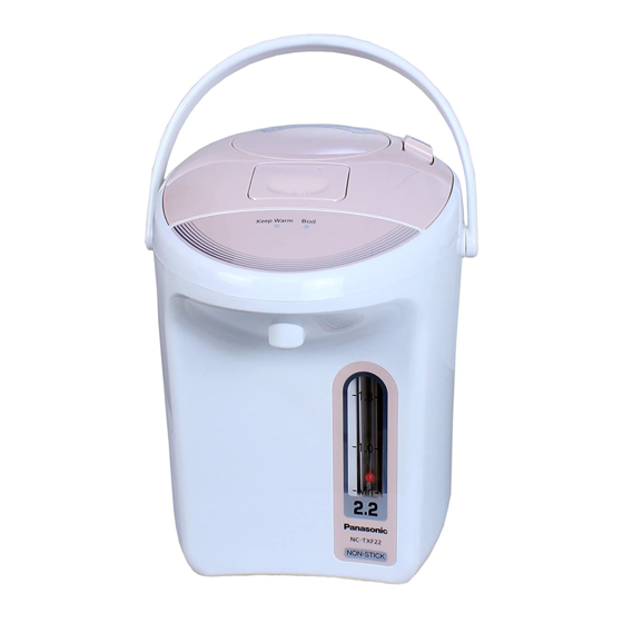
Electric Thermo Pot
WARNING
© Panasonic Appliances (Thailand) Co., Ltd. 2013.
All rights reserved. Unauthorized copying and
distribution is a violation of law.
NC-TXF22
NC-TXF30
Product Colour
Deep Gray (H)
Pink (P)
Destination
Thailand, Malaysia
Advertisement
Table of Contents

Related Manuals for Panasonic NC-TXF22


Summary of Contents for Panasonic NC-TXF22
- Page 1 Any attempt to service or repair the product or products dealt within this service information by anyone else could result in serious injury or death. © Panasonic Appliances (Thailand) Co., Ltd. 2013. All rights reserved. Unauthorized copying and distribution is a violation of law.
-
Page 2: Table Of Contents
NC-TXF22, NC-TXF30 CONTENT Page 1. Cautions for safe repair work 2. Specification 3. Problem checking 3.1 Thermo pot performance test mode 3.2 Dismantle procedure for failure diagnotics 3.3 Check points 3.4 Failure diagnostics chart 4. Disassembly and Reassembly instructions Bottom plate and Body Feed water pipe Thermal fuse comp. -
Page 3: Cautions For Safe Repair Work
NC-TXF22, NC-TXF30 1. CAUTIONS FOR SAFE REPAIR WORK To prevent accidents during repair work, injury or property loss to the users, safety instructions are described below. 1.1 Degree of loss or potential for injury is classified as follows. WARNING This indicates “ the possibility of death or serious injury ”... -
Page 4: Specification
NC-TXF22, NC-TXF30 2. SPECIFICATION MODEL NC-TXF22 NC-TXF30 Destination Thailand Thailand Malaysia Power Supply 220V 50Hz / C2 220V 50Hz / C2 240V 50Hz / S3 Power Consumption Rated 670W 670W 635W (approx.) Boiling 670W 670W 635W Capacity (approx.) 2.2 L 3.0 L... -
Page 5: Problem Checking
NC-TXF22, NC-TXF30 3. PROBLEM CHECKING Please follow check operating detail below, before LED symbol for this instruction show as below. start to check the problems. Lighted Blink 3.1 Thermo pot performance test mode Instruction Boiling and Keep warm test 1. Long Boil/Reboil LED will be lighted and LED will be blink and start to boil water. -
Page 6: Dismantle Procedure For Failure Diagnotics
NC-TXF22, NC-TXF30 3.2 Dismantle procedure for failure diagnotics Tapping screw (M4 x 12) Truss head screw CAUTION Thermo pot may break down by static electricity from clothes, human body, workbenches, etc., when touch or Bottom plate wonder to touch should to ground Screw A human body with several MΩ. -
Page 7: Failure Diagnostics Chart
NC-TXF22, NC-TXF30 3.4 Failure diagnostics chart 3.4.1 No power. (There is no power indication) The items in the Check correspond to those shown in Check Point on P. 6. Check Diagnostics Method Action Thermal fuse comp. Is there connection across the blue lead wire on the Replace the Thermal fuse comp. -
Page 8: Feed Water Pipe
NC-TXF22, NC-TXF30 4.2 Feed water pipe Tapping scraw (M4 x 8) 1. Remove 1 screw off. Feed water pipe 2. Remove bushing from water pipe packing A and container comp. 3. Remove feed water pipe from communicating Communicating bushing. bushing... -
Page 9: Case A Comp
NC-TXF22, NC-TXF30 4.4 Case A comp. 1. Remove water pipe comp., and then remove case A comp. 2. Pull off ball A from case A comp. Water pipe comp. Ball A Case A comp. FIG. 4 4.5 Lamp assy unit Tapping screw 1. -
Page 10: How To Remove Decoration Panel (Display Part)
NC-TXF22, NC-TXF30 4.6 How to remove Decoration panel (Display part) Open (A point) with minus screwdriver of small pin. KEEP WARM BOIL FIG. 6 4.7 Peg frame 1. Remove body follow the instruction. 2. Remove bottom ring upside with minus screwdriver or etc. -
Page 11: Guage Cover
NC-TXF22, NC-TXF30 4.8 Gauge cover Press clear part of gauge cover from inner body by thumb and remove it. Body Push by thumb Gauge cover FIG. 8 4.9 Lid comp. and Inner Lid 1. Remove 4 screws off. 2. Remove Inner lid off. -
Page 12: Lid Packing And Steam Way A
NC-TXF22, NC-TXF30 4.10 Lid packing and Steam way A 1. Remove steam way A. 2. Remove lid packing. Steam way A Lid packing FIG. 10 4.11 Lid and Pump comp. 1. Remove 4 screws off. Tapping screw 2. Use minus screwdriver to pry between lid (M4 x 10) and pump comp. -
Page 13: Valve A, Spring B And Seal Ring
NC-TXF22, NC-TXF30 4.12 Valve A, Spring B and Seal ring 1. Remove valve A from pump comp. 2. Remove spring B off. 3. Remove seal ring from valve A. Valve A Push Seal ring Spring B FIG. 12 4.13 Shaft Push lower part of pump comp., and push 4 legs of shaft then pull out. -
Page 14: Lock Knob A, Lock Spring A And Lock Spring B
NC-TXF22, NC-TXF30 4.14 Lock knob A, Lock spring A and Lock spring B 1. Catch lock spring A by wrench and pull out. 2. Follow the first section and remove lock Spring B. 3. Remove lock knob B off. Lock spring A... -
Page 15: Stopper Comp
NC-TXF22, NC-TXF30 4.16 Stopper comp. 1. Adjust lock pin of stopper comp. at “Release”. 2. Put minus screwdriver into stopper comp., gap and use power to remove it. Operating point After assemble, should to feel to touching of supporting plate on lock knob. -
Page 16: Upper Frame
NC-TXF22, NC-TXF30 4.18 Upper frame 1. Remove all the components attached to the cover plate and remove the cover plate. 2. Remove the case A comp. 3. Remove the control unit B (operation). 4. Remove the upper frame from the container comp. -
Page 17: Thermostat Assembly
NC-TXF22, NC-TXF30 4.20 Thermostat assembly 1. Set 2 ribs of hold spring A on cover plate to assemble thermostat assy. 2. Assemble hold spring A on cover plate. Spring grooves position Cover plate Thermostat Hold spring A FIG. 20 4.21 How to paste Decoration panel Paste Decoration panel tightly. -
Page 18: Shaft Assembly
NC-TXF22, NC-TXF30 4.22 Shaft assembly Set 4 legs of shaft into groove of pump comp., as picture below. Shaft Shaft Slot FIG. 22 4.23 Valve A, Seal ring and Spring B assembly 1. Assemble seal ring on valve A, then assemble spring B. -
Page 19: How To Check Pump Comp
NC-TXF22, NC-TXF30 4.24 How to check Pump comp. ① Use finger to Block position, and push tightly to prevent air leak from Lid. (If there is some rebound on Pump Comp., it means OK.) Operating point If do not set packing lid well, it may not withstand pushing reaction. (Packing lid should not be open) Assemble pump comp., to lid after check air leak. -
Page 20: Production No. Position
NC-TXF22, NC-TXF30 5. PRODUCTION NO. POSITION Production No. is located at bottome plate. Production date 6. BODY EFFICIENCY CHECK CAUTION For this test, please careful hot water. Amount of Pouring-out water checking. 1. Pour water into the container and change to boiling state. Waiting to keep warm mode. -
Page 21: Parts Exploded View And Replacement Parts List
NC-TXF22, NC-TXF30 7. PARTS EXPLODED VIEW AND REPLACEMENT PARTS LIST 7.1 Parts Exploded View : Body 34 35 (For Thailand) - 21 -... -
Page 22: Parts Exploded View : Packing
NC-TXF22, NC-TXF30 7.2 Parts Exploded View : Packing Polyethylene bag Instruction manual Written guarantee Plug comp. Pad B Pad A Protecting bag Pad C Carton box - 22 -... -
Page 23: Replacement Parts List 23
NC-TXF22, NC-TXF30 Important safety notice : Components identified by mark have special characteristics important for safety. When replacing any of these components, use only manufacturer’s specified part. 7.3 Replacement Part List : NC-TXF22, NC-TXF30 Parts List MODEL / Q’TY REF. -
Page 24: Parts List
NC-TXF22, NC-TXF30 Parts List MODEL / Q’TY REF. PART NAME PARTS NO. SAFETY REMARK TXF22 TXF30 HOLD SPRING A APE96T585 THERMOSTAT APS05-3751 PLUG COMP APN07T60010U THAILAND MODEL / C2 APN07M667-0U MALAYSIA MODEL / S3 CASE A COMP APC01H56210U BALL A... - Page 25 NC-TXF22, NC-TXF30 Screws MODEL / Q’TY REF. PART NAME PARTS NO. SAFETY REMARK TXF22 TXF30 PAN HEAD TAPPING SCREW XTN4+10CZM LID AND INNER LID DELTITE SCREW ANB1750J999A FEED WATER PIPE AND COVER PLATE SCREW A APK51-5291 BODY A AND CONTAINER...