Sharp CV-P09FR Service Manual
Hide thumbs
Also See for CV-P09FR:
- Installation and operation manual (144 pages) ,
- Mode d'emploi (23 pages) ,
- Installation and operation manual (23 pages)
Table of Contents
Advertisement
[1]
SPECIFICATION.................................... . ....... 1-1
[2]
ELECTRICAL PARTS ............................ . ....... 1-1
[3]
WIRING DIAGRAM ................................ . ....... 1-2
[4]
EXTERNAL DIMENSION....................... . ....... 1-2
[1]
PART NAMES ........................................ . ....... 2-1
[2]
LOCATION ............................................. . ....... 2-2
[3]
INCLUDED............................................. . ....... 2-3
[4]
HAUST HOSE........................................ . ....... 2-3
[5]
PRE-OPERATION CHECKS.................. . ....... 2-4
[6]
OPERATION MODE .............................. . ....... 2-4
[7]
DRAINAGE ............................................ . ....... 2-6
[8]
MAINTENANCE ..................................... . ....... 2-6
Parts marked with "
" are important for maintaining the safety of the set. Be sure to replace these parts with specified ones for
maintaining the safety and performance of the set.
SERVICE MANUAL
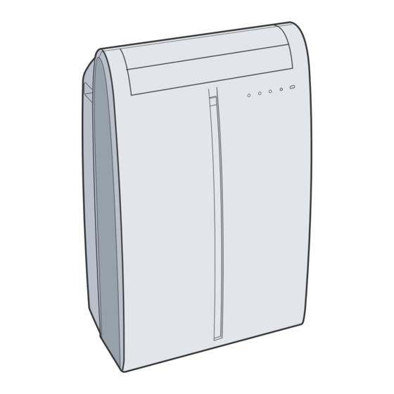
PORTABLE AIR CONDITIONER
CONTENTS
SHARP CORPORATION
CV-P09FR
MODEL
In the interests of user-safety (Required by safety regulations in some countries)
the set should be restored to its original condition and only parts identical to
those specified should be used.
[1]
PROCEDURE FOR DISASSEMBLY .............3-1
[2]
DISASSEMBLING THE CONTROL BOX ........3-9
ERATION
[1]
GRAM............................................................4-1
[2]
PRINTED WIRING BOARD...........................4-2
[3]
FUNCTION ....................................................4-3
[4]
PERFORMANCE CURVES...........................4-6
[1]
TROUBLESHOOTING ..................................5-1
This document has been published to be used
for after sales service only.
The contents are subject to change without notice.
CVP09FR
Advertisement
Table of Contents

Related Manuals for Sharp CV-P09FR


Summary of Contents for Sharp CV-P09FR
-
Page 1: Table Of Contents
CVP09FR SERVICE MANUAL PORTABLE AIR CONDITIONER CV-P09FR MODEL In the interests of user-safety (Required by safety regulations in some countries) the set should be restored to its original condition and only parts identical to those specified should be used. CONTENTS CHAPTER 1. -
Page 2: Chapter 1. Product Specification
CVP09FR CVP09FR Service Manual CHAPTER 1. PRODUCT SPECIFICATION [1] SPECIFICATION Cooling Capacity 2.12 Moisture Removal liters/h 1.17 Electrical Data Phase Single Rated frequency Rated voltage 220 - 240 Rated current Rated input Power factor 2.41 Compressor Type (Hermetically sealed rotary type) Model, Motor Output 5RS084DAC01 (600W) REFRIGERANT SYSTEM... -
Page 3: Wiring Diagram
CVP09FR [3] WIRING DIAGRAM CC089 220- 240V 50Hz TERMINAL 250V BOARD 3.15A 450V 2µF F 450V 2µF F 400V 20µ µ F [4] EXTERNAL DIMENSION Max. : 1500 1 – 2... -
Page 4: Chapter 2. Operation Instruction Part Names
CVP09FR CVP09FR Service Manual CHAPTER 2. OPERATION INSTRUCTION [1] PART NAMES 1. Front view Air Outlet Vertical louvers Horizontal louvers PLASMACLUSTER Lamp (blue) Remote control signal receiver window AUX. Button OPERATION Lamp (red TIMER Lamp (orange TURBO COOL Lamp (green Air inlet 2. -
Page 5: Location
CVP09FR 3. Remote control Transmitter Display ON/OFF Button DISPLAY Button TEMPERATURE Button PLASMACLUSTER Button 1 hr OFF Button MODE Button ON TIMER Button FAN Button OFF TIMER Button CANCEL Button SWING Button RESET Button TURBO COOL Button 4. Remote control display MODE SYMBOLS : COOL : DEHUMIDIFICATION... -
Page 6: Included
CVP09FR [3] INCLUDED Exhaust hose (1) Window exhaust adapter (1) Insect guard net (1) Hose clamp (1) Battery (2) Suction disk (1) Remote control (1) Manual (1) (AAA.R03) SUGGESTED TOOLS FOR WINDOW PANEL INSTALLATION 1. Screwdriver(medium size Phillips) 2. Tape measure or ruler 3. -
Page 7: Pre-Operation Checks
CVP09FR [5] PRE-OPERATION CHECKS LOADING BATTERIES HOW TO USE THE REMOTE CONTROL Use two AAA (R03) batteries. Remove the battery cover at the Point the remote control towards the back of the remote control. units signal receiver window and press the desired button. A beep will Insert batteries into the com- sound when the unit receives the partment, making sure the... -
Page 8: Fan Mode
CVP09FR 3. Fan mode 6. Turbo cool operation In this mode, the air conditioner simply circulates the air without cooling it. In this operation, the air conditioner fan works at extra high speed with a setting temperature of 15°C. Install the exhaust hose (See Page 8), turn the drainage nozzle to the CLOSE position, and check the drainage nozzle is covered with the stopcock. -
Page 9: Drainage
CVP09FR 8.2. On timer [7] DRAINAGE The unit will turn on automatically according to your setting . Timerduration canbe setfrom aminimum of half anhour (30minutes)to amaximum Prepare for drainage and drain out water within the unit in the following cases. of 12 hours. -
Page 10: Chapter 3. Disassembling Procedure
CVP09FR CVP09FR Service Manual CHAPTER 3. DISASSEMBLING PROCEDURE [1] PROCEDURE FOR DISASSEMBLY "ACTUAL UNITS MAY VARY SLIGHTLY FROM THOSE PICTURES BELOW" CAUTION: • DISCONNECT THE PORTABLE TYPE ROOM AIR CONDITIONER FROM THE POWER SUPPLY BEFORE ANY SERVICE. • DISCONNECT THE EXHAUST HOSE FROM THE UNIT BEFORE ANY SERVICE.(SEE PAGE 2-4) •... - Page 11 CVP09FR 5. Push down the orifice (at position of illustration), as shown in below 7. Unscrew 6 screws holding the side panel L and R. figure, to unhook 2 hooks of front panel. Remove side panel L and R. 8. Remove the stopcock from the drainpipe nozzle. 6.
- Page 12 CVP09FR 10.Remove the cabinet by lifting it up and pulling toward you as shown 13.Unscrew 2 screws holding the float switch ass’y. in below figure. Then move the float switch a little from bulkhead L. 11.Unscrew 4 screws holding the control box cover. 14.Unscrew 6 screws holding the bulkhead L.
- Page 13 CVP09FR 15.Unscrew 7 screws holding the stay angle L. 19.Remove the plasmacluster unit and cluster cover. Remove the stay angle L. Disconnect the connector of plasmacluster unit. 20.Unscrew 5 screws holding the top duct Remove the top duct 16.Unscrew 3 screws holding the led guide. Remove the led guide.
- Page 14 CVP09FR 22.Unscrew 2 screws holding the cover. 25.Cut the fixing band holding the wires.(1 part) 23.Unscrew 1screw holding the terminal board. 26.Cut the fixing band holding the wire and tape. Then remove the tape. CAUTION: KEEP THE TAPE IN CASE OF RE-ASSEMBLYING. Then cut the fixing band holding the wires.
- Page 15 CVP09FR 29.Remove wiring connectors of the compressor cord by using long- Then turn the band to the direction, as shown in below figure. nose pliers.(3 parts) CAUTION: RETURN THE BAND TO THE ORIGINAL DIRECTION WHEN RE-ASSEMBLYING. CAUTION: DISCHARGE THE FAN MOTOR CAPACITOR AND RUN- NING CAPACITOR BEFORE TOUCHING THESE CAPAC- 33.Move the band to the direction shown in below figure (approx.11/ ITORS OR OTHER COMPONENTS OR WIRING.
- Page 16 CVP09FR 36.Unscrew 4 screws holding the half plate. 38.Unscrew 6 screws holding the stay angle R. Remove the stay angle R from the unit. 39.Unscrew 3 screws holding the drain pump ass’y. Remove the drain pump ass’y from the unit. Then remove the half plate by lifting it up and pulling toward you as shown in below figure.
- Page 17 CVP09FR 42.Unscrew 4 screws holding the motor cover and wire holder. Remove the motor cover. Then remove the fan motor. 43.Unscrew the screw holding the centrifugal fan. 44.Unscrew 5 screws holding the motor cover and wire holder. Remove the motor cover. Then remove the fan motor.
-
Page 18: Disassembling The Control Box
CVP09FR [2] DISASSEMBLING THE CONTROL BOX CAUTION: DISCHARGE THE FAN MOTOR CAPACITOR AND RUNNING CAPACITOR BEFORE TOUCHING THESE CAPACITORS OR OTHER COMPONENTS OR WIRING. 1. Cut fixing bands holding the wires.(2 parts) 2. Remove 2 P.W.B. 3. Cut fixing bands holding the wires.(2 parts) Disconnect 6 connectors. -
Page 19: Chapter 4. Explanation Of Circuit And Op
CVP09FR CVP09FR Service Manual CHAPTER 4. EXPLANATION OF CIRCUIT AND OPERATION [1] ELECTRONIC CONTROL CIRCUIT DIAGRAM 4 – 1... -
Page 20: Printed Wiring Board
CVP09FR [2] PRINTED WIRING BOARD 4 – 2... -
Page 21: Function
CVP09FR [3] FUNCTION Indoor fan speed Customer Setting 1. Cool Operation Evaporator Temperature AUTO In the "COOL" mode, the thermostat circuit is controlled by 3 thermo- Lower than D3 stat lines(C1~C3). Higher than D3 When the difference between Room Temperature and Preset Temper- 12 /16°C ature is in [2]~[4] area, compressor is driving or starts driving. - Page 22 CVP09FR 7. Freeze preventive 8.3. ONE-HOUR TIMER When ONE-HOUR timer is set, the unit turns off automatically after When the indoor pipe temperature falls below 0ºC during cool opera- one hour. The one hour timer operation has priority over other time tion or dry operation, the compressor is turned off.
- Page 23 CVP09FR 14. SELF-CHECK MODE Louver Louver (Upper Side) (Lower Side) YELLOW GREEN BLUE Room Temp Eva Temp Cond Temp Test Input 44.6>107.6ºF 28.4>113.0ºF 28.4>113.0ºF P37 = H ~44.6ºF, ~28.4ºF, ~28.4ºF, P37 = L 107.6ºF~ 113.0ºF~ 113.0ºF~ Power On Start Function Select A Function Select B Select P44 = H...
-
Page 24: Performance Curves
CVP09FR [4] PERFORMANCE CURVES NOTE: 1) Use this data only as a guide to check the running condition. 2) The running conditions of this data is as follows. Remote control setting ....High cool, 18ºC Drain pump ........OFF Exhaust hose ........Shortest 3) This data will be changed by operation conditions such as: a drain pump operation or an exhaust hose configuration. -
Page 25: Chapter 5. Troubleshooting Guide
CVP09FR CVP09FR Service Manual CHAPTER 5. TROUBLESHOOTING GUIDE [1] TROUBLESHOOTING No cooling Any LED does not turn on Please check the diagnostic program(4-4). Some LED turn on. Check the display& Any fan or louver doesn't work detector unit. Some fan or louver work. - Page 26 CVP09FR Check the PWB (the control board) Change the fuse on PWB. The fuse on PWB is short. And check the cause of over current. The fuse was open. short Check the operation of Please check the diagnostic program(4-4). the product. Some LED turn on.
- Page 27 CVP09FR No cooling (Fan operate but the compressor doesn't operate.) under 100V Measure the power supply voltage at receptacle. Ask the power supply company for check. 120V(over 100V) insufficient Is it sufficient current capacity of power equipment ? Ask the power supply Is it small wiring for power company for check.
- Page 28 CVP09FR No cooling (The compressor operate but the indoor fan motor doesn't operate) crack at the solder part disconnecting the connector Check CN3 on PWB ass'y Repair with over solder. Connect the connector properly. Check the indoor fan motor capacitor. (6µF) Change the indoor fan motor capacitor Measure the resistance...
- Page 29 CVP09FR Should be performed drainage. Operation stops immediately and a (See step 6 and 7 "Whenever the unit is moved." TIMER, OPERATION, and MEGA of page 2-7.) COOL lamp blink. *CAUTION (Indicated of filled with water) It is possibility that the tank inside the unit has filled with condensation water.
- Page 30 CVP09FR The compressor doesn't turn off. disconnecting Check the thermistor connector. Connect the connector properly. Checking method for the compressor relay. (RY1 and PWB) Check the thermistor resistance. Turn off the power Change the thermistor. supply. Measure the contact short Check the compressor resistance.
- Page 31 CVP09FR Excessive vibration or Abnormal noise Excessive vibration or Abnormal noise in fan mode dirty Check the air filter not dirty Clean the air filter. Check rotating, direction of centrifugal fan.(to clockwise) Check the fan motor connector. Connect properly. Measure the resistance of fan motor coil.
- Page 32 CVP09FR MEMO 5 – 8...
-
Page 33: Replacement Parts List
CVP09FR REPLACEMENT PARTS LIST PORTABLE AIR CONDITIONER CV-P09FR MODEL CONTENTS OUTSIDE PARTS ACCESSORY PARTS INSIDE PARTS PACKING PARTS CONTROL BOX PARTS INDEX CYCLE PARTS “HOW TO ORDER REPLACEMENT PARTS” To have your order filled promptly and correctly, please furnish the following information. - Page 34 CVP09FR [1] OUTSIDE PARTS 1-76 6-19 1-73 1-64 1-60 1-70 1-71 1-80 1-68 1-61 1-72 1-78 1-55 1-74 1-77 1-66 6-22 1-137 1-81 1-115 6-24 1-65 1-67 6-24 1-62 6-24 1-63 1-75 6-24 1-35 1-79 6-24 1-59 1-69 6-16 6-25 1-57 1-58 1-56...
- Page 35 CVP09FR PRICE PART PARTS CODE DESCRIPTION RANK MARK RANK [1] OUTSIDE PARTS CABINET AND UNIT PARTS Cabinet ass'y CCAB-A395JBKZ Cabinet GCAB-A292JBFB LHLD-A735JBFB Cord holder TLAB-C748JBRZ Caution label TLAB-C804JBRZ Caution label TLAB-C805JBRZ Label TLAB-C806JBRZ Label 1-30 HDEC-B196JBEZ Display panel 1-33 TLAB-C747JBEZ Energy label 1-35 PSPA-A180JBEZ...
- Page 36 CVP09FR [2] INSIDE PARTS 6-24 1-82 6-19 1-86 1-45 1-121 6-24 1-138 6-24 6-24 1-103 6-20 1-104 6-24 1-46 1-100 1-106 6-24 1-91 1-117 6-19 1-51 6-24 6-24 1-52 1-102 1-101 1-121 1-19 1-20 1-85 1-50 1-17 1-18 1-20 1-19 1-24 1-23 2-2-(3)
- Page 37 CVP09FR PRICE PART PARTS CODE DESCRIPTION RANK MARK RANK [2] INSIDE PARTS CABINET AND UNIT PARTS Base pan ass'y CCHS-A914JBKZ Base pan ass'y DCHS-A536JBTA 1-10 NKOM-A001JBEZ Caster 1-11 PGUM-A164JBEZ Motor cushion 1-12 PGUM-A165JBEZ Motor cushion B 1-13 PGUM-A166JBEZ Motor cushion C 1-14 PGUMMA346JBEZ Drain plug...
- Page 38 CVP09FR [3] CONTROL BOX PARTS 2-20 6-46 2-11 2-17 1-32 6-44 2-13 -(1) 2-12 6-42 6-45 2-15 2-23 1-28 2-21 2-22 2-15 6-44 * Control board unit (2-2) consists of three units. 2-2-(1) · The main control unit. 2-2-(2) · The display & detector unit. 6-43 2-2-(3) ·...
- Page 39 CVP09FR [4] CYCLE PARTS 3-14 3-12 1-124 1-28 3-15 <TH2(OR)> 3-16 1-130 1-132 1-120 1-131 3-22 <TH1(YE)> 3-21 6-24 1-126 6-24 1-129 3-11 6-24 1-35 1-127 1-128 <TH3(BK)> 3-20 6-14 1-28 3-12 3-17 6-14 6-14 3-10 3-13 3-18 PRICE PART PARTS CODE DESCRIPTION RANK...
- Page 40 CVP09FR [5] ACCESSORY PARTS 4-10 4-23 4-17 4-16 4-11 4-26 4-24 4-25 PRICE PART PARTS CODE DESCRIPTION RANK MARK RANK [5] ACCESSORY PARTS PDUC-A011JBFB Duct hose PJNT-A007JBFB Connecter C SSAKAA109JBEZ Suction cap PPAC-A037JBEZ 4-10 Connecter ass'y CJNT-A003JBKZ 4-11 Remote control CRMC-A657JBEZ 4-16 Band 1/2...
- Page 41 CVP09FR [6] PACKING PARTS PRICE PART PARTS CODE DESCRIPTION RANK MARK RANK [6] PACKING PARTS CPADBA090JBKZ Bottom pad ass'y CPADBA091JBKZ Top pad ass'y SPAKCB878JBEZ Packing case SPADBA321JBEZ SSAKHA018JBEZ Protect SSAKHA245YDE0 Number card TLABKD859JBRZ...
- Page 42 CVP09FR INDEX PRICE PART PRICE PART PARTS CODE PARTS CODE RANK MARK RANK RANK MARK RANK MLOV-A410JBFA 2-1-20 [ C ] MLOV-A425JBTA 1-1-63 CCAB-A395JBKZ 1-1-1 CCHS-A914JBKZ 2-1-8 MLOV-A427JBTA 1-1-57 MLOV-A428JBTA 1-1-58 CFLO-A001JBKZ 2-1-108 MSPR-A005JBE0 4-3-5 CJNT-A003JBKZ 5-4-10 MSPR-A026JBE0 4-1-124 CKES-A162JBKZ 2-1-17 CKITTA071AKKZ 1-1-55...
- Page 43 CVP09FR PRICE PART PARTS CODE RANK MARK RANK PSRA-A172JBFA 2-1-16 PSRA-A173JBFZ 4-1-130 PSRA-A174JBFZ 4-1-129 [ Q ] QACC-A307JBZZ 3-2-1 QSW-MA009JBZZ 2-1-114 QTANZA022JBZZ 2-1-32 " 3-1-32 QW-IZA085JBZZ 4-1-131 QW-VZC366JBE0 4-1-132 QW-VZE964JBZZ 3-2-11 QW-VZE971JBZZ 1-1-80 QW-VZE985JBZZ 3-2-12 QW-VZE999JBZZ 3-2-13 QW-VZF060JBZZ 3-2-21 QW-VZF061JBZZ 3-2-22 QW-VZF129JBZZ 3-2-23...
- Page 44 COPYRIGHT © 2005 BY SHARP CORPORATION ALL RIGHTS RESERVED. No part of this publication may be reproduced, stored in retrieval systems, or transmitted in any form or by any means, electronic, mechanical, photocopying, recording, or otherwise, without prior written permission of the publisher.