Advertisement
Quick Links
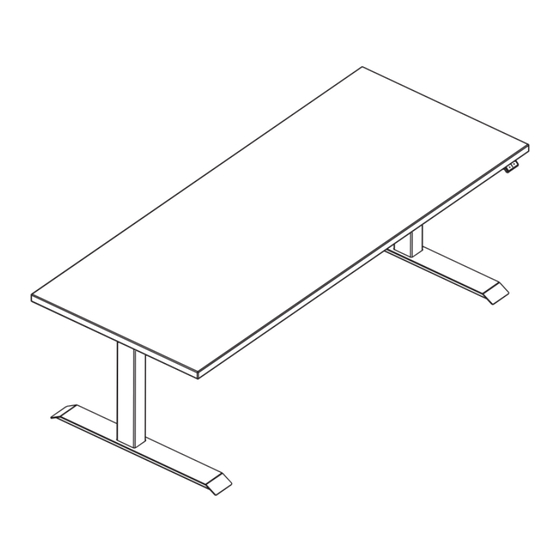
Assembly & Installation Instructions:
Essentia 2-Leg Workcenter ES2E54–72, ES3E54-72
Parts Included, Frame Set
A
Legs
Qty: 2
D
#M6 × 12 mm Flat Head Cap Screw
Qty: 12
L
#8 × ⅝" Pan Head Screw
Qty: 10
M
3/ 1 6" White Leg Cable Loops
Qty: 10
B
Rear Bracket
Qty: 2
Required & Sold Separately
Foot Kit
Basic or Programmable Switch
Top
Workrite Ergonomics | 800.959.9675 www.workriteergo.com
Box 1: 6608716-2PK-01
E
F
G
H
C
Connector Bracket
Qty: 1
Short Bracket
Qty: 2
Left End Bracket
Qty: 1
Right End Bracket
Qty: 1
4 mm Allen Wrench
Qty: 1
D
#M6 × 12 mm Flat Head Cap Screw
Qty: 8
I
#12 × ¾" Pan Head
Laminate Top Screw
Qty: 40
J
Control Box
Qty: 1
K
Cable Spool
Qty: 2
N
Power Cord
Qty: 1
Box 3: 6013312-5472-01
Box 2: 4435511-01
1 of 10
Advertisement

Related Manuals for Workrite ES2E54–72


Summary of Contents for Workrite ES2E54–72
- Page 1 Qty: 1 Box 3: 6013312-5472-01 Rear Bracket Connector Bracket #M6 × 12 mm Flat Head Cap Screw Qty: 2 Qty: 1 Qty: 8 Required & Sold Separately Foot Kit Basic or Programmable Switch Workrite Ergonomics | 800.959.9675 www.workriteergo.com 1 of 10...
- Page 2 Loading should be evenly distributed over table surfaces. “Payload Capacity” is the Workrite Ergonomics recommended maximum loading which includes the Workrite sourced table top.
- Page 3 #M6 × 12 mm Flat Head Cap Screw 61" Note! Only use the #M6 × 12 mm Flat Head Cap Screws for assembly. 70" Workcenters 55" 64" Workcenters 49" 58" Workcenters 43" 52" Workcenters Workrite Ergonomics | 800.959.9675 www.workriteergo.com 3 of 10...
- Page 4 Cap Screws for assembly. Use of longer screws will damage the legs. Note: The right bracket will be on your left and vice versa when the assembly is seen upside down. Left Bracket 4 of 10 Workrite Ergonomics | 800.959.9675 www.workriteergo.com...
- Page 5 Attach Base to Workrite Pre-Drilled Workrite Worksurface If you have a non-Workrite worksurface skip to Step 5. Note: For 2-Leg Corner and 120° Worksurface Mounting Instructions, go to: www.workriteergo.com/instructions Position leg assembly to align mounting holes in brackets to pre- drilled holes in worksurface.
- Page 6 #12×¾" Pan Head Laminate Top Screws (I). Tighten securely. 3 screws per Short Bracket 2 screws per End Bracket (2 installed in Step 5c) 16 screws per Rear Bracket Assembly 6 of 10 Workrite Ergonomics | 800.959.9675 www.workriteergo.com...
- Page 7 Attach Cable Spool (K) with the #12 × ¾" Pan Head Screw (I) to underside of worksurface. If you do not have a Workrite worksurface, mount Cable Spools (K) in a convenient location between Legs and Control Box. Lay out Switch and Leg Cables (A) to be sure they all reach the Control Box.
- Page 8 Attach 3/ 1 6" White Leg Cable Loops (M) to underside of worksurface using #8 × ⅝" Pan Head Screw (L) making sure to wrap the Cable Loop around the cable prior to attaching. If you do not have a Workrite worksurface, attach cable loops in a convenient locations between Legs or Switch and the Control Box.
- Page 9 Insert the Power Cord (N) into the power port on the Control Box (J). Leg Cable (A) into Leg Ports “M1” & “M2” Switch Cable into Switch Port “HS” Power Cord (N ) in Power Port Workrite Ergonomics | 800.959.9675 www.workriteergo.com 9 of 10...
-
Page 10: Cleaning Instructions
Suggested cleaners: Windex or Formula 409. Do not use solvents and do not saturate or spray cleaners directly onto workcenter base. ✓ Parts & Accessories Visit http://workriteergo.com/documentation/other/workrite_ergonomics_pricing_specification_guide.pdf replacement parts. 10 of 10 Workrite Ergonomics | 800.959.9675 www.workriteergo.com #1500244 Rev D...
Need help?
Do you have a question about the ES2E54–72 and is the answer not in the manual?
Questions and answers