Table of Contents
Advertisement
Quick Links
WARNING
Improper installation, adjustment, alteration, service
or maintenance can cause property damage, injury or
death. Read the installation, operating and
maintenance instructions thoroughly before installing
or servicing this equipment.
OWNER
Retain this Manual & ensure available for service.
Improper installation, adjustment, alteration, service
or maintenance can cause injury, death or property
damage.
Read the installation, operation and service
instructions thoroughly before installing or servicing
this equipment
Series THE
Installation, Operation and Service Instructions
INFRARED HEATER
Canada: 563 Barton Street, Stoney Creek, Ontario L8E 5S1
USA: 980 Cobb Place Blvd, NW#100 Kennesaw, GA 30144
www.superiorradiant.com
Page 1
SRP STEALTH
FOR YOUR SAFETY
Do not store or use gasoline or other flammable vapors
and liquids in the vicinity of this or any other appliance.
If you smell gas:
1. Open windows
2. Don't touch electrical switches
3. Extinguish any open flame
4. Immediately call your gas supplier
INSTALLER
Provide
Manual
to
Owner
installation!
Read and thoroughly understand these Instructions
before attempting any installation
HIGH EFFICIENCY
TWO STAGE
upon
completion
LT194 Feb 2017
of
Advertisement
Table of Contents
Troubleshooting

Related Manuals for Superior Radiant SRP STEALTH


Summary of Contents for Superior Radiant SRP STEALTH
- Page 1 Installation, Operation and Service Instructions INFRARED HEATER SRP STEALTH HIGH EFFICIENCY TWO STAGE WARNING FOR YOUR SAFETY Improper installation, adjustment, alteration, service Do not store or use gasoline or other flammable vapors or maintenance can cause property damage, injury or and liquids in the vicinity of this or any other appliance.
- Page 2 CAUTION: FIRE OR EXPLOSION HAZARD Maintain clearance to combustible constructions as further specified in this manual. Failure to do so could result in a serious fire hazard. Heaters should not be located in hazardous atmospheres containing flammable vapors or combustible dusts. Signs should be provided in storage areas specifying maximum safe stacking height.
-
Page 3: Table Of Contents
ONTENTS INTRODUCTION.................................. 4 .................................. 4 NSTALLATION ODES GENERAL SPECIFICATIONS .............................. 5 DIMENSIONAL CHARTS............................... 6 CONFIGURATION ................................ 6 PACKAGING CONTENTS .............................. 7 .................................. 8 ENERAL SSEMBLY .............................. 8 URNER BOX AND EAT XCHANGER CLEARANCE TO COMBUSTIBLES ............................ 9 HANGERS INSTALLATION AND HEATER SUSPENSION ...................... 1 0 VENTING & COMBUSTION AIR ............................ 1 1 ... -
Page 4: Introduction
INTRODUCTION Superior Radiant Products is a company in the infrared heating industry founded on the principles of product quality and customer commitment. Quality commitments are evidenced by superior design, a regard for design detail and an upgrade of materials wherever justifiable. -
Page 5: General Specifications
Gas Supply Lines Gas supply pipe sizing must be in accordance with the National Fuel Gas Code, ANSI Z223.1/NFPA 54 in the US and CSA B149.1 Installation Code in Canada. A 1/8" NPT plugged tap must be installed in the gas line connection immediately upstream of the burner farthest from the gas supply meter to allow checking of system gas pressure. -
Page 6: Dimensional Charts
DIMENSIONAL CHARTS Figure 1: Overall Dimensional Information CONFIGURATION Heat Exchanger Baffle High Rate Low Rate Model Length ft. (m) (BTU/Hr) (BTU/Hr) ft.(m) THE – 140 N 135,000 85,000 40 (12) 18 (5.4) Table 1: Configuration Information Series THE Page 6 LT194 Feb 2017... -
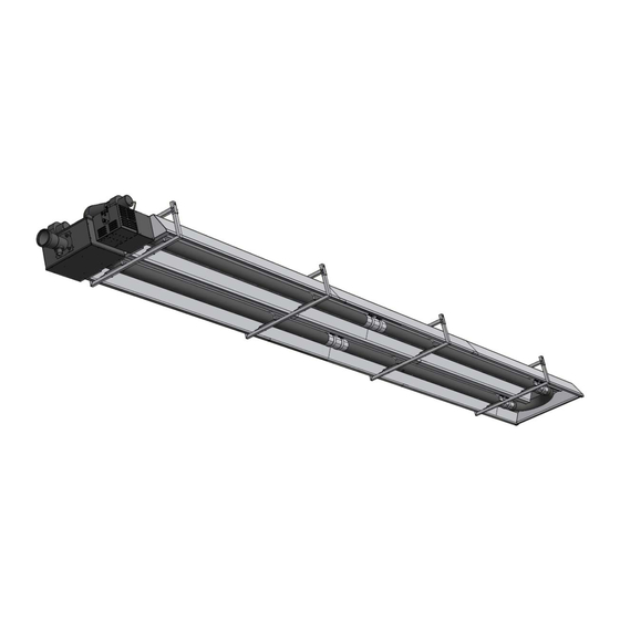
Page 7: Packaging Contents
PACKAGING CONTENTS Get to know your heater parts (list referencing Figures 1-2). Figure 2: General Overview Series THE Page 7 LT194 Feb 2017... -
Page 8: General Assembly
General Assembly Refer to Figure 2 for component identification. Description Description CR102 Canopy, burner section CT016 SS baffle with tab CR103 Canopy, middle section CT007+CT006 Baffle & baffle extension CR115 Canopy, u-tube section CR119 U-tube reflector end cap CR117 Reflectors CR105 Canopy end cap, u-tube side CR114... -
Page 9: Clearance To Combustibles
CLEARANCE TO COMBUSTIBLES A general clearance of 18” (46 cm) in every direction is recommended for servicing. In addition to this it is very important to observe the minimum clearance to combustibles at all times to avoid any possibility of property damage or personal injury. WARNING ... -
Page 10: Hangers Installation And Heater Suspension
HANGERS INSTALLATION AND HEATER SUSPENSION Suspension mechanism must allow for lateral tubing expansion. A minimum 12" (30 cm) length welded link chain with a working load limit of at least 200 lbs. is recommended (refer to Figure 5 for more details). SRP recommends and make available “quick links”... -
Page 11: Venting & Combustion Air
VENTING & COMBUSTION AIR General Requirements Refer to the National Fuel Gas Code, ANSI Z223.1 (NFPA 54) in the US and CSA B149.1 Installation Code in Canada, as well as all local requirements for general venting guidance. Heaters may be installed vented or unvented. ... -
Page 12: General Rules For Vent Terminals
General rules for vent terminals Be not less than 7’ (2.1 m) above grade when located adjacent to public walkways. Terminate at least 3’ (0.9 m) above any forced air inlet located within 10’ (3 m). Terminate at least 4’ (120 cm) below, 4’ (120 cm) horizontally from or 1’ (30 cm) above any door, window, or gravity inlet into any building. -
Page 13: Venting Configurations
Venting Configurations 4” PIPE MAXIMUM LENGTH 12’ (3.7 M) 6” PIPE MAXIMUM LENGTH 25’ (7.3 M) (PLUS UP TO TWO 87° ELBOWS) WALL AIR INTAKE 4” ADAPTOR (SUPPLIED) COLLAR 4” OR 6” PIPE TERMINAL WITH BIRD HEAT EXCHANGER SCREEN POINTED SIPHON DOWN TOWARDS THE GROUND 4” TO 6” ECCENTRIC ADAPTOR INSTALLATION SHOULD ALLOW CONDENSATION TO REACH THE DRAIN POINT FOR VENTING FOLLOW INSTALLATION INSTRUCTIONS OF VENT MANUFACTURER Horizontal venting ROOF TERMINAL WITH ROOF 4” PIPE MAXIMUM LENGTH 12’ (3.7M) FLASHING BIRD SCREEN FLASHING 6” PIPE MAXIMUM LENGTH 25’ (7.3M) (PLUS UP TO TWO 87° ELBOWS) ROOF MAINTAIN 12” (30CM) 18” (45CM) FOR CANADA MINIMUM CLEARANCE ABOVE HIGHEST ANTICIPATED 4” ADAPTOR SNOW LEVEL ... - Page 14 Figure 8: Unvented configuration (No external venting) Figure 9: Vented products with supplied fresh air Series THE Page 14 LT194 Feb 2017...
-
Page 15: Gas Piping
GAS PIPING The gas meter and service must be sufficiently large to supply gas to the connected building gas load including the heating equipment and any other gas fired equipment. Additionally, the gas distribution piping must be designed according to local and national ordinances. Generally (low pressure) systems designed with a maximum ½"... -
Page 16: High Limit Controls
Figure 11: Wiring Diagram using 24VAC Thermostat High Limit Controls Heat Exchanger High Limit Switch This device is located on the heat exchanger box and limits the maximum temperature of the heat exchanger. If the flue gas temperature rises above the temperature setting, the switch opens causing the heater to shut down. The switch will auto reset once the temperature drops sufficiently. -
Page 17: Burner Operation
BURNER OPERATION Starting sequence of operation Turn the thermostat up. When the thermostat calls for heat, both blower motors will energize. After blowers running, the air-proving switch closes and activates the ignition module. The ignition module, after a pre-purge period of approximately 30 seconds, energizes the igniter. Additionally, the gas valve is energized for this ignition trial period of 15 seconds. -
Page 18: Assembly Instructions Sequence
ASSEMBLY INSTRUCTIONS SEQUENCE Figure 12: General Overview of Installation Series THE Page 18 LT194 Feb 2017... -
Page 19: Assembly Preparation
Assembly preparation It is recommended that the heater is raised to its final position once the assembly has been completed. Prior to assembly identify all the components, Figure 2, 3, 11 and the order they will be assembled. Note that reflectors / canopy flanges are sitting lower than the tubes. - Page 20 4. Install couplers. When installing, orient band clamp lock bolts to top, at 10 o'clock or 2 o'clock position. 5. Locate / assemble tubes w/o flange 2 and 3. 6. Tighten clamping bolts of both couplers. Tube weld seam facing down. Torque coupling to 15-25 lb -ft (20-40 Nm).
-
Page 21: Reflectors Assembly
10. Locate and insert baffles at the opposite ends of the tubes to the burner: a. 6’ ( 183 cm) stainless steel on the 2nd tube b. 2 x 6’ (183 cm) baffles on the 3rd tube Baffles inserted at the opposite ends of the tubes to the burner. - Page 22 15. Install the reflector seal with the flanges facing inwards (secure with screws to reflectors and U- tube reflector). 4 x Self-drilling screw #8-18-1/2” 16. Install the U-tube reflector (overlap by 4” (100 mm), secure with screw to the reflectors and the reflector seal, 4 screws).
-
Page 23: Canopy And Endcaps Assembly
Canopy and endcaps assembly 19. Locate the reflector separators between the reflectors and canopy as shown in the Figure 12. Secure the reflector separator to the return tube side reflector with two screws. 8 x Self-drilling screw #8-18-1/2” 20. Locate and install the 1st canopy part. Slide the outer canopy over the reflectors from the U bend end ensuring correct location of reflector on the canopy flange. - Page 24 26. Install reflector endcaps on the burner side (two pieces) with the flanges facing outwards (secure with 6 screws to reflectors from inside). 2 x 6 x Self-drilling screw #8-18-1/2” 27. Install the canopy endcap (burner side) with the flanges facing inwards (secure canopy with screw, 8 screws).
-
Page 25: Burner Box, Heat Exchanger Installation
31. Secure one of the bottom reflector cover closer to the U-turn on the reflector seal with a screw. Secure the middle bottom reflector cover on the first one. The third bottom reflector cover will be secured on the middle cover. Allow about 1” (2.5 cm) between the cover edge and the canopy endcap flange. -
Page 26: Installation Checklist
INSTALLATION CHECKLIST Note: Use and complete this checklist before lighting the heater. Correct any conditions that do not meet these instructions. Heater assembly First hanging bracket 9" (225 mm) from the burner mounting flange. Radiant tube weld seam facing down Baffles inserted at the opposite ends of the tubes to the burner. -
Page 27: Troubleshooting
TROUBLESHOOTING Burner Blower / Motor Fails To Run Is the thermostat calling for heat? Is there 115V at the burner receptacle? Check blower for obstructions. Replace blower if necessary. Pressure Switch (N.O.) Failed Closed. Replace as necessary. ... -
Page 28: Troubleshooting Chart
Troubleshooting Chart Series THE Page 28 LT194 Feb 2017... -
Page 29: Replacement Parts
REPLACEMENT PARTS ITEM Part No. DESCRIPTION ITEM Part No. DESCRIPTION CE057 Indicator light CE010 Power Cord CE015 Ignition module CE006 Ignition wire CG057 Gas valve CS122 Heat exchanger housing CE058 Transformer CE277 Blower (Heat exchanger) CE276 Blower (Burner Box) CE279 Temperature Limit switch CE003 Flame Sensor Electrode... -
Page 30: Warranty
WARRANTY SERIES THE INFRARED HEATERS WARRANTY The manufacturer warrants to the original owner that the product will be free of defects in material and workmanship as described below. Component Warranty Period Burner & Controls 3 Years Heat Exchanger 10 Years Aluminized Radiant Tube with Post Purge 10 Years The Manufacturer’s obligation under this warranty is limited to repair or replacement, F.O.B.
Need help?
Do you have a question about the SRP STEALTH and is the answer not in the manual?
Questions and answers