Table of Contents

Related Manuals for Cutech 40180H-CT


Summary of Contents for Cutech 40180H-CT
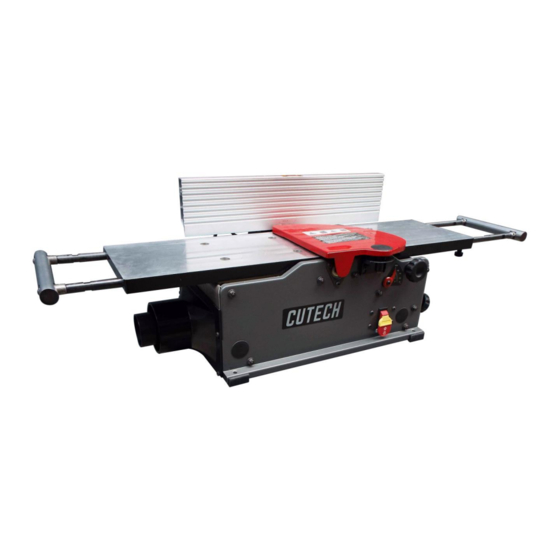
- Page 1 User Manual Read this manual before using machine to avoid serious injury and damage 40180H-CT/40180HC-CT 8” Bench Top Jointer with Spiral Style Cutterhead For technical support, email techservices@cutechtool.com or call at 877-568-8879 VER. 17.03.20...
-
Page 2: Table Of Contents
The drawings, illustrations, photographs, and specifications in this user manual represent your machine at time of print. However, changes may be made to your machine or this manual at any time with no obligation to CUTECH. -
Page 3: Warranty
2 YEAR LIMITED WARRANTY CUTECH warrants its machinery to be free of defects in workmanship and materials for a period of two (2) years from the date of the original purchase by the original owner. This warranty applies to products sold in United States only. The warranty does not apply to any product used for professional or commercial production purposes nor for industrial or educational applications. -
Page 4: Product Specifications
PRODUCT SPECIFICATIONS Cutterhead speed RPM 12,000 Motor RPM 19000+/-10% (No Load) Cutterhead diameter 2” Max width of cut 8" Max depth of cut 1/8" Cutter inserts qty Motor power input 120 V, 60 Hz, AC Only, 12 Amp 4-3/8” x 19-5/8” Fence Size Overall 8”... -
Page 5: General Safety
GENERAL SAFETY NOTE: The WARNING! and CAUTION! symbols indicate a potentially hazardous situation which, if not avoided, COULD result in death or serious injury. READ THIS MANUAL completely before assembling and operating this machine. WARNING! TO AVOID serious injury, death, or damage to the machine, please read, understand, and follow, all Safety and Operating Instructions before assembling and operating this machine. - Page 6 GENERAL SAFETY (cont.) ALWAYS keep the work area clean, well lit, and organized. DO NOT work in an area that has slippery floor surfaces from debris, grease, and wax. CAUTION! ALWAYS unplug the machine from the electrical receptacle when making adjustments, changing parts or performing any maintenance.
- Page 7 GENERAL SAFETY (cont.) KEEP protective guards in place and in working order. CAUTION! MAINTAIN your balance. DO NOT extend yourself over the tool. Wear oil resistant rubber soled shoes. Keep floor clear of debris, grease, and wax. MAINTAIN all machines with care. ALWAYS KEEP machine clean and in good working order. KEEP all blades and tool bits sharp.
-
Page 8: Product Safety
WARNING! DO NOT handle the plug or jointer with wet hands USE only accessories as described in this manual and recommended by CUTECH. 10. DO NOT pull the jointer by the power cord. NEVER allow the power cord to come in contact with sharp edges, hot surfaces, oil or grease. - Page 9 PRODUCT SAFETY (cont.) 14. ENSURE that the machine sits firmly before using. If the machine wobbles or is unstable, correct the problem by attaching to a bench top prior to operation. 15. This machine is designed to process wood ONLY. WARNING! NEVER position fingers or thumbs near the cutterhead.
-
Page 10: Grounding Instructions
GROUNDING INSTRUCTIONS WARNING! This machine MUST BE GROUNDED while in use to protect the operator from electric shock. In the event of a malfunction or breakdown, GROUNDING provides the path of least resistance for electric current and reduces the risk of electric shock. The plug MUST be plugged into a matching electrical receptacle that is properly installed and grounded in accordance with ALL local codes and ordinances. - Page 11 GROUNDING INSTRUCTIONS (cont.) Make certain the extension cord is properly sized, and in good electrical condition. Always replace a worn or damaged extension cord immediately or have it repaired by a qualified person before using it. Protect your extension cords from sharp objects, excessive heat, and damp or wet areas. MINIMUM RECOMMENDED GAUGE FOR EXTENSION CORDS (AWG) 115 VOLT OPERATION ONLY 25’...
-
Page 12: Unpacking & Inventory
If any parts are missing, do not attempt to plug in the power cord and turn “ON” the machine. The machine should only be turned “ON” after all the parts have been obtained and installed correctly. For missing parts, contact CUTECH at 877-568-8879. A. Jointer F. -
Page 13: Assembly
ASSEMBLY WARNING! MAKE CERTAIN THAT THE MACHINE IS DISCONNECTED FROM THE POWER SOURCE. FENCE ASSEMBLY PROCEDURE 1. Assemble the fence bracket (A) to the jointer base (B). Remove the four Soc Button Head Screws (C) on the rear frame to lock the bracket in place. SEE FIG. 1 2. - Page 14 ASSEMBLY (cont.) 3. Adjust the fence sliding bracket (A) to the middle of the fence (B), referring to the center of fence cut-out (C) use two M6x16mm soc button head screws (D) to lock the sliding bracket in position. SEE FIG. 3 4.
- Page 15 ASSEMBLY (cont.) 5. With the tilt lock lever assembly in between the mounting and sliding bracket, put on special nut (A), and turn the lever to lock both brackets into position. SEE FIG. 5 6. Use an angle gauge (A) to measure the 90° & 135° between the Fence and Jointer Table Top. Adjusting can be done by loosening or tightening the Nylok Hex Soc Head Screw (B).
-
Page 16: Section 9 Adjustments
ASSEMBLY (cont.) CUTTERHEAD GUARD The cutterhead guard has a tension return spring. The tension on this spring is set at the factory. When the guard is installed properly it should return to the fence automatically after the work piece has passed over the cutterhead. Be sure the guard is functioning properly every time before using the jointer. - Page 17 ASSEMBLY (cont.) LOCK KNOB ASSEMBLY Attach knob (A) to the jointer by tightening the hex nut (B) by 10 mm, 13mm open end wrench (C). SEE FIG. 10 & 11 SWITCH ASSEMBLY The jointer is turned on by flipping the switch into the up position and it is turned off by flipping the switch in the down position.
-
Page 18: Adjustments
ADJUSTMENTS WARNING! MAKE CERTAIN THAT THE MACHINE IS DISCONNECTED FROM THE POWER SOURCE BEFORE ANY ADJUSTMENTS ARE MADE. FENCE ADJUSTMENTS 1. To move the fence across the table by loosening lock lever (A), slide the fence to the desired position on the table and tighten lock lever (A). SEE FIG 13. FIG 13 NOTE: Lock lever (A) and (B) can be repositioned by pulling up the lever and repositioning it on the nut located underneath the lever. - Page 19 ADJUSTMENTS (cont.) 5. Tighten set screw (D) by hex wrench until it contacts stop (E) SEE FIG 16. FIG 16 . Put a square (C) on the table with one end against the fence to adjust the fence until it is exactly 135 degrees to the table.
- Page 20 ADJUSTMENTS (cont.) WARNING! MAKE CERTAIN THAT THE MACHINE IS DISCONNECTED FROM THE POWER SOURCE BEFORE ANY ADJUSTMENTS ARE MADE. INFEED / OUTFEED TABLE ADJUSTMENT The infeed and outfeed tables are adjustable for coplanar or parallelism if ever necessary. These are set at the factory. If after planing or edge joining a work piece and adjustment is necessary, follow these instructions.
- Page 21 ADJUSTMENTS (cont.) INFEED / OUTFEED EXTENSION SUPPORT ADJUSTMENT The infeed and outfeed extension supports are adjustable for coplanar or parallelism if ever necessary. These are set at the factory. If after planing or edge joining a work piece and adjustment is necessary, follow these instructions. At rear &...
-
Page 22: Operations
OPERATIONS NOTE: This operations section was designed to give instructions on the basic operations of this jointer. However, it is in no way comprehensive of every jointer operation. It is strongly recommended that you read books, trade magazines, or get formal training to maximize the potential of your jointer while minimizing the risks. - Page 23 OPERATIONS (cont.) DIRECTION OF GRAIN Avoid feeding work into the jointer against the grain. The result will be chipped and splintered edges. Feed with the grain to obtain a smooth surface. SEE FIG 19. FIG 19 The jointer can be set to cut any depth from a very thin shaving to 1/8” deep. The pointer on the scale is to indicate the depth of cut.
- Page 24 OPERATIONS (cont.) Refer to Table 20A for recommended maximum depth of cut for different board width of soft and hard woods. Table 20A Maximum depth of cut Board Width Soft Wood Hard Wood Less than 6” 1/8” 3/32” 7” 3/32” 5/64”...
- Page 25 OPERATIONS (cont.) PUSH BLOCKS CAUTION! A set of push blocks (A) should be used whenever possible to minimize all danger to your hands. SEE FIG 22 FIG 22 WARNING! ALWAYS USE PUSH BLOCKS WHEN PERFORMING SURFACING OPERATIONS AND NEVER PASS YOUR HANDS DIRECTLY OVER THE CUTTERHEAD. JOINTING AN EDGE This is the most common operation for the jointer.
-
Page 26: Maintenance
MAINTENANCE WARNING! MAKE CERTAIN THAT THE MACHINE IS DISCONNECTED FROM THE POWER SOURCE BEFORE PERFORMING ANY MAINTENANCE PROCEDURES Your jointer should provide you with a long time of service provided you take the time to perform the following maintenance operations. CLEANING Sawdust buildup and other debris can cause the tool to joint and plane incorrectly. - Page 27 MAINTENANCE (cont.) WARNING! MAKE CERTAIN THAT THE MACHINE IS DISCONNECTED FROM THE POWER SOURCE BEFORE PERFORMING ANY MAINTENANCE PROCEDURES BLADE (CUTTER INSERT) REPLACEMENT WARNING: To prevent serious personal injury NEVER rotate the cutterhead by hand. Cutter insert are razor sharp! Always wear heavy leather gloves when handling the cuttherhead.
- Page 28 MAINTENANCE (cont.) Note: Proper cleaning is critical to achieving a smooth finish. Dirt or dust trapped between the cutter insert and cutterhead will slightly raise the cutter insert and make noticeable marks on your work piece the next time you use the machine. REPLACING THE BELT Use 4MM Allen Key to loosen the screw of belt guard.
- Page 29 MAINTENANCE (cont.) Press the belt on the cutterhead pulley. SEE FIG 28. Then rotate cutterhead pulley on clockwise and assemble the belt. SEE FIG 29. FIG 28 FIG 29 Replace the belt guard. SEE FIG 30 and 31. FIG 30 FIG 31...
-
Page 30: Troubleshooting
TROUBLESHOOTING GUIDE Motor and Machine Operation PROBLEM LIKELY CAUSE SOLUTION Motor will not start. Not plugged in. Check the power source. Blown circuit. Replace fuse, reset breaker, or call Lockout key removed. electrician. Improper Voltage. Replace lockout key. Fuses or circuit Short circuit in line cord or plug. - Page 31 TROUBLESHOOTING GUIDE (cont.) PROBLEM LIKELY CAUSE SOLUTION Vibration when Loose or damaged cutter insert. Tighten or replace cutter insert. operating jointer Damaged belt. Replace belt Worn cutterhead bearing. Check/replace cutterhead bearing. Infeed table hard to Table lock is engaged or Completely loosen the table lock.
-
Page 32: Parts List
PARTS... - Page 34 DESCRIPTION DESCRIPTION TABLE CUTTERHEAD SHAFT RIGHT COVER CUTTER INSERT OUTFEED SUPPORT TORX SOCKET HEAD CAP SCREW SET SCREW REAR FRAME LEFT COVER HOLE PLUG BUTTON HD SCREW BEARING RETAINER SELF TAP SCREW TORX WRENCH DUST CHUTE DRIVE PULLEY FOAM SEAL CUTTERHEAD PULLEY FOAM SEAL BELT...
- Page 35 DESCRIPTION DESCRIPTION HEX NUT 133d SPECIAL SCREW SCREW 135S TILT LOCK LEVER ASSY FLAT WASHER 135a KNOB SCREW EXTENSION SUPPORT HANDLE FENCE SLIDE BRACKET EXTENSION SUPPORT LEVELING STUD FENCE BRACKET EXTENSION SUPPORT SLIDING POST FLAT WASHER PUSH BLOCK SOC BUTTON HD SCREW HEX WRENCH 300S MOTOR HEX WRENCH...
Need help?
Do you have a question about the 40180H-CT and is the answer not in the manual?
Questions and answers
Is there a trick to removing the cutterhead, it is all loose but cannot remove bearings. Circlip has been removed, also removed all nuts and allen screws from side covers. The is play between the bearings and the bearing holders creating lines. This has been a good machine for me.