Advertisement
Quick Links
Advertisement

Related Manuals for Ceriatone AFD 35


Summary of Contents for Ceriatone AFD 35
- Page 1 AFD #35 Hot Rodded Plexi Series 50W amplifier...
-
Page 2: Table Of Contents
Table of Contents 1) About the AFD…..…...…….…………………………………………………………………………………………page 2 2) Quick setup……………………………………………………………………………………………………………page 3 3) Front Panel controls………………………………………………………………………………………………….page 4 4) Rear Panel controls…………………………………………………………………………………………………..page 7 5) Tube compliment and external bias jacks and adjustment………………………………………………………page 9 6) Frequently Asked Questions………………………………………………………………………………………...page 13 1) About the AFD #35 100W amplifier Our British series of amplifiers has been overwhelmingly popular, and is still the backbone of our amplifier line. -
Page 3: Quick Setup
2) QUICK SETUP (for instant gratification) 1) Plug your guitar using a 1/4” instrument cable into the INPUT on the right of the front panel 2) Plug a suitable power cable from the AFD’s rear panel MAINS cable inlet to your wall power receptacle 3) Plug the AFD into your speaker cabinet using 1/4”... -
Page 4: Front Panel Controls
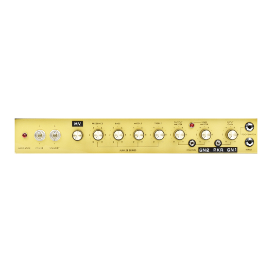
3) FRONT PANEL CONTROLS From left to right: 1) INDICATOR LED 2) POWER 2-way toggle switch 3) STANDBY 2-way toggle switch 4) “MV” (POST-PHASE INVERTER MASTER VOLUME) control 5) PRESENCE control 6) BASS control 7) MIDDLE control 8) TREBLE control 9) OUTPUT MASTER control 10) CHANNEL 2-way toggle switch 11) “GN2”... - Page 5 POWER two-way toggle switch powers the AFD on and off. With the toggle switch in the UP (“0”) position, the AFD is OFF. In the DOWN (“1”) position, the Yeti is ON. STANDBY applies high voltage to the vacuum tube anodes (and screen grids) during use of the Yeti. To ensure long tube life, first power the unit on with the toggle switch in UP (“0”) position for approximately 30 seconds.
- Page 6 Use this in conjunction with the “MV” to set both the volume level and degree of power amplifier saturation. In other words, nail the vibe and the level! CHANNEL switches between the two channels. In the UP position, it is the high-gain tone that made this amplifier famous. In the DOWN position, the tone is more traditional, not far off from a 2203 or 2204 series amplifier.
-
Page 7: Rear Panel Controls
4) REAR PANEL CONTROLS 1) FX SEND ¼” instrument jack 2) FX RETURN ¼” instrument jack 3) SPEAKERS ¼” speaker jacks (x2) 4) OUTPUT SELECTOR three-way rotary selector 5) BIAS TEST probe jacks (x5) 6) PENTODE / TRIODE SWITCH 2-way toggle switch 7) MAINS IEC cable inlet 8) MAINS FUSE T2A slow blow fuse 9) HT FUSE T500mA fuse... - Page 8 NOTE – never turn your amplifier to OPERATE mode (“1” / DOWN position on STANDBY) without connecting the amplifier to a speaker cabinet or suitable dummy load! Failing to do so may damage your amplifier! OUTPUT SELECTOR three-way rotary selector. Set to the position that matches the impedance of your speaker cabinet. NOTE –...
-
Page 9: Tube Compliment And External Bias Jacks And Adjustment
5) TUBE COMPLIMENT AND EXTERNAL BIAS JACKS AND ADJUSTMENT From left to right: V1 – 12AX7/ECC83 (input stage 1 and gain stage 2) V2 – 12AX7/ECC83 (gain stage 3) V3 – 12AX7/ECC83 (gain stage 4 and tonestack driver) V4 – 12AX7/ECC83 (phase inverter for power amplifier) V4 –... - Page 10 In this diagram, we have color coded five features for simplicity 1) Red (solid) arrow = probe jack, V5 2) Blue (solid) arrow = probe jack, V6 3) Green arrow = probe jack, GROUND 4) Orange (dashed) arrow = bias adjustment potentiometer shaft To measure your power tube bias, carefully follow these steps with the amplifier in OPERATE and connected to a speaker load (not doing so may damage your amplifier!):...
- Page 11 1) Turn on a digital multimeter (DMM), and set it to read millivolts (mV) in the 100mV range (this will vary from DMM to DMM) 2) Plug a black probe into the color-coded jack on your DMM, and do the same for a red probe 3) Insert the black probe tip into the GROUND probe jack (green arrow).
- Page 12 Even though the bias test points and adjustment is external to reduce risk of electrical shock, all precautions must be taken while biasing. Again, bias at your own risk. Ceriatone Amplification is not responsible for any damages or injuries resulting from user biasing.
-
Page 13: Frequently Asked Questions
FREQUENTLY ASKED QUESTIONS How do I hook up this thing? - See Section 2, beginning on page 3. Is the FX loop series or parallel? Active or passive? - The FX loop is series, and is currently parallel. However, we have plans to release an option for a tonally transparent solid-state FX loop. - Page 14 - Although you can try 12AT7s, 12AU7s, 5751s without any harm, the design is optimized for 12AX7s, and are therefore the only recommended tube in the preamp positions. Usage of other power tubes (ex – 6550s, 6L6GCs, modern 6V6s like Electro-Harmonix, JJ) may be possible, but please first consult Ceriatone Amplification or your local competent amplifier technician.
- Page 15 I like to use rack-mounted multieffects units. What is the output level straight from the EFFECTS LOOP SEND jack, -10dB or +4dB? - While not exact, -10dB is a better approximation than +4dB. The actual output level will depend on your settings, particularly the volume controls.
Need help?
Do you have a question about the AFD 35 and is the answer not in the manual?
Questions and answers