Keithley 2200 series Reference Manual
Programmable dc power supplies
Hide thumbs
Also See for 2200 series:
- Specification and performance verification technical reference (66 pages) ,
- User manual (38 pages) ,
- Operation manual (10 pages)

Related Manuals for Keithley 2200 series


Summary of Contents for Keithley 2200 series
- Page 1 Series 2200 Programmable DC Power Supplies Reference Manual 2200S-901-01 Rev. C / March 2016 *P2200S90101C* 2200S-901-01C A Grea t er M e a su r e of Co n f id e n c e...
- Page 2 Any unauthorized reproduction, photocopy, or use the information herein, in whole or in part, without the prior written approval of Keithley Instruments is strictly prohibited. All Keithley Instruments product names are trademarks or registered trademarks of Keithley Instruments. Other brand names are trademarks or registered trademarks of their respective holders.
-
Page 3: Safety Precautions
Keithley Instruments products are designed for use with electrical signals that are measurement, control, and data I/O connections, with low transient overvoltages, and must not be directly connected to mains voltage or to voltage sources with high transient overvoltages. - Page 4 (note that selected parts should be purchased only through Keithley Instruments to maintain accuracy and functionality of the product). If you are unsure about the applicability of a replacement component, call a Keithley Instruments office for information.
-
Page 5: Table Of Contents
Table of Contents Introduction ....................... 1-1 Welcome ..........................1-1 Extended warranty ....................... 1-1 Contact information ......................1-1 CD-ROM contents ........................ 1-2 Key features ......................... 1-2 Standard accessories ......................1-2 Optional accessories ......................1-3 Services available ........................ 1-3 Specifications ........................1-3 Electrical ratings for the power connection ................ - Page 6 Table of Contents Series 2200 Programmable DC Power Supplies Reference Manual Command and query structure ....................3-4 Command entry ......................... 3-5 Command groups ......................... 3-9 Command reference ....................4-1 Commands listed in alphabetical order ................4-2 *CLS (no query form) ......................4-2 CONFigure:SOUNd[:STATe] ....................
- Page 7 Series 2200 Programmable DC Power Supplies Reference Manual Table of Contents [SOURce:]OUTPut[:STATe] ....................4-20 [SOURce:]OUTPut:TIMer:DELay ..................4-21 [SOURce:]OUTPut:TIMer[:STATe] ..................4-22 [SOURce:]VOLTage[:LEVel] ....................4-23 [SOURce:]VOLTage:PROTection[:LEVel] ................. 4-24 [SOURce:]VOLTage:PROTection:STATe................4-25 [SOURce:]VOLTage:RANGe ..................... 4-26 *SRE........................... 4-27 STATus:OPERation:CONDition? (query only) ..............4-27 STATus:OPERation:ENABle ..................... 4-28 STATus:OPERation[:EVENt]? (query only) ...............
- Page 8 Index ........................... I-1 Table of Contents Series 2200 Programmable DC Power Supplies Reference Manual Next Steps ......................... 6-1 Additional Series 2200 information ..................6-1 Maintenance ......................A-1 Cleaning ..........................A-1 Calibration ......................... B-1 Performance verification ...................... B-1 Test record ..........................B-2 DC voltage accuracy with remote sense ...................
-
Page 9: Introduction
Specifications ................1-3 Welcome Thank you for using a Keithley Instruments product. The Series 2200 Programmable DC Power Supplies provide a wide range of voltage outputs to address the testing and characterization of components, circuits, modules, and complete devices whether you are in a research laboratory, in design and development, or in production test. -
Page 10: Cd-Rom Contents
• Additional product information: The product specifications are also included on the CD-ROM. For the latest drivers and additional support information, see the Keithley Instruments website The Keithley and Tektronix website - http://www.tek.com. Key features The Series 2200 offers: •... -
Page 11: Optional Accessories
(document number SPEC-2200S) on the Product Information CD-ROM that came with your Series 2200. For the latest version of the specifications, go to the Keithley Instruments website see The Keithley and Tektronix website - http://www.tek.com. 2200S-901-01 Rev. C / March 2016... -
Page 12: Electrical Ratings For The Power Connection
Section 1: Introduction Series 2200 Programmable DC Power Supplies Reference Manual Electrical ratings for the power connection Model Line selector Frequency Fuse rating Max power switch setting 2200-20-5 110 V / 220 V 50 / 60 Hz For 110 V: 5 A TH, 250 V 350 VA For 220 V: 2.5 A TH, 250 V 2200-30-5... -
Page 13: General Operation
Product Information CD-ROM that came with your Series 2200. For the latest version of the specifications, go to the Keithley Instruments website (http://www.tek.com/keithley). 1. Place the bottom of the instrument on a bench or similar surface. Do not stand the instrument on it's rear panel. - Page 14 Section 2: General operation Series 2200 Programmable DC Power Supplies Reference Manual Figure 1: Place bottom of instrument on flat stable surface 2. Before operating, ensure that the ambient temperature is between +0 °C and +40 °C (+32 °F to +104 °F).
-
Page 15: Installing The System
Series 2200 Programmable DC Power Supplies Reference Manual Section 2: General operation Installing the system This section contains information on how to install your Model 2200 power supply. • Unpack the instrument and check that you received all the items listed as standard accessories. •... - Page 16 Section 2: General operation Series 2200 Programmable DC Power Supplies Reference Manual Voltage output check To verify basic voltage functions without a load, follow these steps. 1. Remove all leads from the output connectors. 2. Turn on the power supply. 3.
-
Page 17: Operating Basics
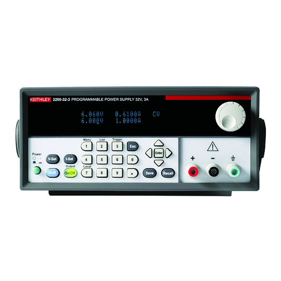
Series 2200 Programmable DC Power Supplies Reference Manual Section 2: General operation Operating basics Front panel at a glance The front panel of the Keithley Instruments Series 2200 contains the following items: • Power switch • Display • Arrow keys •... - Page 18 Section 2: General operation Series 2200 Programmable DC Power Supplies Reference Manual (3) Arrow keys Up, down, right, and left arrow keys (▲ and ▼) and Enter key. (4) Navigation wheel Rotate the navigation wheel to increase or decrease digits or to select menu items. (5) Output connectors Three banana jack output connectors provide high, low, and chassis ground connections.
- Page 19 Series 2200 Programmable DC Power Supplies Reference Manual Section 2: General operation Key descriptions The keys provide front panel control and configuration. See Front panel at a glance (on page 2-5) for an illustration of each key location. The following tables describe how to use each key. Key descriptions Keys Description...
- Page 20 Section 2: General operation Series 2200 Programmable DC Power Supplies Reference Manual Keypad special operations See the following table for the Series 2200 keypad special operations. Operation Key press Display the instrument firmware version. Shift + 8 Display the internal temperature of the instrument. Shift + .
- Page 21 Series 2200 Programmable DC Power Supplies Reference Manual Section 2: General operation Configuration menus description Use the configuration menus to configure (setup) the instrument. Sometimes the configuration menus are called the settings menus. See the following table for information on the primary menu selections, secondary menu selections, options, and a brief description of each selection.
- Page 22 Section 2: General operation Series 2200 Programmable DC Power Supplies Reference Manual Primary Secondary menu First option Additional Allows you to ... menu option(s) the instrument will advance to each step only after it receives a trigger signal. Repeat allows you to set or edit number of steps.
- Page 23 Series 2200 Programmable DC Power Supplies Reference Manual Section 2: General operation Primary Secondary menu First option Additional Allows you to ... menu option(s) Immediate Set rear panel port mode to immediate trigger. >RI Mode Turn remote inhibit (RI) mode off. Latching Set remote inhibit mode to latching.
- Page 24 Section 2: General operation Series 2200 Programmable DC Power Supplies Reference Manual Operating conditions Messages Description Power supply output is off. Instrument is operating in constant voltage (CV) mode. Instrument is operation in constant current (CC) mode. Instrument output has been turned off by the remote inhibit (RI) input. See [SOURce:]DIGital:FUNCtion (on page 4-12) for more information.
-
Page 25: Rear Panel At A Glance
Series 2200 Programmable DC Power Supplies Reference Manual Section 2: General operation Rear panel at a glance The rear panel of the Series 2200 contains the following items: • Cooling vents • Factory test port • USB device port • GPIB IEEE-488 port •... - Page 26 Section 2: General operation Series 2200 Programmable DC Power Supplies Reference Manual (2) Factory test port Do not use the factory test port. Unauthorized use of the factory test port could damage this product. (3) USB device port The USB 2.0 high-speed device port supports remote control and data transfer to a PC. (4) General purpose interface bus (GPIB) connector The GPIB supports remote control and data transfer to a PC.
-
Page 27: 110 V/220 V Selector Switch
Series 2200 Programmable DC Power Supplies Reference Manual Section 2: General operation 110 V/220 V selector switch The 110 V/220 V selector switch is located on the bottom of the instrument as shown in the following figure. Figure 5: Selector switch Front panel operation Within a few seconds after turning on, the power supply displays the actual voltage and current output value on the display’s top line and the voltage and current settings on the bottom line. - Page 28 Section 2: General operation Series 2200 Programmable DC Power Supplies Reference Manual Configuring the instrument for your application The configuration menus (see Configuration menus description (on page 2-9)) include settings, like OVP and Max Volt, that determine the maximum voltage output of the power supply. The menu system also includes settings, like Save Last and Output Recall, that determine how the instrument initializes itself when it is turned on.
-
Page 29: Setting The Current Limit
Series 2200 Programmable DC Power Supplies Reference Manual Section 2: General operation Initializing to the default setup Use the default setup to get the power supply into a default initial state: 1. Remove all leads from the output connectors. 2. Turn on the power supply. 3. - Page 30 Section 2: General operation Series 2200 Programmable DC Power Supplies Reference Manual Save and recall setups You can store up to 40 different setups in setup memory locations (1 to 40). Each setup includes the set voltage limit, the set current limit, and the protection menu settings. When shipped from the factory, setup memories 1 through 40 are empty.
- Page 31 Series 2200 Programmable DC Power Supplies Reference Manual Section 2: General operation Setting the overvoltage protection The OVP Set control turns overvoltage protection (OVP) on or off. If overvoltage protection is turned on and the instrument senses a voltage level above the threshold set for over-voltage control, the instrument will turn off the output and clamp the voltage on the output to below one volt.
- Page 32 Section 2: General operation Series 2200 Programmable DC Power Supplies Reference Manual Recall the power supply ON/OFF output state at power on The Output Recall control determines the On or Off output state after the power supply is powered on. If you select On, the power supply will restore the state of the output to that which was in use before the power was last turned off.
- Page 33 Series 2200 Programmable DC Power Supplies Reference Manual Section 2: General operation Recall the power supply operating parameters at power on The Save Last control determines whether the power supply saves its most recent settings, such as voltage and current, and restores these settings at power on. If you set this control to Off then the power supply returns to the default settings at power on.
- Page 34 Section 2: General operation Series 2200 Programmable DC Power Supplies Reference Manual Lock the navigation wheel The Knob Lock control can be used to lock the navigation wheel so it cannot be used to change settings or to select menu items. To lock the navigation wheel : 1.
- Page 35 Series 2200 Programmable DC Power Supplies Reference Manual Section 2: General operation Using remote sense Use remote sensing to regulate the output voltage at the device under test. This feature lets you compensate for the voltage drop in the leads between the power supply front-end terminals and the device-under-test.
- Page 36 Section 2: General operation Series 2200 Programmable DC Power Supplies Reference Manual Define a list of voltage and current steps The Edit List feature lets you create up to seven sequences of steps, each with a voltage level, current level, and time duration. To define and save a sequence, do the following: 1.
- Page 37 Series 2200 Programmable DC Power Supplies Reference Manual Section 2: General operation 7. Press Enter. The instrument displays: Repeat 1 8. Use the keypad or navigation wheel to select the number of times to repeat the list. In this example, 2 is used. This means that the instruction will run through the list of steps two times before stopping.
-
Page 38: Rear Panel Operation
Section 2: General operation Series 2200 Programmable DC Power Supplies Reference Manual Run a list of voltage and current steps To run a defined list of voltage and current steps, do the following: 1. Set the output voltage to what you want it to be set at before running the list and press the Output On/Off key to turn the output on. - Page 39 To avoid possible mechanical damage, stack no more than three connectors on any one unit. To minimize interference caused by electromagnetic radiation, use only shielded IEEE-488 cables. Contact Keithley Instruments for shielded cables. 2200S-901-01 Rev. C / March 2016 2-27...
- Page 40 Connect to an external computer with USB To connect to an external computer with USB: 1. Install a VISA driver on your computer. This driver is available on the Keithley Instruments website. 2. Connect the instrument to the computer with a USB cable. The computer will then recognize the power supply as a USB device.
-
Page 41: Operation Examples
Series 2200 Programmable DC Power Supplies Reference Manual Section 2: General operation Operation examples You can save tests in 40 memory locations to save up to 40 setups or use the Series 2200 List mode to define custom test sequences of up to 80 steps. This makes it easy to perform tests such as analyzing how your circuit or device under test performs at each voltage level within a range of voltages. -
Page 42: Timer Example
Section 2: General operation Series 2200 Programmable DC Power Supplies Reference Manual Timer example This example sets up the power supply to output 6 V, 1 A for 7 seconds before the output automatically turns off. Keystrokes Perform the following procedure using the keys on the instrument's front panel to save the test setup. To configure the duration of the timer and enable the timer feature: 1. - Page 43 Series 2200 Programmable DC Power Supplies Reference Manual Section 2: General operation Step number Voltage level (V) Current level (A) Duration (sec) 0.001 0.001 1.000 0.001 0.001 Keystrokes Use the following procedures to configure the list parameters,create the list steps, save the list, run, and stop running the list.
- Page 44 Section 2: General operation Series 2200 Programmable DC Power Supplies Reference Manual To configure the third step in the list: 1. Input S 003= 1.000 V. Press Enter. The display shows S 003= 0.0000A. 2. Input S 003= 1.000 A as the current limit. Press Enter. The display shows S 003= 1.0000S.
-
Page 45: Default Setup
Series 2200 Programmable DC Power Supplies Reference Manual Section 2: General operation Programming commands To reset the power supply: *RST To set the trigger source to be internal: TRIGGER:SOURCE:BUS To configure the list: SOURCE:LIST:STEP 5 SOURCE:LIST:MODE CONT SOURCE:LIST:COUT SOURCE:LIST:VOLT 1, 2V SOURCE:LIST:VOLT 2, 5V SOURCE:LIST:VOLT 3, 1V SOURCE:LIST:VOLT 4, 3V... -
Page 46: Clear And Sanitize Procedures
Section 2: General operation Series 2200 Programmable DC Power Supplies Reference Manual Clear and sanitize procedures This section helps customers with data security concerns to sanitize or remove memory devices from the Series 2200 instrument. These products have data storage (memory) devices and a data output device (USB port). These instructions tell how to clear or sanitize the memory devices and disable the data output device. -
Page 47: Memory Devices
Series 2200 Programmable DC Power Supplies Reference Manual Section 2: General operation Memory devices The following tables list nonvolatile and volatile memory devices. Detailed procedures to sanitize or clear these devices are shown after the tables. Nonvolatile memory devices Type and Function User Data input... -
Page 48: Data Export Devices
Section 2: General operation Series 2200 Programmable DC Power Supplies Reference Manual Data export devices The following table lists the data export device. There are no procedures to disable these devices. Data export device Type and Function User Data input method Location To disable minimum size... -
Page 49: Remote Operation
Interface Bus (GPIB). Using the USB Start by connecting a USB cable (Keithley Instruments Model USB-B - 1) between the USB 2.0 high- speed device port on the rear panel of your power supply and a computer. In order for the computer to recognize the power supply, a USBTMC driver must be installed on the computer. -
Page 50: Using The Gpib
Series 2200 Programmable DC Power Supplies Reference Manual Using the GPIB Connector for IEEE-488 (GPIB) operation. Use a shielded cable, such as the Keithley Instruments Model 7007-1 or Model 7007-2. Connect a GPIB cable from the Series 2200 instrument to your PC. -
Page 51: Command Syntax
Series 2200 Programmable DC Power Supplies Reference Manual Section 3: Remote operation Command syntax You can control the power supply through the GPIB or USB interface using commands and queries. This section describes the syntax these commands and queries use and the conventions the power supply uses to process them. -
Page 52: Command And Query Structure
Section 3: Remote operation Series 2200 Programmable DC Power Supplies Reference Manual Command and query structure Commands consist of set commands and query commands (usually simply called commands and queries). Commands change power supply settings or perform a specific action. Queries cause the power supply to return data and information about its status. -
Page 53: Command Entry
Series 2200 Programmable DC Power Supplies Reference Manual Section 3: Remote operation Commands Commands cause the power supply to perform a specific function or change one of its settings. Commands have the structure: [:]<Header>[<Space><Argument>[<Comma><Argument>]...] A command header is made up of one or more mnemonics arranged in a hierarchical or tree structure. - Page 54 Section 3: Remote operation Series 2200 Programmable DC Power Supplies Reference Manual SCPI commands and queries The power supply uses a command language based on the Standard Commands for Programmable Instruments (SCPI) standard. The SCPI standard was created by a consortium to provide guidelines for remote programming of instruments.
-
Page 55: Parameter Types
Series 2200 Programmable DC Power Supplies Reference Manual Section 3: Remote operation Parameter types Many power supply commands require parameters. Parameters are indicated by angle brackets, such as <file_name>. There are several different types of parameters, as listed in the following table. The parameter type is listed after the parameter. - Page 56 Section 3: Remote operation Series 2200 Programmable DC Power Supplies Reference Manual Chaining commands and queries You can chain several commands or queries together into a single message. To create a chained message, first create a command or query, then add a semicolon (;), and finally add more commands or queries and semicolons until you are done.
-
Page 57: Command Groups
(on page 4-2) section provides details on each command. The power supply interface conforms to Keithley standard codes and formats except where noted. The GPIB interface also conforms to IEEE Std 488.2–1987 except where noted. The USB interface also conforms to USB Test and Measurement Class, Subclass USB488 Specification, except where noted. -
Page 58: Command Reference
Section 4 Command reference In this section: Commands listed in alphabetical order ........4-2 *CLS (no query form) ............... 4-2 CONFigure:SOUNd[:STATe] ............ 4-3 *ESE ..................4-3 *ESR? (query only) ..............4-4 FETCh:CURRent[:DC]? (query only) ........4-4 FETCh:VOLTage[:DC]? (query only) ........4-5 FETCh[:SCALar]:POWer? (query only) ........ -
Page 59: Commands Listed In Alphabetical Order
Section 4: Command reference Series 2200 Programmable DC Power Supplies Reference Manual SYSTem:KEY ................. 4-35 SYSTem:LOCal (no query form) ..........4-36 SYSTem:POSetup ..............4-36 SYSTem:REMote (no query form) ......... 4-37 SYSTem:RWLock (no query form) ......... 4-37 SYSTem:VERSion? (query only) ........... 4-37 *TRG (no query form) ............. -
Page 60: Configure:sound[:State]
Series 2200 Programmable DC Power Supplies Reference Manual Section 4: Command reference CONFigure:SOUNd[:STATe] This command turns the key beep sound on or off. Group System Syntax CONFigure:SOUNd[:STATe] {0|1|ON|OFF} CONFigure:SOUNd[:STATe]? Arguments 0 or OFF turns the key beep sound off. 1 or ON turns the key beep sound on. Returns Examples CONF:SOUN:OFF... -
Page 61: Esr? (Query Only)
Section 4: Command reference Series 2200 Programmable DC Power Supplies Reference Manual *ESR? (query only) Returns the contents of the Standard Event Status Register (SESR). *ESR? also clears the SESR (since reading the SESR clears it) See Appendix C, Registers (on page C-3) for more information about SESR. -
Page 62: Fetch:voltage[:Dc]? (Query Only)
Series 2200 Programmable DC Power Supplies Reference Manual Section 4: Command reference FETCh:VOLTage[:DC]? (query only) This command returns the last measured output voltage stored in the communications buffer of the power supply. A new measurement is not initiated by this command. Group Measurement Syntax... -
Page 63: Idn? (Query Only)
XX-X.XX. X.XX-X.XX Examples *IDN? might return the following response for a 2200-72-1 instrument: Keithley Instruments, 2200-72-1, 081003126672201022, 1.25-1.23 MEASure:CURRent[:DC]? (query only) This command initiates and executes a new current measurement, and returns the measured output current of the power supply. -
Page 64: Measure:voltage[:Dc]? (Query Only)
Series 2200 Programmable DC Power Supplies Reference Manual Section 4: Command reference MEASure:VOLTage[:DC]? (query only) This command initiates and executes a new voltage measurement, and returns the measured output voltage of the power supply. Group Measurement Syntax MEASure:VOLTage[:DC]? Related FETCh:VOLTage[:DC]? (query only) (on page 4-5) Commands Returns... -
Page 65: Psc
Section 4: Command reference Series 2200 Programmable DC Power Supplies Reference Manual *PSC Sets and queries the power-on status flag that controls the automatic power-on execution of SRER and ESER. When *PSC is true, the SRER and ESER are set to 0 at power-on. When *PSC is false, the current values in the SRER and ESER are preserved in nonvolatile memory when power is shut off and are restored at power-on. -
Page 66: Rcl (No Query Form)
Series 2200 Programmable DC Power Supplies Reference Manual Section 4: Command reference *RCL (no query form) Restores the state of the power supply from a copy of its settings stored in the setup memory. The settings are stored using the *SAV command. -
Page 67: [Source:]Current[:Level]
Section 4: Command reference Series 2200 Programmable DC Power Supplies Reference Manual Saves the state of the power supply into a specified nonvolatile memory location. Any settings that had been stored previously at the location are overwritten. You can later use the *RCL command to restore the power supply to this saved state. -
Page 68: [Source:]Digital:data
Series 2200 Programmable DC Power Supplies Reference Manual Section 4: Command reference [SOURce:]DIGital:DATA This command sets the output state of the rear-panel TTL control output and queries the state of the rear-panel TTL control input. When the port mode is DIGITAL, this command is enabled. Group Source Syntax... -
Page 69: [Source:]Digital:function
Section 4: Command reference Series 2200 Programmable DC Power Supplies Reference Manual [SOURce:]DIGital:FUNCtion This command sets or queries the function of the TTL control lines on the rear panel of the power supply. *RST value is TRIGger. Group Source Syntax [SOURce:]DIGital:FUNCtion {TRIGger|RIDFi|DIGital} [SOURce:]DIGital:FUNCtion? Related... -
Page 70: [Source:]Function:mode
Series 2200 Programmable DC Power Supplies Reference Manual Section 4: Command reference [SOURce:]FUNCtion:MODE This command can be in either fixed mode or list mode. When this command is in fixed mode, the power supply responds to discrete commands. When this command is in list mode, the power supply operates in list mode. -
Page 71: [Source:]List:current[:Level]
Section 4: Command reference Series 2200 Programmable DC Power Supplies Reference Manual Returns <NR1> is the number of times the active list is set to execute. Examples LIST:COUNT 6 would set the active list to execute 6 times before stopping. [SOURce:]LIST:CURRent[:LEVel] This command sets the current for a list step in units of A or mA. -
Page 72: [Source:]List:mode
Series 2200 Programmable DC Power Supplies Reference Manual Section 4: Command reference [SOURce:]LIST:MODE This command determines the response of the power supply to a trigger in list mode. Group Source Syntax [SOURce:]LIST:MODE {CONTinuous|STEP}[SOURce:]LIST:MODE? Related [SOURce:]LIST:COUNt (on page 4-13), Commands [SOURce:]LIST:STEP (on page 4-16) Arguments CONTinuous: Sets the power supply to execute the entire list in... -
Page 73: [Source:]List:save (No Query Form)
Section 4: Command reference Series 2200 Programmable DC Power Supplies Reference Manual [SOURce:]LIST:SAVe (no query form) This command saves the active list file to a storage location in non- volatile memory. Group Source Syntax [SOURce:]LIST:SAVe <NR1> Related [SOURce:]LIST:RCL (no query form) (on page 4-15) Commands Arguments... -
Page 74: [Source:]List:voltage[:Level]
Series 2200 Programmable DC Power Supplies Reference Manual Section 4: Command reference [SOURce:]LIST:VOLTage[:LEVel] This command sets the voltage level of a specified step in a list in units of V or mV. Group Source: List Syntax [SOURce:]LIST:VOLTage[:LEVel] <NR1>,<voltage> Arguments <NR1> is an integer in the range from 1 to 80, which is a step number in the active list. -
Page 75: [Source:]Output:dfi:source
Section 4: Command reference Series 2200 Programmable DC Power Supplies Reference Manual [SOURce:]OUTPut:DFI:SOURce This command associates the DFI TTL output on the rear panel with a specified bit in the status byte register (SBR). Once the bit is associated with the DFI signal, the DFI signal will reflect the state of the specified bit. -
Page 76: [Source:]Output:pon[:State]
Series 2200 Programmable DC Power Supplies Reference Manual Section 4: Command reference [SOURce:]OUTPut:PON[:STATe] This command configures the power supply to power up with its output turned off, or to return the output to the state it was in when it powered down. Group Source Syntax... -
Page 77: [Source:]Output:ri:mode
Section 4: Command reference Series 2200 Programmable DC Power Supplies Reference Manual [SOURce:]OUTPut:RI:MODE This command sets the input mode of the RI (remote inhibit) input pin. In order for this command to be effective, the rear panel TTL input and output must be configured in RI/DFI mode using the [SOURce:]DIGital:FUNCtion (on page 4-12) command. -
Page 78: [Source:]Output:timer:delay
Series 2200 Programmable DC Power Supplies Reference Manual Section 4: Command reference Examples OUTPUT ON OUTPUT? might return 0, which would indicate that the output is off. [SOURce:]OUTPut:TIMer:DELay This command sets the time duration of the output timer. When the timer is activated and a duration is set, the output of the power supply will turn off automatically if left on longer than the specified duration. -
Page 79: [Source:]Output:timer[:State]
Section 4: Command reference Series 2200 Programmable DC Power Supplies Reference Manual [SOURce:]OUTPut:TIMer[:STATe] This command turns the output timer function on and off. When the timer is activated and a duration is set, the output of the power supply will turn off automatically if left on longer than the specified duration. -
Page 80: [Source:]Voltage[:Level]
Series 2200 Programmable DC Power Supplies Reference Manual Section 4: Command reference [SOURce:]VOLTage[:LEVel] This command sets the voltage value of the power supply. Group Source Syntax [SOURce:]VOLTage[:LEVel] {<NRf>|MIN|MAX|DEF} [SOURce:]VOLTage[:LEVel]? Related [SOURce:]CURRent[:LEVel] (on page 4-10) Commands Arguments <voltage> where: <voltage>::=<NRf><units> <NRf> is a flexible decimal specifying the voltage setting, ranging from 0 to the maximum nameplate voltage of the power supply. -
Page 81: [Source:]Voltage:protection[:Level]
Section 4: Command reference Series 2200 Programmable DC Power Supplies Reference Manual [SOURce:]VOLTage:PROTection[:LEVel] This command sets the over voltage protection (OVP) threshold level. Group Source Syntax [SOURce:]VOLTage:PROTection[:LEVel] {<voltage>|MIN|MAX|DEF} [SOURce:]VOLTage:PROTection[:LEVel]? Related [SOURce:]VOLTage:PROTection[:LEVel] (on page 4-24) Commands [SOURce:]VOLTage:RANGe (on page 4-26) Arguments <voltage>::=<NRf><units>... -
Page 82: [Source:]Voltage:protection:state
Series 2200 Programmable DC Power Supplies Reference Manual Section 4: Command reference [SOURce:]VOLTage:PROTection:STATe This command activates, deactivates, or checks the status of overvoltage protection (OVP). Group Source Syntax [SOURce:]VOLTage:PROTection:STATe {0|1|OFF|ON} [SOURce:]VOLTage:PROTection:STATe? Related [SOURce:]VOLTage:PROTection[:LEVel] (on page 4-24) Commands [SOURce:]VOLTage:RANGe (on page 4-26) Arguments 0 or OFF sets the over voltage protection to off. -
Page 83: [Source:]Voltage:range
Section 4: Command reference Series 2200 Programmable DC Power Supplies Reference Manual [SOURce:]VOLTage:RANGe This command limits the maximum voltage that can be programmed on the power supply. This command corresponds to the front-panel Max Voltage setting that can be found under the Protection submenu. -
Page 84: Sre
Series 2200 Programmable DC Power Supplies Reference Manual Section 4: Command reference *SRE Service request enable (SRE) sets and queries the bits in the service request enable register (SRER). See Appendix C, Registers (on page C-3) for more information about SRER. Group Status Syntax... -
Page 85: Status:operation:enable
Section 4: Command reference Series 2200 Programmable DC Power Supplies Reference Manual SRER have the binary value 00100000. STATus:OPERation:ENABle This command sets and queries the contents of the operation enable register (OENR). The OENR is an eight-bit mask register that determines which bits in the Operation Event Register (OEVR) will affect the state of the OPER bit in the Status Byte Register (SBR). -
Page 86: Status:operation[:Event]? (Query Only)
Series 2200 Programmable DC Power Supplies Reference Manual Section 4: Command reference STATus:OPERation[:EVENt]? (query only) This command returns the contents of the operation event register (OEVR). After executing this command the operation event register is reset. Details about the status registers are available in Appendix Registers (on page C-3). -
Page 87: Status:questionable:enable
Section 4: Command reference Series 2200 Programmable DC Power Supplies Reference Manual STATus:QUEStionable:ENABle This command sets and queries the contents of the questionable enable register (QENR). The QENR is an eight-bit mask register that determines which bits in the Questionable Event Register (QEVR) will affect the state of the QUES bit in the Status Byte Register (SBR). -
Page 88: Status:questionable[:Event]? (Query Only)
Series 2200 Programmable DC Power Supplies Reference Manual Section 4: Command reference STATus:QUEStionable[:EVENt]? (query only) This command returns the contents of the questionable event register (QEVR). After executing this command, the quest event register is reset. Details about the QEVR are available in Appendix Registers (on page C-3). -
Page 89: Status:questionable:ntransition
Section 4: Command reference Series 2200 Programmable DC Power Supplies Reference Manual STATus:QUEStionable:NTRansition This command sets the negative transition filter of the questionable event register. The filter contents cause the corresponding bit in the questionable event register to become 1 when the bit value of the questionable condition register transitions from 1 to 0. -
Page 90: Status:questionable:ptransition
Series 2200 Programmable DC Power Supplies Reference Manual Section 4: Command reference STATus:QUEStionable:PTRansition This command sets the positive transition filter of the questionable event register. The filter contents cause the corresponding bit in the questionable event register to become 1 when the bit value of the questionable condition register transitions from 0 to 1. -
Page 91: Stb? (Query Only)
Section 4: Command reference Series 2200 Programmable DC Power Supplies Reference Manual *STB? (query only) The byte query returns the contents of the status byte register (SBR) using the Master Summary Status (MSS) bit. Refer to Appendix C, Registers (on page C-3) for more information. Group Status Syntax... -
Page 92: System:key
Series 2200 Programmable DC Power Supplies Reference Manual Section 4: Command reference SYSTem:KEY This command can produce the same effect as pressing one of the front-panel buttons. The instrument must be in local mode in order for this command to simulate a front-panel button press. Group System Syntax... -
Page 93: System:local (No Query Form)
Section 4: Command reference Series 2200 Programmable DC Power Supplies Reference Manual SYSTem:LOCal (no query form) This command sets the power supply for control from the front- panel. Group System Syntax SYSTem:LOCal Related SYSTem:LOCal (no query form) (on page 4-36) Commands SYSTem:RWLock (no query form) (on page 4-37) -
Page 94: System:remote (No Query Form)
Series 2200 Programmable DC Power Supplies Reference Manual Section 4: Command reference SYSTem:REMote (no query form) This command sets the power supply to remote control mode. Group System Syntax SYSTem:REMote Related SYSTem:LOCal (no query form) (on page 4-36) Commands SYSTem:RWLock (no query form) (on page 4-37) Arguments None. -
Page 95: Trg (No Query Form)
Section 4: Command reference Series 2200 Programmable DC Power Supplies Reference Manual *TRG (no query form) This command generates a trigger event. Group Trigger Syntax *TRG Related TRIGger[:IMMediate] (no query form) (on page 4-38) Commands Examples *TRG TRIGger[:IMMediate] (no query form) This command forces an immediate trigger event. -
Page 96: Trigger:source
Series 2200 Programmable DC Power Supplies Reference Manual Section 4: Command reference TRIGger:SOURce This command sets the source of trigger events. Group Trigger Syntax TRIGger:SOURce {MANual|IMMediate|EXTernal|BUS} TRIGger:SOURce? Related [SOURce:]DIGital:FUNCtion (on page 4-12) Commands *TRG (no query form) (on page 4-38) TRIGger[:IMMediate] (no query form) (on page 4-38) Arguments... -
Page 97: Wai (No Query Form)
Section 4: Command reference Series 2200 Programmable DC Power Supplies Reference Manual *WAI (no query form) This command prevents the instrument from executing further commands or queries until all pending commands are complete. Group Synchronization Syntax *WAI Examples *WAI Programming examples This topic provides the following programming examples: 4-40 2200S-901-01 Rev. -
Page 98: Example 1
Series 2200 Programmable DC Power Supplies Reference Manual Section 4: Command reference Example 1 This example is written in the C programming language, the Virtual Instrument Software Architecture (VISA) standard can be used. It demonstrates basic communication with the power supply and error checking. - Page 99 Section 4: Command reference Series 2200 Programmable DC Power Supplies Reference Manual reading CheckError("Unable to read voltage"); ErrorStatus = viPrintf(PWS4000,"MEASURE:CURRENT?\n"); //measure the output current CheckError("Unable to write the device"); ErrorStatus = viScanf(PWS4000,"%f",¤t); //retrieve reading CheckError("Unable to read current"); printf("Measured voltage(V) & current(A): %f,%f \n", voltage, current);...
-
Page 100: Example 2
Series 2200 Programmable DC Power Supplies Reference Manual Section 4: Command reference clock_t goal; goal = wait + clock(); while(goal > clock()); Example 2 This example shows a command sequence that configures a three-step list to execute once in continuous mode. It saves the list in location 1, and then places the instrument in list mode and runs the list. -
Page 101: Example 4
Section 4: Command reference Series 2200 Programmable DC Power Supplies Reference Manual Example 4 This example is written in the C programming language; NI VISA can be used. The program demonstrates setting up and executing a list. It shows how to use the Operation Condition Register to determine when the list has finished executing. - Page 102 Series 2200 Programmable DC Power Supplies Reference Manual Section 4: Command reference SendSCPI("VOLTAGE 0V"); //set the voltage to 0V SendSCPI("OUTPUT 1"); // turn output on SendSCPI("TRIGGER:SOURCE BUS"); //set trigger source to bus /* configure the list*/ SendSCPI("LIST:MODE CONT"); //set the list mode to continuous ErrorStatus = viPrintf(PWS4000,"LIST:COUNT %d\n",List_count);...
- Page 103 Section 4: Command reference Series 2200 Programmable DC Power Supplies Reference Manual strcat(commandString, "\n"); ErrorStatus = viPrintf(PWS4000, commandString); CheckError("Can't Write to Power Supply"); pdest = strchr(commandString, '?'); //Search for query command if (pdest != NULL) ErrorStatus = viBufRead(PWS4000, (ViBuf)ReadBuffer, sizeof(ReadBuffer), VI_NULL); CheckError("Can't read from driver");...
-
Page 104: Troubleshooting Guide
Section 5 Troubleshooting guide In this section: What to do if the power supply does not turn on ...... 5-1 What to do if the power supply does not turn on To solve problems you might encounter when turning on the instrument, follow these steps: 1. -
Page 105: Next Steps
The Product Information CD-ROM (ships with the product): Contains software tools, drivers, and product documentation. • Keithley Instruments website see The Keithley and Tektronix website - http://www.tek.com: Contains the most up-to-date information; from the website, you can access: • The Knowledge Center, which contains the following handbooks: •... -
Page 106: Maintenance
Appendix A Maintenance In this appendix: Cleaning ................... A-1 Cleaning Inspect the power supply as often as operating conditions require. To clean the exterior surface, perform the following steps: 1. Remove loose dust on the outside of the power supply with a lint-free cloth. Use care to avoid scratching the display. -
Page 107: Calibration
The date and time are updated only when the factory adjustment procedures are successfully completed. The performance verification procedures verify the performance of your instrument. They do not adjust your instrument. If your instrument fails any of the performance verification tests, you should contact Keithley service. -
Page 108: Test Record
Appendix B: Calibration Series 2200 Programmable DC Power Supplies Reference Manual Test record Model Serial Procedure performed by Date Test Passed Failed Self test DC voltage accuracy with remote sense DC voltage accuracy without remote sense DC voltage readback accuracy DC voltage line regulation DC voltage load regulation DC voltage detection... -
Page 109: Dc Voltage Accuracy With Remote Sense
Series 2200 Programmable DC Power Supplies Reference Manual Appendix B: Calibration DC voltage accuracy with remote sense Instrument DUT voltage Test current Measured 0% Test Voltage 2200-20-5 2.5 A -0.0030 V __________ 0.0030 V 2200-30-5 2.5 A -0.0030 V __________ 0.0030 V 2200-32-3 1.5 A... -
Page 110: Dc Voltage Accuracy Without Remote Sense
Appendix B: Calibration Series 2200 Programmable DC Power Supplies Reference Manual DC voltage accuracy without remote sense Instrument DUT voltage Test current Measured 0% Test Voltage 2200-20-5 2.5 A -0.0030 V __________ 0.0030 V 2200-30-5 2.5 A -0.0030 V __________ 0.0030 V 2200-32-3 1.5 A... -
Page 111: Dc Voltage Readback Accuracy
Series 2200 Programmable DC Power Supplies Reference Manual Appendix B: Calibration DC voltage readback accuracy Instrument DUT voltage Test current Measured Voltage Absolute Maximum voltage readout difference difference 0% Test Voltage 2200-20-5 2.5 A __________ __________ __________ 0.0030 V 2200-30-5 2.5 A __________ __________... -
Page 112: Dc Voltage Line Regulation
Appendix B: Calibration Series 2200 Programmable DC Power Supplies Reference Manual DC voltage line regulation Instrument Min line Max line Nom - Min Max - Nom Largest Max value 2200-20-5 __________ __________ __________ __________ __________ 0.0080 V 2200-30-5 __________ __________ __________ __________ __________... -
Page 113: Dc Current Accuracy
Series 2200 Programmable DC Power Supplies Reference Manual Appendix B: Calibration DC current accuracy Instrument Test voltage DUT current Measured current 0% Test Current 2200-20-5 10 V 0.0 A -0.002 A __________ 0.002 A 2200-30-5 15 V 0.0 A -0.0026 A __________ 0.0026 A 2200-32-3... -
Page 114: Dc Current Readback Accuracy
Appendix B: Calibration Series 2200 Programmable DC Power Supplies Reference Manual DC current readback accuracy Instrument Test current Measured Current Absolute Maximum current readout difference difference 0% Test Current 2200-20-5 ________ ________ ________ 0.0020 A 2200-30-5 ________ ________ ________ 0.0025 A 2200-32-3 ________ ________... -
Page 115: Dc Current Line Regulation
Series 2200 Programmable DC Power Supplies Reference Manual Appendix B: Calibration DC current line regulation Instrument Test Min line Max line Nom line Nom - Min Max - Largest Max value voltage 2200-20-5 10 V ______ ________ ________ ________ ________ ________ ________ 0.0052 A 2200-30-5... -
Page 116: Voltage Noise At 7 Mhz
Appendix B: Calibration Series 2200 Programmable DC Power Supplies Reference Manual Voltage noise at 7 MHz Instrument Voltage test load Measured rms Maximum Measured pk - Maximum pk - 5 Ω 2200-20-5 ________ 1 mV ________ 3 mV 10 Ω 2200-30-5 ________ 1 mV... -
Page 117: Performance Verification Procedures
Series 2200 Programmable DC Power Supplies Reference Manual Appendix B: Calibration Performance verification procedures Use the procedures in this topic to verify the performance of the Series 2200 instruments. Performance verification conditions The following conditions must be met before performing these procedures: 1. -
Page 118: Equipment Required
Appendix B: Calibration Series 2200 Programmable DC Power Supplies Reference Manual Equipment required These procedures use external equipment to directly check warranted characteristics. The following table lists the required equipment. B-12 2200S-901-01 Rev. C / March 2016... -
Page 119: Test Equipment
Series 2200 Programmable DC Power Supplies Reference Manual Appendix B: Calibration Test equipment Item Connectors Minimum requirements Example Connectors Connectors for hook up wire assemblies and test resistors, item numbers 5, 6, 9, 10, and 11. • (Qty. 6) #10 fork lugs similar to Tyco part number 52951 •... -
Page 120: Self Test
Appendix B: Calibration Series 2200 Programmable DC Power Supplies Reference Manual Item Connectors Minimum requirements Example 5 Ω 2200-20-5 HL10006E5R000JJ 10 Ω 2200-30-5 HL10006E10R00JJ 12 Ω 2200-32-3 HL10006E12R00JJ 40 Ω 2200-60-2 HL10006E40R00JJ 65 Ω 2200-72-1 HL10006E65R00JJ 1 Ω, 100 W, 5% Load Resistor for Current Vishay/Dale HL10006Z1R000J... -
Page 121: Check Dc Voltage Accuracy With Remote Sense
5. If there is no response when you power on the DUT, verify that there is AC power to the power supply, verify the power-line voltage settings, and verify that the correct power-line fuse is installed. If you need more help, contact Keithley. 6. Power off the DUT. - Page 122 Appendix B: Calibration Series 2200 Programmable DC Power Supplies Reference Manual Figure 18: DC voltage accuracy with remote sense test setup B-16 2200S-901-01 Rev. C / March 2016...
- Page 123 Series 2200 Programmable DC Power Supplies Reference Manual Appendix B: Calibration 4. Power on the DUT. Ensure the warm-up criteria has been met as described in the Performance Verification Conditions. 5. Set the voltmeter as follows: a. Set to measure DC volts. b.
-
Page 124: Check Dc Voltage Accuracy Without Remote Sense And Voltage Readback Accuracy
Appendix B: Calibration Series 2200 Programmable DC Power Supplies Reference Manual Check DC voltage accuracy without remote sense and voltage readback accuracy Equipment required (Item 2) AC Power Source (Item 5) High current hook up wire (bold line connections) (Item 3) Electronic Load (Item 6) Low current hook up wire (fine line connections) (Item 4) DC Voltmeter 1. - Page 125 Series 2200 Programmable DC Power Supplies Reference Manual Appendix B: Calibration Figure 20: Voltage accuracy regulation and protection test setup 2. Set the voltmeter as follows: a. Set to measure DC volts. b. Set to auto range. c. Verify that the Math mX+b function is disabled (shift Dcv), assuring that volts are being read. 3.
-
Page 126: Check Dc Voltage Line Regulation
Appendix B: Calibration Series 2200 Programmable DC Power Supplies Reference Manual Check DC voltage line regulation This check procedure uses the same test setup as the previous procedure. (see Check DC voltage accuracy without remote sense and voltage readback accuracy (on page B-18)). - Page 127 Series 2200 Programmable DC Power Supplies Reference Manual Appendix B: Calibration 10. Change the AC Power Source output to match the Voltage Selector switch setting of the DUT 65as shown in the following table. DUT voltage selector switch AC Power Source voltage 115 V 230 V 11.
-
Page 128: Check Dc Voltage Load Regulation
Appendix B: Calibration Series 2200 Programmable DC Power Supplies Reference Manual Check DC voltage load regulation This check procedure uses the same test setup as the previous procedure. (see Check DC voltage accuracy without remote sense and voltage readback accuracy (on page B-18)) Ensure the warm-up criteria has been met as described in the Performance Verification Conditions. - Page 129 Series 2200 Programmable DC Power Supplies Reference Manual Appendix B: Calibration 12. Enter the largest of the three values calculated in step 11 into the Largest column in the voltage load regulation (on page B-6) table. 2200S-901-01 Rev. C / March 2016 B-23...
-
Page 130: Check Dc Overvoltage Detection
Appendix B: Calibration Series 2200 Programmable DC Power Supplies Reference Manual Check DC overvoltage detection This check procedure uses the same test setup as the previous procedure. (see Check DC voltage accuracy without remote sense and voltage readback accuracy (on page B-18)) Ensure the warm-up criteria has been met as described in the Performance Verification Conditions. - Page 131 Series 2200 Programmable DC Power Supplies Reference Manual Appendix B: Calibration 8. Enter the voltmeter reading (where OVP triggering occurred) into the DC overvoltage detection (on page B-6) table for checking DC Overvoltage Detection. 9. Reset OVP. a. Press Shift and Menu (1). b.
-
Page 132: Check Dc Current And Dc Current Readback Accuracy
Appendix B: Calibration Series 2200 Programmable DC Power Supplies Reference Manual Check DC current and DC current readback accuracy Equipment required (Item 2) AC Power Source (Item 5) High current hook up wire (bold line connections) (Item 7) High Accuracy 0.05 Ω Resistor (Item 3) Electronic Load (Item 4) DC Voltmeter (Item 8) Current Shunt Resistor Cabling... - Page 133 Series 2200 Programmable DC Power Supplies Reference Manual Appendix B: Calibration 2. Set the voltmeter as follows: a. Set to measure DC volts. b. Set to auto range. c. Set to show amps (instead of volts) by multiplying the voltmeter result by 20. •...
-
Page 134: Check Dc Current Line Regulation
Appendix B: Calibration Series 2200 Programmable DC Power Supplies Reference Manual Check DC current line regulation This check procedure uses the same test setup as the previous procedure (see Check DC current and DC current readback accuracy). 1. Change the AC Power Source output to the minimum voltage specified in the following table. DUT voltage selector switch AC Power Source voltage 98 V... - Page 135 Series 2200 Programmable DC Power Supplies Reference Manual Appendix B: Calibration 8. Change the AC Power Source output to the voltage specified in the following table. DUT voltage selector switch AC power source voltage 115 V 230 V 9. Enter the voltmeter reading into the Nom line for your product in the table DC current line regulation (on page B-9).
-
Page 136: Check Dc Current Load Regulation
Appendix B: Calibration Series 2200 Programmable DC Power Supplies Reference Manual Check DC current load regulation This check procedure uses the same test setup as the previous procedure (see Check DC current line regulation (on page B-28)). 1. Set the voltmeter as follows: a. - Page 137 Series 2200 Programmable DC Power Supplies Reference Manual Appendix B: Calibration Instrument Minimum test voltage 2200 - 20 - 5 18.0 V 2200 - 30 - 5 27.0 V 2200 - 32 - 3 28.8 V 2200 - 60 - 2 54.0 V 2200 - 72 - 1 64.8 V...
-
Page 138: Check Voltage Noise (7 Mhz
Appendix B: Calibration Series 2200 Programmable DC Power Supplies Reference Manual Check voltage noise (7 MHz) Equipment required (Item 5) High current hook up wire (bold line (Item 12) Oscilloscope connections) (Item 10) Load Resistor (Item 13) Oscilloscope 1X probe 1. - Page 139 Series 2200 Programmable DC Power Supplies Reference Manual Appendix B: Calibration 5. Set the oscilloscope as follows: a. 1 mV/division b. 1 M Ω input resistance c. 20 MHz bandwidth (BW) limit d. AC Coupled e. Auto-trigger f. 1 ms/div g.
-
Page 140: Check Voltage Noise (20 Mhz
Appendix B: Calibration Series 2200 Programmable DC Power Supplies Reference Manual Check voltage noise (20 MHz) Equipment required (Item 5) High current hook up wire (bold line (Item 15) Coaxial cable (BNC M-M) connections) (Item 10) Load Resistor (Item 16) BNC F-to-Banana (Item 12) Oscilloscope 1. - Page 141 Series 2200 Programmable DC Power Supplies Reference Manual Appendix B: Calibration 5. Set the oscilloscope as follows: a. 1 mV/division b. 1 M Ω input resistance c. 20 MHz bandwidth (BW) limit d. AC Coupled e. Auto-trigger f. 1 ms/div g.
-
Page 142: Check Current Noise
Appendix B: Calibration Series 2200 Programmable DC Power Supplies Reference Manual Check current noise Equipment required (Item 5) High current hook up wire (bold line (Item 12) Oscilloscope connections) (Item 11) 1 Ω Load Resistor (Item 14) Oscilloscope 10X probe 1. - Page 143 Series 2200 Programmable DC Power Supplies Reference Manual Appendix B: Calibration 5. Set the oscilloscope as follows: a. 1 mV/division b. 1 M Ω input resistance c. 20 MHz bandwidth (BW) limit d. AC Coupled e. Auto-trigger f. 1 ms/div g.
-
Page 144: Status Model
Appendix C Status model In this appendix: Status and events ..............C-1 Status reporting structure ............C-1 Registers ................. C-3 Status and events This appendix provides details about the status information and events the power supply reports. Status reporting structure A diagram is provided showing an outline of the power supply error and event reporting function. - Page 145 Appendix C: Status model Series 2200 Programmable DC Power Supplies Reference Manual Figure 25: Error and event handling process 2200S-901-01 Rev. C / March 2016...
-
Page 146: Registers
Series 2200 Programmable DC Power Supplies Reference Manual Appendix C: Status model Registers The registers in the event reporting system fall into two functional groups: • Status registers contain information about the status of the power supply. They include the standard event status register (SESR). - Page 147 Appendix C: Status model Series 2200 Programmable DC Power Supplies Reference Manual SBR bit functions Function 7 (MSB) Operation Status Bit. Indicates that an operation event has occurred. Request Service. Obtained from a serial poll. Shows that the power supply requests service from the GPIB controller.
- Page 148 Series 2200 Programmable DC Power Supplies Reference Manual Appendix C: Status model Operation condition register (OCR) The operation condition register is made up of eight bits, which note the occurrence of events as shown here. Figure 28: Operation Condition Register (OCR) OCR bit functions Function 7 (MSB)
- Page 149 Appendix C: Status model Series 2200 Programmable DC Power Supplies Reference Manual SESR bit functions Function 7 (MSB) ———— This bit is not used. ———— This bit is not used. ———— This bit is not used. Protection Shutdown. Remote Inhibit. This bit indicates the state of the Remote Inhibit input. Unregulated.
-
Page 150: Enable Registers
Series 2200 Programmable DC Power Supplies Reference Manual Appendix C: Status model Enable registers This topic describes the following four types of enable registers: • Event status enable register (ESER) (on page C-7) • Service request enable register (SRER) (on page C-7) •... -
Page 151: Queues
Appendix C: Status model Series 2200 Programmable DC Power Supplies Reference Manual Operation enable register (OENR) The OENR consists of bits defined exactly the same as bits 0 through 7 in the OEVR. You can use this register to control whether or not the operation status bit (OSB) in the SBR is set when an event occurs and the corresponding OEVR bit is set. -
Page 152: Messages And Codes
Series 2200 Programmable DC Power Supplies Reference Manual Appendix C: Status model Error/event queue The Event Queue stores detailed information on up to 32 events. When 32 events stack up in the Event Queue, the 32nd event is replaced by event code 350, "Queue Overflow." Read the Event Queue with the EVENT? query (which returns only the event number), with the EVMSG? query (which returns the event number and a text description of the event), or with the ALLEV? query (which returns all the event numbers with a description of the event). -
Page 153: Command Errors
Appendix C: Status model Series 2200 Programmable DC Power Supplies Reference Manual Command errors The following table shows the command error messages generated by improper syntax. Check that the command is properly formed and that it follows the rules in the section on command Syntax. Command error messages (CME bit 5) Code Message... - Page 154 Series 2200 Programmable DC Power Supplies Reference Manual Appendix C: Status model System errors The following table lists the system errors that can occur during power supply operation. System error messages (DDE bit 3) Code Message –310 System error –350 Too many errors Query errors Query error messages (Standard Event Status Register bit 2)
- Page 155 Appendix C: Status model Series 2200 Programmable DC Power Supplies Reference Manual Device dependent errors The following table lists the device errors that can occur during power supply operation. These errors may indicate that the power supply needs repair. Device dependent error messages (DDE bit 3) Code Message Front panel uart overrun...
-
Page 156: Display Character Codes
Appendix D Display character codes In this appendix: ASCII code chart ..............D-2... -
Page 157: Ascii Code Chart
Appendix D: Display character codes Series 2200 Programmable DC Power Supplies Reference Manual ASCII code chart Figure 34: ASCII code chart 2200S-901-01 Rev. C / March 2016... -
Page 158: Index
Index Abbreviating commands, queries, and parameters • Esc key • 2-7 extended warranty • 1-1 Accessories • 1-2 optional • 1-3 standard • 1-2 Factory reset • 2-8 Arrow keys • 2-6 Features • 1-2 Firmware version • 2-8 Front panel BNF notation •... - Page 159 Index Series 2200 Programmable DC Power Supplies Reference Manual Shift key • 2-6, 2-7 Standard accessories • 1-2 Status and events • C-1 Navigation wheel • 2-6 Lock the navigation wheel • 2-22 Numeric keypad • 2-6 Special operations • 2-8 Troubleshooting •...
- Page 160 All other trademarks and trade names are the property of their respective companies. Keithley Instruments Corporate Headquarters • 28775 Aurora Road • Cleveland, Ohio 44139 • 440-248-0400 • Fax: 440-248-6168 • 1-800-935-5595 • www.tek.com/keithley A Gr eater M easur e of C onfi dence...
Need help?
Do you have a question about the 2200 series and is the answer not in the manual?
Questions and answers