Advertisement
Quick Links
SPECIFICATIONS
Power source
Input power (max.)
Vacuum
Power cord length
Radio of operation
Net weight
Dimensions (LxWxH) mm
Attachments:
Floor nozzle
Extension tube
Dusting brush
Crevice nozzle
Specifications are subject to change without notice for further improvement.
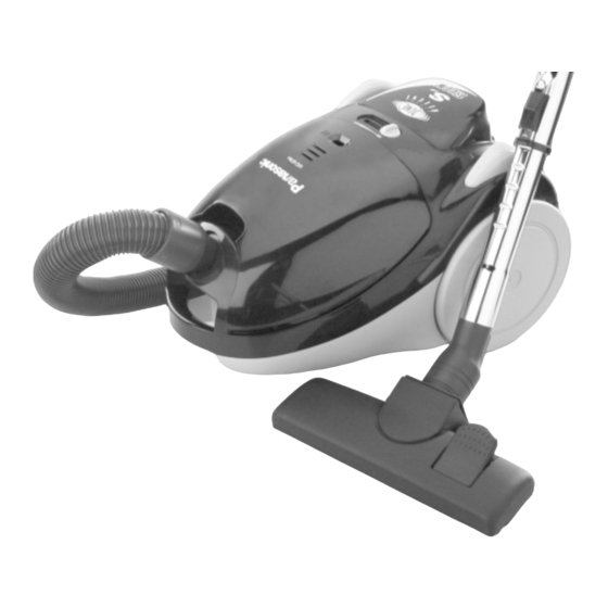
MODELS MC-E780 / MC-E781 / MC-E783
MC-E780
MC-E781
AC230V
AC230V
AC230-240V
AC230-240V
50Hz
50Hz
1500W
1500W
30 kPa
30 kPa
5 m
5 m
7.8 m
7.8 m
6.1 kg
6.1 kg
410x282x255
410x282x255
•
•
•
•
•
•
•
•
MC-E783
AC230V
Depending on version
AC230-240V
50Hz
1500W
30 kPa
5 m
7.8 m
6.1 kg
410x282x255
•
•
•
•
Matsushita Electric España, S.A.
DIVISION DE ASPIRADORAS
Zona Industrial del Polígono de CELRÀ
17460 CELRÀ (Girona) SPAIN
Ref.: Z32T1000
Vacuum Cleaner
Advertisement

Related Manuals for Panasonic MC-E780


Summary of Contents for Panasonic MC-E780
-
Page 1: Vacuum Cleaner
Ref.: Z32T1000 Vacuum Cleaner MODELS MC-E780 / MC-E781 / MC-E783 SPECIFICATIONS MC-E780 MC-E781 MC-E783 Power source AC230V AC230V AC230V Depending on version AC230-240V AC230-240V AC230-240V 50Hz 50Hz 50Hz Input power (max.) 1500W 1500W 1500W Vacuum 30 kPa 30 kPa 30 kPa... -
Page 2: Table Of Contents
..............SCHEMATIC DIAGRAM MC-E780 TRIAC... -
Page 3: Pictorialwiring Diagram
PICTORIALWIRING DIAGRAM MC-E780 Carbon brush holder "S" marked Black MOTOR THERMAL CUT-OUT Yellow Carbon brush holder "P" marked Yellow CORD REEL ON/OFF Black SWITCH White POWER CONTROL CIRCUIT MC-E781 / MC-E783 Carbon brush holder "S" marked Black MOTOR THERMAL CUT-OUT... -
Page 4: Exploded View
EXPLODED VIEW... - Page 5 EXPLODED VIEW...
- Page 6 EXPLODED VIEW...
- Page 7 EXPLODED VIEW...
-
Page 8: Spare Parts List
SPARE PARTS LIST Applied for REF. No. DESCRIPTION PART No. Pcs/Set REMARKS MC-E780 MC-E781 MC-E783 all countries ( ) HOSE UNIT AMC8A92T1034 • • • HOSE AMC8A01K0034 • • • HOSE CONNECTING TUBE AMC8A0281034 • • • CURVED TUBE UNIT AMC8A94P1034 •... - Page 9 SPARE PARTS LIST Applied for REF. No. DESCRIPTION PART No. Pcs/Set REMARKS MC-E780 MC-E781 MC-E783 all countries ( ) EXHAUST COVER (GREEN COLOUR) AMC8T07T10E1 • • EXHAUST COVER (BLUE COLOUR) AMC8T07T10Z4 • • EXHAUST COVER (YELLOW COLOUR) AMC8T07T1093 • EXHAUST COVER (BLAK COLOUR) AMC8T07T3061 •...
-
Page 10: Replacement Of Main Parts
SPARE PARTS LIST Applied for REF. No. DESCRIPTION PART No. Pcs/Set REMARKS MC-E781 MC-E783 MC-E780 all countries ( ) CORD REEL SUPPORT UNIT AMC8P91T1000 • • • Needed a screwdriver type TAPPING SCREW (CORD REEL) XTT4*16C • • • TORK T20 H DUST PAPER BAG (PACK OF 5/PC.) - Page 11 REPLACEMENT OF MAIN PARTS 3. Remove 7 screws from upper body and take out front cover Front cover and upper body. (Fig. 3) Cord reel Switch Pedal Pedal Spring Spring Upper body Lower body Fig. 3 4. Take out cord reel ass’y and remove black and white lead wires (provided with quick-connect terminal) from the contact spring tabs.
- Page 12 Remove (quick- connect terminals) Central motor support (Except mod. MC-E780) Fig. 5 6. Remove 3 screws from motor cover and separate cover A and B. (Fig. 6) 7. Remove noise suppressor and disconnect yellow and black lead wires (provided with quick-connect terminals) from the carbon brush holder tabs.
- Page 13 REPLACEMENT OF MAIN PARTS 8. Remove from the motor rear /front motor supports and noise suppressor. (Fig. 7) Front motor Motor support Rear motor Noise support suppressor Fig. 7 9. Replace the motor with a new one and connect yellow and Motor cover B black lead wires to the carbon brush holder tabs.
- Page 14 REPLACEMENT OF MAIN PARTS (2) Carbon brushes Cut metal end Metal end NOTE: The two carbon brushes should be replaced at the same time. 1. Take out motor unit and remove motor cover A and B as explained previously in paragraph (1) “Motor”, points 1-6. 2.
- Page 15 REPLACEMENT OF MAIN PARTS 3. Remove power control circuit from its fastening points and Fastening points disconnect the lead wires from the power control circuit. (Fig. 15) 4. Replace power control circuit with a new one and connect the lead wires according to the schematic diagram. 5.
- Page 16 REPLACEMENT OF MAIN PARTS 3. Replace the potentiometer with a new one and connect the lead wires (blue and grey) to the potentiometer tabs. 4. Reinstall the potentiometer in its support and reassemble the remaining parts in the reverse order. (Fig. 18) Fig.
- Page 17 REPLACEMENT OF MAIN PARTS (2) Power cord Stopper 1. Remove cord reel unit as explained previously in paragraph (1) “Cord reel unit”, points 1-3. 2. Unwind the total power cord length from the cord reel. 3. Press and release the stopper on the cord reel and lift the contact base by pushing its lower end.
-
Page 18: Trouble Shooting Guide
TROUBLE SHOOTING GUIDE CONDITION CHECKPOINT METHOD OF INSPECTION CAUSE / REMEDY Motor fails to rotate. Power cord Check power cord continuity between If there is no continuity, (no noise is heard connection. plug pins and contact base. replace the power cord. at all). -
Page 19: Packing Instructions
PACKING INSTRUCTIONS...