
Subscribe to Our Youtube Channel
Related Manuals for iPECS iPECS-MG


Summary of Contents for iPECS iPECS-MG
- Page 1 Hardware Description & Installation Manual Please read this manual carefully before operating System. Retain it for future reference...
- Page 2 Issue 1.1 Regulatory Information Before connecting the iPECS-MG to the telephone network, you may be required to notify your local serving telephone company of your intention to use “customer provided equipment”. You may further be required to provide any or all of the following information:...
- Page 3 Hardware Description and Installation Manual Issue 1.1 FCC Interference Statement Note This equipment has been tested and found to comply with the limits for a Class B digital device, pursuant to part 15 of the FCC Rules. These limits are designed to provide reasonable protection against harmful interference in a residential installation.
- Page 4 Hardware Description and Installation Manual Issue 1.1 [USA/CSA] FCC/IC Interference Statement This equipment has been tested and found to comply with the limits for a Class A digital device, pursuant to part 15 of the FCC Rules. These limits are designed to provide reasonable protection against harmful interference when the equipment is operated in a commercial environment.
- Page 5 Hardware Description and Installation Manual Issue 1.1 in a manner that will retain the earth connection when the power supply cord is unplugged. The connection to earth of the supplementary earthing conductor shall be in compliance with the appropriate rules for terminating bonding jumpers in Part K of Article 250 of the National Electrical Code, ANSI/NFPA 70 and Article 10 of Part 1 of the Canadian Electrical Code, Part 1, C22.1.
- Page 6 The information furnished by Ericsson-LG in this material is believed to be accurate and reliable, but is not warranted to be true in all cases. iPECS is trademark of Ericsson-LG Co., Ltd. All other brand and product names are trademarks or registered trademarks of their respective...
-
Page 7: Table Of Contents
1.2.1 Caution ...................... 2 1.2.2 Disposal of Old Appliance ................. 3 1.3 Manual Use ..................3 2. System Overview ..............4 2.1 iPECS-MG System Highlights ............4 2.2 System Connection Diagram ............5 2.3 System Components ..............6 2.4 General Specifications ..............7 2.4.1 Dimension and Weight ................ - Page 8 Hardware Description and Installation Manual Issue 1.1 4.1 BKSU Unpacking ................. 17 4.2 EKSU Unpacking ................. 18 4.3 KSU Diagram, Exterior and Dimension ........19 4.4 Basic KSU Mounting ..............20 4.4.1 Rack Mounting ..................20 4.4.2 Wall Mounting ..................21 4.5 Expansion KSU Installation ............
- Page 9 Hardware Description and Installation Manual Issue 1.1 5.3.4.1 Switch and LED Functions ..............52 5.3.4.2 T1-PRIB Installation ................52 5.3.4.3 T1-PRIB Wiring ..................53 5.3.4.4 Serial Port ..................... 53 5.4 Extension Boards ................ 54 5.4.1 SLIB (Single Line Interface Board w/RJ45) ..........54 5.4.1.1 LED Functions ..................
- Page 10 6.1.5 Wall Mount ....................95 6.1.5.1 LDP-7000 and LIP-7000 Wall Mounting ..........95 6.1.5.2 LIP-8000 & 8000E Wall Mounting ............95 7. STARTING THE IPECS-MG ..........97 7.1 Initializing Databases ..............97 8. TROUBLESHOOTING ............100 9. APPENDIX. USEFUL INFORMATION ........ 102...
-
Page 11: Introduction
Hardware Description and Installation Manual Issue 1.1 1. I NTRODUCTION 1.1 Important Safety Instructions 1.1.1 Safety Requirements When using your telephone equipment, basic safety precautions should always be followed to reduce the risk of fire, electric shock and other personal injury, including the following: ... -
Page 12: Precaution
Keep the system away from heating appliances and electrical noise generating devices such as florescent lamps, motors and televisions. These noise sources can interfere with the performance of the iPECS-MG System. This system should be kept free of dust, moisture, high temperature (more than 40 degrees) and vibration, and should not be exposed to direct sunlight. -
Page 13: Disposal Of Old Appliance
1.3 Manual Use This document provides general information covering the hardware description and installation of the iPECS-MG System. While every effort has been taken to ensure the accuracy of this information Ericsson-LG Co., Ltd. makes no warranty of accuracy or interpretations thereof. -
Page 14: System Overview
Hardware Description and Installation Manual Issue 1.1 2. S YSTEM VERVIEW 2.1 iPECS-MG System Highlights Features of the iPECS-MG System include: Flexible System Capacity and architecture Minimum daughter board Powerful PC application, Remote maintenance via LAN/Modem/RS-232C, Web Admin ... -
Page 15: System Connection Diagram
Hardware Description and Installation Manual Issue 1.1 2.2 System Connection Diagram The following Figure 2.2-1 System Connection Diagram shows the components that make up the iPECS-MG solution: Figure 2.2-1 System Connection Diagram... -
Page 16: System Components
Hardware Description and Installation Manual Issue 1.1 2.3 System Components ITEM OPTION DESCRIPTION BOARD BKSU Basic KSU EKSU Expansion KSU Power Supply Unit (350W) Main Board MPB100 Main Processor Board 100 w/6 DKT, 6 SLT MODU Modem Unit MPB300... -
Page 17: General Specifications
Hardware Description and Installation Manual Issue 1.1 2.4 General Specifications 2.4.1 Dimension and Weight ITEM HEIGHT (mm) WIDTH (mm) DEPTH (mm) WEIGHT (kg) BKSU 170.2 325.4 EKSU 170.2 325.4 6.25 Digital Keyset* Digital DSS/DLS Console Digital ICM/Door Box Digital Data Module Base Station (600B/ 600BE) 0.46... -
Page 18: Psu Fan
Hardware Description and Installation Manual Issue 1.1 2.4.4 PSU Fan ITEM SPECIFICATION Maker / part number POWERLOGIC / PLA07015B05H Dimensions 70 X 70 X 15 (mm) Rated voltage 2.4.5 DECT Base Station (GDC-400B/GDC-600B/GDC-600BE) ITEM SPECIFICATION Power feeding +30V DC Transmission Max. -
Page 19: Co Loop
Hardware Description and Installation Manual Issue 1.1 2.4.7 CO Loop ITEM SPECIFICATION Ring Detect Sensitivity 30Vrms @20–50Hz DTMF Dialing Frequency Deviation Less than +/– 1.8 % Signal Rise Time Max. 5ms Tone Duration, on time Min. 50ms Inter–digit Time Min. -
Page 20: Voip Channels (Voib)
Hardware Description and Installation Manual Issue 1.1 2.4.10 VOIP channels (VOIB) ITEM SPECIFICATION LAN Interface 10 / 100 Base–T Ethernet (IEEE 802.3) Speed 10 Mbps or 100 Mbps (Auto–Negotiation) Duplex Half Duplex or Full Duplex (Auto–Negotiation) VoIP Protocol SIP (RFC3261) and H.323 Revision 2 Voice Compression G.711/G.729/G.723.1... -
Page 21: System Capacity
Hardware Description and Installation Manual Issue 1.1 2.5 System Capacity DESCRIPTION CAPACITY/BOARD TOTAL Time Slots 144 per KSU, Total Max. 432 Max. Ports 200 (MPB100), 414 (MPB300) CO Line Ports 80 (MPB100) , 240 (MPB300) Max. Direct Station (DKT, SLT,... -
Page 22: System Maximum Call Capacity
Hardware Description and Installation Manual Issue 1.1 2.5.1 System Maximum Call Capacity iPECS-MG, MAXIMUM PORT MPB100 EXTENSION TRUNK DKTU/SLT 102*1 Total KSU + 2 Total *1 DSIU DKT 6 + DTIB24, 4ea − Max. DECT Terminal registration : 96 −... - Page 23 Hardware Description and Installation Manual Issue 1.1 *1 DSIU DKT/SLT 6 + (4) DTIB24/SLIB24 *2 DSIU DKT 6 + DSIU SLT 6 + (4) DTIB24/SLIB24 − Max. DECT Terminal registration : 192 − Max. IP Phone registration : 324 −...
-
Page 24: Installation Overview
7. Initial power-up to default the database 8. Configure the system, see iPECS Feature and Admin Manuals 9. Verify the installation. 3.2 Types of Connectors The following chart displays the various types of connectors employed with the iPECS-MG and the various boards. iPECS-MG MATING-CONNECTOR... - Page 25 Hardware Description and Installation Manual Issue 1.1 iPECS-MG MATING-CONNECTOR BOARD PURPOSE CONNECTOR TYPE Serial Port RS–232C Serial to Audio Jack VOIB8, VOIB24, VMIB, Serial Port AAIB PRIB, BRIB2, BRIB4, WTIB4, WTIB8 Audio Jack EXT MOH Port EXT PAGE Port...
-
Page 26: Installation And Safety Precautions
Use caution when installing or modifying telephone lines. Anti-static precautions should be taken during installation. The iPECS-MG System is designed for wall mounting or a freestanding rack. Avoid installing in the following places: In direct sunlight and extremely hot, cold, or humid places (optimal temperature range = 0o to 40oC). -
Page 27: Ksu Installation
Hardware Description and Installation Manual Issue 1.1 4. KSU I NSTALLATION 4.1 BKSU Unpacking Open the box and verify the items shown in Figure 4.1-1 BKSU Carton Contents are included: Figure 4.1-1 BKSU Carton Contents... -
Page 28: Eksu Unpacking
Hardware Description and Installation Manual Issue 1.1 4.2 EKSU Unpacking Open the box and verify the items shown in Figure 4.2-1 EKSU Carton Contents are included: Figure 4.2-1 EKSU Carton Contents... -
Page 29: Ksu Diagram, Exterior And Dimension
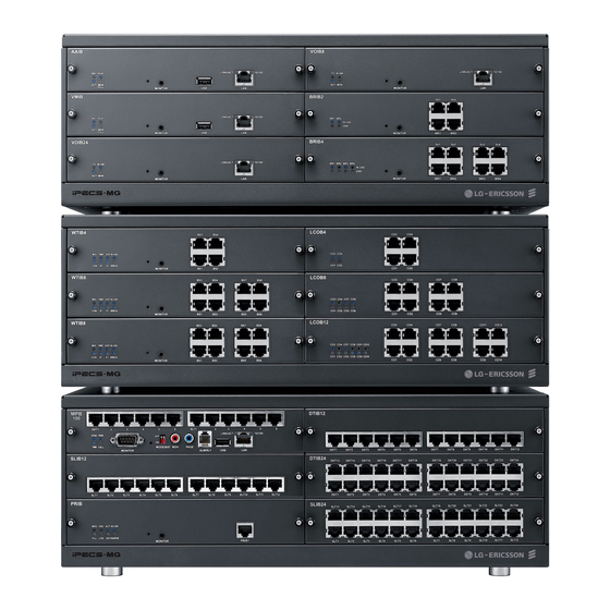
Hardware Description and Installation Manual Issue 1.1 4.3 KSU Diagram, Exterior and Dimension For reference purposes, Figure 4.3-1 shows the exterior and dimensions of the KSU. Figure 4.3-1 KSU Exterior and Dimension... -
Page 30: Basic Ksu Mounting
Hardware Description and Installation Manual Issue 1.1 4.4 Basic KSU Mounting The KSU can be 19” rack or wall mounted. 4.4.1 Rack Mounting 1. Install the Rack Mount brackets to each side of the KSU with the eight (8) screws provided. -
Page 31: Wall Mounting
Hardware Description and Installation Manual Issue 1.1 4.4.2 Wall Mounting 1. Attach the included mounting template for accurate placement to the wall, level, and drill 12 holes. 2. Install 12 anchor plugs into the wall using the mounting template (Figure 4.4.2 1 Wall Mounting). - Page 32 Hardware Description and Installation Manual Issue 1.1 Figure 4.4.2-1 Wall Mounting...
-
Page 33: Expansion Ksu Installation
Hardware Description and Installation Manual Issue 1.1 4.5 Expansion KSU Installation The Expansion KSU is installed on top of the Basic KSU. Fasteners are installed on each side of the KSUs to maintain a stable mechanical connection. The Expansion cable is installed to connect the KSU backplane signaling and media (voice) paths. - Page 34 Hardware Description and Installation Manual Issue 1.1 C9 connector C8 connector Figure 4.5-1 Expansion KSU installation Figure4.5-2 Expansion KSU Wall Mounting...
- Page 35 Hardware Description and Installation Manual Issue 1.1 Figure 4.5-3 Expansion KSU Rack Mounting...
-
Page 36: Power Supply Unit Wiring
The 1st KSU will work independent of the 2nd KSU (powered-Off); however, the 3rd KSU cannot work without the 2nd KSU powered-On. It is recommended that the iPECS-MG be reset if the PSU in an EKSU is power cycled or turned OFF. -
Page 37: External Backup Battery Installation
4.6.2 External Backup Battery Installation In case of power failure, the external backup batteries automatically maintain uninterrupted power for the iPECS-MG System. The external batteries must provide 24V DC; this is generally accomplished by connecting two 12V batteries in a series arrangement as shown: ... -
Page 38: Power Supply Unit Replacement
Using the PSU handle pull the PSU from the KSU. To install the new PSU Insert the PSU along the guide rails on the rear side of iPECS-MG. Slide PSU into the KSU to firmly seat the PSU in the backplane connector ... - Page 39 The 1st KSU will work independent of the 2nd KSU (powered OFF); however, the 3rd KSU cannot work without the 2nd KSU powered-ON. It is recommended that the iPECS-MG be reset if the PSU to an EKSU is power cycled or turned OFF.
-
Page 40: Board Installation
Hardware Description and Installation Manual Issue 1.1 5. BOARD INSTALLATION 5.1 General Board Install Procedure Prior to installing the Boards, the following should be considered: CAUTION Verify the electrical Power is turned OFF before installation of boards. To protect the System from static electricity, do not directly touch the boards to discharge static, touch a grounded object, or wear a grounding strap. -
Page 41: Main Processing Board
Hardware Description and Installation Manual Issue 1.1 5.2 Main Processing Board The Main Processor Board controls communication between the peripheral boards, supervises all resources in the system, controls the gain adjustment of the PCM signal, generates the System tones, maintains System audio prompts and manages System call processing. The MPB (Figure 5.2 1) is the main control for the System, and is composed of the microprocessor... -
Page 42: Switch And Led Functions
Hardware Description and Installation Manual Issue 1.1 4 Status Indication LEDs 1 RS-232C serial port 1 Reset Button 1 Switch for Admin Database back up 1 External MOH port 1 External Paging port ... - Page 43 LD3 (Blue), SYNC External ISDN board (PRI or BRI) Clock synchronization ON: PLL circuit activation by External Clock from ISDN Board, iPECS-MG will be operated based on external ISDN clock (refer to “NOTE”). OFF: PLL activation by Internal Clock, iPECS-MG will be operated based on internal clock.
-
Page 44: Modem Unit Installation
CO line by calling the Modem CO line or Station. For additional information on MODU set-up, see the iPECS-MG Admin Manual. The MODU is installed on connectors CN4 and CN5 of the MPB as shown in Figure 5.2-1. Use care to align pins of the CN4 and CN 5 connector with the CN1 and CN2 connectors on the MODU and press firmly in place. -
Page 45: Connecting Miscellaneous Devices
Hardware Description and Installation Manual Issue 1.1 5.2.5 Connecting Miscellaneous Devices The MPB provides connections for an external music source, an external page port, a relay contact, and an alarm detection input monitor. Figure 5.2.5-1 Miscellaneous Connections 5.2.5.1 Alarm/Relay Wiring The RJ-11 Alm/Rly connector provides access to the Remote Contact Monitoring circuitry and an External Control Contact. -
Page 46: Page Audio Connector Wiring
The USB connector is provided to allow a USB memory stick to connect to the system for upload and download of the System database. No wiring of the USB connector is required. For further information on operation of the USB port, refer to the iPECS-MG Admin Manual. Table 5.2.6-1 USB Connector... -
Page 47: Monitor Wiring
Referring to the pin-out chart above and the wiring diagram below, wire the RS-232 port to an appropriate DTE (Data Terminal Equipment), tag or number wiring for maintenance LIK MODULE TYPICAL TERMINAL iPECS-MG DB- LIP-8000 DB-9 RS-232 DB-9 RS-232 TERMINATIONS TERMINATIONS 9 RS-232... -
Page 48: Dsiu (Digital And Single Line Interface Unit) Wiring
Hardware Description and Installation Manual Issue 1.1 5.2.8 DSIU (Digital and Single Line Interface Unit) Wiring The DSIU is included on the MPB and provides six (6) Digital Terminal (DKT-1 to 6) ports and six (6) Single Line (SLT 1 to 6) ports. The DSIU SLT ports support FSK (ITU-T V.23 or Bell 202) or DTMF (ITU-T Q.23) Caller ID to the SLT. -
Page 49: Co Line Boards
The iPECS-MG LCOB (Loop Start CO Interface Board) is employed to interface standard analog PSTN CO lines to the iPECS-MG system. The LCOB is available in three models, the LCOB4 with 4 analog CO ports, the LCOB8 with 8 ports, and the LCOB12 with 12 ports. The LCOB supports Caller Identification (CID) detection, Polarity Reversal (PR) detection and Call Progress Tone (CPT) detection. -
Page 50: Cmu (Call Metering Unit) Installation
An optional CMU4 board, which supports four (4) LCOB ports each, is required to support call- metering service (50Hz, 12 kHz, and 16 kHz). For additional information on CMU, see the iPECS-MG Feature Manual. Install a CMU4 on connector pairs CN1 and 2, CN3 and 4, and CN5 and 6 on the LCOB to support CO Line ports 1 and 12, as shown in Figure 5.3.1 1. -
Page 51: Lcob Wiring
Hardware Description and Installation Manual Issue 1.1 5.3.1.3 LCOB Wiring The CO Line Tip and Ring terminations are located on the center pair of each RJ45 connector. A separate RJ45 is provided for each analog CO Line supported by the LCOB (4, 8, or 12). -
Page 52: Brib (Basic Rate Interface Board) W/Selectable S/T Interface
Hardware Description and Installation Manual Issue 1.1 5.3.2 BRIB (Basic Rate Interface Board) w/Selectable S/T Interface There are two kinds of BRIB2/BRIB4 according to CPU, but they have the same functions. The BRIB is available in two models, the BRIB2 with two (2) BRI lines (4 channels) and the BRIB4 with four (4) BRI lines (8 channels). - Page 53 Hardware Description and Installation Manual Issue 1.1 Figure 5.3.2-1 BRIB2 and BRIB4 Note iPECS-MG does not support daisy chained clocking for digital lines. The clock priority and synchronization is controlled by Admin. For details, refer to PGM 301 of the iPECS- MG Admin Manual.
-
Page 54: Switch And Led Functions
Hardware Description and Installation Manual Issue 1.1 The default clock is assigned based on the board type, KSU, and slot as below. − Board – PRIB > BRIB2/BRIB4 > Internal Clock − KSU – 1’st KSU > 2’nd KSU > 3’rd KSU −... - Page 55 Hardware Description and Installation Manual Issue 1.1 Table 5.3.2.1-3 BRIB Power Feed SWITCH FUNCTION SW7-1 Line 1 Power Feed (-40V) Feed Open SW7-2 Feed Open Line 1 Power Feed (Ground) SW9-1 Line 2 Power Feed (-40V) Feed Open SW9-2...
-
Page 56: Brib Installation
Hardware Description and Installation Manual Issue 1.1 5.3.2.2 BRIB Installation Before installation of the BRIB, set the Mode, Terminating Resistor, and Power Feed Switches for each BRIB Line. Note that the BRIB cannot simultaneously support both the T and S mode, all ports on the BRIB must be set in the same mode, T or S. -
Page 57: Serial Port
Hardware Description and Installation Manual Issue 1.1 Table 5.3.2.3-1 RJ45 NAME NAME CONECTOR FUNCTION FUNCTION (T-mode) (S-mode) RJ45 1,2,7,8 Reserved Transmit Data Receive Data Receive Data Transmit Data Receive Data Transmit Data Transmit Data Receive Data Figure 5.3.2.3-1 ISDN Connections (Basic Rate) 5.3.2.4 Serial Port... -
Page 58: E1R2-Prib (Primary Rate Interface Board)
Hardware Description and Installation Manual Issue 1.1 5.3.3 E1R2-PRIB (Primary Rate Interface Board) There are two kinds of PRIB according to CPU, but they have the same functions. The Primary Rate Interface Board (PRIB) provides one (1) PRI interface, or one (1) E1R2 interface. -
Page 59: Switch And Led Functions
NOTE iPECS-MG does not support daisy chained clocking for digital lines. The clock priority and synchronization is controlled by Admin. For details, refer to PGM 301 of the iPECS- MG Admin Manual. The default clock is assigned based on the board type, KSU, and slot as below. -
Page 60: E1-Prib Wiring
Hardware Description and Installation Manual Issue 1.1 Assure Power is OFF Slide the PRIB in the guide rails of the desired slot. Tighten thumbscrews to hold the board firmly in place. 5.3.3.3 E1-PRIB Wiring The E1-PRIB Transmit and Receive pairs are terminated in the PRI/E1 RJ45 connector. A single RJ45 is provided for the digital line interface. -
Page 61: T1-Prib (Primary Rate Interface Board)
Hardware Description and Installation Manual Issue 1.1 5.3.4 T1-PRIB (Primary Rate Interface Board) There are two kinds of PRIB according to CPU, but they have the same functions. The T1 and Primary Rate Interface (PRI) board interfaces to North American standards based digital networks. -
Page 62: Switch And Led Functions
NOTE iPECS-MG does not support daisy chained clocking for digital lines. The clock priority and synchronization is controlled by Admin. For details, refer to PGM 301 of the iPECS- MG Admin Manual. The default clock is assigned based on the board type, KSU, and slot as below. -
Page 63: T1-Prib Wiring
Hardware Description and Installation Manual Issue 1.1 5.3.4.3 T1-PRIB Wiring The T1-PRIB Transmit and Receive pairs are terminated in the PRI/T1 RJ45 connector. A single RJ45 is provided for the digital line interface. Before wiring the PRIB, the Ferrite core provided with the T1-PRIB must be installed to reduce EMI (Elector-Magnetic Interference). -
Page 64: Extension Boards
Hardware Description and Installation Manual Issue 1.1 5.4 Extension Boards 5.4.1 SLIB (Single Line Interface Board w/RJ45) There are two kinds of SLIB12/SLIB24 according to CPU, but they have the same functions. The SLIB is available in two (2) models, the SLIB 12 with 12 analog Single Line Telephone ports and the SLIB24 with 24 SLT ports. -
Page 65: Led Functions
Hardware Description and Installation Manual Issue 1.1 Figure 5.4.1-1 SLIB12/24 5.4.1.1 LED Functions FUNCTION REMARK ACT, Activation or Normal Operating Blink (Blue Color) ON: one or ports in use IN USE OFF: All channels, Idle 5.4.1.2 SLIB Installation The SLIB has no switches or connectors that are field useable. The SLIB can be installed in any universal slot of any KSU;... -
Page 66: Slib Wiring
Hardware Description and Installation Manual Issue 1.1 5.4.1.3 SLIB Wiring The SLT is terminated to the center pair of each RJ45 connector. A separate RJ45 is provided for each SLT port on the SLIB (12 or 24 connectors). Referring to the pin-out chart below, ... -
Page 67: Slibc (Single Line Interface Board W/Rj21)
Hardware Description and Installation Manual Issue 1.1 5.4.2 SLIBC (Single Line Interface Board w/RJ21) There are two kinds of SLIB12C/SLIB24C according to CPU, but they have the same functions. The SLIBC is available in two (2) models, the SLIB12C with 12 SLT ports and the SLIB24C with 24 SLT ports. - Page 68 Hardware Description and Installation Manual Issue 1.1 Figure 5.4.2-1 SLIB12/24C...
-
Page 69: Led Functions
Hardware Description and Installation Manual Issue 1.1 5.4.2.1 LED Functions Table 5.4.2.1-1 LED Indications FUNCTION REMARK ON (Blue) : 1 port in use ON (Yellow Green) : 13 port in use The status of 1 port or 13 port... -
Page 70: Slibc Installation
Hardware Description and Installation Manual Issue 1.1 Table 5.4.2.1-1 LED Indications FUNCTION REMARK ON (Blue) : 11 port Use ON (Yellow Green) : 23 port in use LD11 The status of 11 port or 23 port ON (Blush white) : 11... - Page 71 Hardware Description and Installation Manual Issue 1.1 Table 5.4.2.1-2 SLIBC Pin-Out Chart CONNECTOR COLOR CODE SLIB PORT RJ21...
-
Page 72: Dtib (Digital Terminal Interface Board W/Rj-45)
Hardware Description and Installation Manual Issue 1.1 5.4.3 DTIB (Digital Terminal Interface Board w/RJ-45) The DTIB is available in two (2) models, the DTIB12 with 12 Digital Key Telephone Interface ports and the DTIB24 with 24 DKT ports. Each port provides power and signaling to the DKT over a single wire pair. -
Page 73: Led Functions
Hardware Description and Installation Manual Issue 1.1 5.4.3.1 LED Functions Table 5.4.5.1-1 LED Indication FUNCTIONS REMARK ON: Channel in use, IN USE OFF: All channels Idle ACT, Activation or Normal Operating Blink (Blue Color) 5.4.3.2 DTIB Installation The DTIB has no switches or connectors that are field useable. The DTIB can be installed in any universal slot of any KSU;... -
Page 74: Dtibc (Digital Telephone Interface Board W/Rj21 Connector)
Hardware Description and Installation Manual Issue 1.1 5.4.4 DTIBC (Digital Telephone Interface Board w/RJ21 connector) The DTIBC is available in two (2) models, the DTIB12 with 12 Digital Key Telephone Interface ports and the DTIB24 with 24 DKT ports. The DTIBC is identical to the DTIB except the DKT ports of the DTIBC are terminated to an RJ21 connector. -
Page 75: Led Functions
Hardware Description and Installation Manual Issue 1.1 5.4.4.1 LED Functions Table 5.4.6.1-1 LED Indication FUNCTION REMARK ON (Blue) : 1 port Use ON (Yellow Green) : 13 port Use The status of 1 port or 13 port ON (Blush white) : 1... -
Page 76: Dtibc Installation
Hardware Description and Installation Manual Issue 1.1 Table 5.4.6.1-1 LED Indication FUNCTION REMARK ON (Blue) : 11 port Use ON (Yellow Green) : 23 port Use LD11 The status of 11 port or 23 port ON (Blush white) : 11... - Page 77 Hardware Description and Installation Manual Issue 1.1 Table 5.4.6.4-1 DTIBC Pin-out Chart CONNECTOR COLOR CODE SLIB PORT RJ21...
-
Page 78: Wtib (Wireless Telephone Interface Board) For Dect
Issue 1.1 5.4.5 WTIB (Wireless Telephone Interface Board) for DECT The WTIB is the iPECS-MG interface to the System DECT solution for in-building mobility with transparent handover. The WTIB supports European DECT and is not intended for use in other regions. - Page 79 Base Stations and other resources and features of the iPECS-MG. The iPECS-MG100 supports two (2) WTIBs and the iPECS-MG300 will support three (3) WTIBs. Each port on the WTIB terminates to an RJ45 connector on the front panel of the board.
- Page 80 Hardware Description and Installation Manual Issue 1.1 Figure 5.4.5-2 WTIB (Wireless Telephone Interface Board)
-
Page 81: Connectors, Switch And Led Functions
Hardware Description and Installation Manual Issue 1.1 5.4.5.1 Connectors, Switch and LED Functions The following Table shows the relation between the front panel RJ45 connectors and associated Base Station (cell) numbers. Table 5.4.5.1-1 WTIB RJ45 Connector Functions CONNECTOR CELL NUMBER... -
Page 82: Dect Installation
5.4.5.2 DECT Installation For detailed instructions on Site Planning for Base Stations, Cell-coverage Region Survey, RSSI Monitoring, and Base Station Installation, refer to the DECT Installation Guide for iPECS- 5.4.5.3 WTIB Installation Prior to installation, assure the Dipswitch settings are in the default position, section 5.4.5.1. -
Page 83: Wtib Wiring
Hardware Description and Installation Manual Issue 1.1 5.4.5.5 WTIB Wiring Each Base Station port on the WTIB is terminated to an RJ45 connector wired as shown in the pin-out chart below. Separate wiring is required for the TX and RX pairs. Power is delivered from the WTIB to the Base Station over the simplex circuit formed by the TX and RX pairs. -
Page 84: Serial Port
Hardware Description and Installation Manual Issue 1.1 Figure 5.4.5.5-1 WTIB Connection to Multiple System DECT Base Stations 5.4.5.6 Serial Port The VMIB an AAIB include an Audio jack connected to a Serial port. The serial port is used for... -
Page 85: Function Boards
(8) simultaneous channels. For additional channels and/or storage capacity, two (2) VMIBs or AAIBs may be installed in the iPECS-MG100 (16 total channels) and up to three (3) VMIBs or AAIBs may be installed in the iPECS-MG 300 (24 total channels). -
Page 86: Switch, And Led Functions
The VMIB and AAIB have no switches or connectors that are field useable. The VMIB and AAIB can be installed in any universal slot of any KSU; the 1st slot of the BKSU is for the MPB only. A maximum of two boards may be installed in the iPECS-MG100 and three (3) in the iPECS-MG300. -
Page 87: Vmib And Aaib Lan Connector
Hardware Description and Installation Manual Issue 1.1 5.5.1.4 VMIB and AAIB LAN Connector The VMIB and AAIB include an RJ45 for connection to a 10/100 Base-T Ethernet (IEEE 802.3) connection. The port supports auto negotiation for speed (10 or 100 Mbps) and full or half- duplex operation. -
Page 88: Voib (Voice Over Internet Protocol Board, 8 And 24Channel)
VOIB8 and VOIB24. The VOIB provides the Ethernet interface for Ericsson-LG IP Phones, SIP phones and trunks, IP Networking and applications. The VOIB is used to provide packet relay for remote devices to communicate with the host and translate between the iPECS proprietary protocols and other standard protocols (H323 rev.4, SIP RFC3261). -
Page 89: Voib Installation
Hardware Description and Installation Manual Issue 1.1 Table 5.5.2.1-2 LED Indication FUNCTION REMARK VOIB Task Active (CMD/Event Processing) Blink (Blue Color) Trace Task Active (Line Monitor) Blink (Blue Color) On: Transcoding in use Transcoding Off – Transcoding not in use... -
Page 90: Serial To Audio Cable Specification
Hardware Description and Installation Manual Issue 1.1 5.6 Serial to Audio Cable Specification Several board types include a serial port presented as an Audio jack. This serial port is not required for normal operation, it is only used for advanced diagnostics. Boards that include the Audio Serial connector are PRIB, BRIB2/ BRIB4, AAIB/VMIB, VOIB, and WTIB. -
Page 91: Cable Dressing
Hardware Description and Installation Manual Issue 1.1 5.7 Cable Dressing To provide a neat professional installation, the wiring to the KSU(s) should be dressed. The wiring cables should be bundled and tie wrapped to the KSU(s) and to the wall or rack. -
Page 92: Rack Mount Wiring
Hardware Description and Installation Manual Issue 1.1 5.7.2 Rack Mount Wiring To dress wiring for a Rack mount installation, 1. Ensure all boards are installed and that wiring is complete. 2. Using the supplied Cable Ties, tie all wiring cables and Power cord (if desired) together in a neat bundle. -
Page 93: Terminal Connection And Wiring
WIRING 6.1 Terminal and Door Phone Models Various types of digital terminals and IP Terminals can be used with the iPECS-MG as listed in the table and shown below. Other older model digital phones may also be compatible with the iPECS-MG, check with your local Ericsson-LG representative for details. - Page 94 Hardware Description and Installation Manual Issue 1.1 MODEL DESCRIPTION LDP-9008D 8 Flexible Button w/Display LDP-9030D 30 Flexible Button w/Display LDP-9048DSS 48 Button DSS Console LIP-8002E/2AE LIP-8008E LIP-8012E LIP-8024E LIP-8040E Figure 6.1-1 LIP 8000E Series Keysets...
- Page 95 Hardware Description and Installation Manual Issue 1.1 LIP-8002 LIP-8004 LIP-8008D LIP-8050V Figure 6.1-2 LIP-8000 Series Keysets...
- Page 96 Hardware Description and Installation Manual Issue 1.1 LIP-8048LSS Figure 6.1-3 LIP-8000 Series DSS & LSS LD-9008D LD-9030D LD-9048SS Figure 6.1-4 LDP-9000 Series Keysets...
-
Page 97: Terminal Cabling Distance
Hardware Description and Installation Manual Issue 1.1 6.1.1 Terminal Cabling Distance Figure 6.1.1-1 Terminal Cabling Distance 6.1.2 Terminal Connections 6.1.2.1 DKT Wiring The Digital Key Telephone and digital DSS Console are terminated to the 1st pair of the RJ11 located in the bottom of the DKT or Console. -
Page 98: Slt Wiring
6.1.2.3 LIP-7000 & LIP-8000 & 8000E Series Keyset Wiring The iPECS-MG supports the LIP-7000 and 8000 series IP Phones. The LIP-7008D and the LIP-8004D have a single LAN port that is wired to an Ethernet switch port. All other LIP-7000 and 8000 &... -
Page 99: Ldp Door Phone Box
Receive Data 6.1.3 LDP Door Phone Box The iPECS-MG supports the LDP DPB, digital Door Phone Box. The Door Phone Box can place a call to assigned stations and a station can answer the Door Phone Box call. If configured, the station user can activate a door-lock release mechanism to allow entry. - Page 100 Hardware Description and Installation Manual Issue 1.1 Figure 6.1.3.2-1 Door Phone Box Wiring Table 6.1.3.2-1 LDP-DPB Pin-out Chart Line Cord CONNECTOR SIGNAL NAME RJ11 Not used Ring Not used...
-
Page 101: Dss/Blf Console Installation & Wiring
Hardware Description and Installation Manual Issue 1.1 6.1.4 DSS/BLF Console Installation & Wiring 6.1.4.1 LDP-7048 DSS Install The digital LDP-7048 DSS/BLF Console is provided with a phone-mounting bracket, used to fasten the Console to the phone securely. To attach the fastener, ... - Page 102 Hardware Description and Installation Manual Issue 1.1 Referring to install an LIP-8000 series DSS Console, turn the LIP phone and DSS Console upside down remove the rubber plug in the LIP phone protecting the DSS serial cable connector.
- Page 103 Hardware Description and Installation Manual Issue 1.1 Figure 6.1.4-1 LIP-8000 DSS Installation (12DSS + 48DSS) Figure 6.1.4-2 LIP-8000 DSS Installation (12DSS + 12LSS)
- Page 104 Hardware Description and Installation Manual Issue 1.1 Figure 6.1.4-3 LIP-8000 DSS Installation (12DSS + 12LSS+48DSS)
-
Page 105: Wall Mount
Hardware Description and Installation Manual Issue 1.1 6.1.5 Wall Mount 6.1.5.1 LDP-7000 and LIP-7000 Wall Mounting The LDP-7000 or LIP 7000 series phones can be mounted on the wall using the appropriate Wall Mount Kit. The Wall Mount Kit is installed as described below and shown in Figure 6.1.5.1- ... - Page 106 Hardware Description and Installation Manual Issue 1.1 Remove the Handset hook from the phone as shown in the figures below. Reverse the hook and re-install in the LIP-8000 & 8000E phone so that the hook catches the groove in the handset receiver.
-
Page 107: Starting The Ipecs-Mg
7. STARTING THE IPECS-MG 7.1 Initializing Databases After completing installation, it is highly recommended that the iPECS-MG System database be initialized to default values for the local Country Code. During the initialization sequence, the System will identify all the installed resources and assigns port numbers to the each port on each board based on the order of appearance starting at the 1st DKT port on the MPB DSIU then the SLT ports 1 to 6 of the DSIU. - Page 108 If the Country Code is correct, press the On/Off or Speaker button and change the Mode switch to ON. The System is now ready for programming; refer to the iPECS- MG Admin Manuals. If the Country Code is not correct, ...
- Page 109 MPB mode switch to the ON position. With initialization complete, the iPECS-MG can be configured to meet the needs of the business and individual user. For detailed information on programming the iPECS-MG, refer to the iPECS-...
-
Page 110: Troubleshooting
Hardware Description and Installation Manual Issue 1.1 8. TROUBLESHOOTING PROBLEM CAUSE/SYMPTOM SOLUTION System power AC Power Fail Assure Fuse/Breaker is operational. failure Assure AC Power is delivered to AC outlet. Check the PSU Fuse Check LD21, LD22 on the backplane, if out, replace the PSU. - Page 111 Hardware Description and Installation Manual Issue 1.1 PROBLEM CAUSE/SYMPTOM SOLUTION Assure the wiring is not run near equipment that generates high RF interference. Induced noise on the wire between Noise on External the System and the amplifier Assure there are no coils in the wiring.
-
Page 112: Appendix. Useful Information
Hardware Description and Installation Manual Issue 1.1 9. APPENDIX. USEFUL INFORMATION Open Source Software Notice This following GPL (General Public License) software used in this product are subject to the GPL License Agreements. You can obtain a copy of the GPL licenses from Ericsson-LG Web Site (http://www.ericssonlg.com).
Need help?
Do you have a question about the iPECS-MG and is the answer not in the manual?
Questions and answers