
Related Manuals for BeagleBone Black

Summary of Contents for BeagleBone Black
- Page 1 BeagleBone Black System REF: BBONEBLK_SRM Rev A5.2 Reference Manual BeagleBone Black System Reference Manual Revision A5.2 April 11, 2013 Author: Gerald Coley Contributing Editor: Robert P J Day Page 1 of 108...
- Page 2 BeagleBone Black System REF: BBONEBLK_SRM Rev A5.2 Reference Manual THIS DOCUMENT This work is licensed under the Creative Commons Attribution-Share Alike 3.0 Unported License. To view a copy of this license, visit http://creativecommons.org/licenses/by- sa/3.0/ or send a letter to Creative Commons, 171 Second Street, Suite 300, San Francisco, California, 94105, USA.
- Page 3 BeagleBone Black System REF: BBONEBLK_SRM Rev A5.2 Reference Manual BEAGLEBONE DESIGN These design materials referred to in this document are *NOT SUPPORTED* and DO NOT constitute a reference design. Only “community” support is allowed via resources at BeagleBoard.org/discuss. THERE IS NO WARRANTY FOR THE DESIGN MATERIALS, TO THE EXTENT PERMITTED BY APPLICABLE LAW.
- Page 4 Should the BeagleBone not meet the specifications indicated in the System Reference Manual, the BeagleBone may be returned within 90 days from the date of delivery to the distributor of purchase for a full refund. THE FOREGOING LIMITED WARRANTY IS THE...
- Page 5 Suppliers, its licensors and their representatives harmless from and against any and all claims, damages, losses, expenses, costs and liabilities (collectively, "Claims") arising out of or in connection with any use of the BeagleBone that is not in Page 5 of 108...
- Page 6 Reference Manual accordance with the terms of the agreement. This obligation shall apply whether Claims arise under law of tort or contract or any other legal theory, and even if the BeagleBone fails to perform as described or expected. Safety-Critical or Life-Critical Applications. If you intend to evaluate the components for possible use in safety critical applications (such as life support) where a failure of the Supplier’s product...
-
Page 7: Table Of Contents
INTRODUCTION..........................12 CHANGE HISTORY .........................12 ......................12 OCUMENT HANGE ISTORY ..........................12 OARD HANGES 2.2.1 Rev A5B ..........................12 CONNECTING UP YOUR BEAGLEBONE BLACK ..............13 ’ ........................13 N THE .......................14 ONNECTION CENARIOS A PC .........................14 ETHERED 3.3.1 Connect the Cable to the Board .....................15 3.3.2... - Page 8 BeagleBone Black System REF: BBONEBLK_SRM Rev A5.2 Reference Manual 6.1.3 USB Power ..........................39 6.1.4 Power Selection ........................39 6.1.5 Power Button .........................40 6.1.6 Battery Access Pads .......................40 6.1.7 Power Consumption ......................41 6.1.8 Processor Interfaces ......................41 6.1.9 Power Rails ...........................43 6.1.10 Power LED ........................46 6.1.11...
-
Page 9: Figures
8.4.1 Non-Stacking Headers-Single Cape ..................93 8.4.2 Main Expansion Headers-Stacking ..................94 8.4.3 Stacked Capes w/Signal Stealing ...................95 8.4.4 Retention Force ........................96 8.4.5 BeagleBone Black Female Connectors ..................96 ..........................97 IGNAL SAGE ............................97 OWER 8.6.1 Main Board Power ........................97 8.6.2 Expansion Board External Power ..................98 ...........................98... - Page 10 Figure 17. Connectors, LEDs and Switches ............... 27 Figure 18. Key Components ..................28 Figure 19. BeagleBone Black Key Components ............29 Figure 20. BeagleBone Black Block Diagram ............35 Figure 21. High Level Power Block Diagram ............36 Figure 22.
-
Page 11: Tables
Tables Table 1. Change History ..................... 12 Table 2. BeagleBone Black Features ................26 Table 3. BeagleBone Black Battery Pins ..............40 Table 4. BeagleBone Black Power Consumption(mA@5V) ........41 Table 5. Processor Features ..................49 Table 6. eMMC Boot Pins ..................54 Table 7. -
Page 12: Ref: Bboneblk_Srm
The board will primarily be referred to in the remainder of this document simply as the board, although it may also be referred to as the BeagleBone Black as a reminder. There are also references to the original BeagleBone as well, and will be referenced as simply BeagleBone. -
Page 13: Connecting Up Your Beaglebone Black
BeagleBone Black System REF: BBONEBLK_SRM Rev A5.2 Reference Manual Connecting Up Your BeagleBone Black This section provides instructions on how to hook up your board. Two scenarios will be discussed: 1) Tethered to a PC and 2) As a standalone development platform in a desktop PC configuration. -
Page 14: Main Connection Scenarios
BeagleBone Black System REF: BBONEBLK_SRM Rev A5.2 Reference Manual Main Connection Scenarios This section will describe how to connect the board for use. This section is basically a slightly more detailed description of the Quick Start Guide that came in the box. There is also a Quick Start Guide document on the board that should also be refereed. -
Page 15: Connect The Cable To The Board
BeagleBone Black System REF: BBONEBLK_SRM Rev A5.2 Reference Manual All the power for the board is provided by the PC via the USB cable. In some instances, the PC may not be able to supply sufficient power for the board. In that case, an external 5VDC power supply can be used, but this should rarely be necessary. -
Page 16: Accessing The Board As A Storage Drive
BeagleBone Black System REF: BBONEBLK_SRM Rev A5.2 Reference Manual 4. When the board starts to boot the LEDs will come on in sequence as shown in Figure 5 below. It will take a few seconds for the status LEDs to come on, so be patient. -
Page 17: Standalone W/Display And Keyboard/Mouse
BeagleBone Black System REF: BBONEBLK_SRM Rev A5.2 Reference Manual Standalone w/Display and Keyboard/Mouse In this configuration, the board works more like a PC, totally free from any connection to a PC as shown in Figure 6. It allows you to create your code to make the board do whatever you need it to do. -
Page 18: Connecting Up The Board
BeagleBone Black System REF: BBONEBLK_SRM Rev A5.2 Reference Manual For an up-to-date list of confirmed working accessories please go to http://circuitco.com/support/index.php?title=BeagleBone_Black_Accessories 3.4.2 Connecting Up the Board 1. Connect the big end of the HDMI cable as shown in Figure 7 to your HDMI monitor. -
Page 19: Figure 9. Wireless Keyboard And Mouse Combo
BeagleBone Black System REF: BBONEBLK_SRM Rev A5.2 Reference Manual 3. If you have a single wireless keyboard and mouse combination such as seen in Figure 9 below, you need to plug the receiver in the USB host port of the board as shown in Figure 10. -
Page 20: Apply Power
BeagleBone Black System REF: BBONEBLK_SRM Rev A5.2 Reference Manual If you decide you want to connect to your local area network, an Ethernet cable can be used. Connect the Ethernet Cable to the Ethernet port as shown in Figure 12. Any standard 100M Ethernet cable should work. -
Page 21: Figure 14. Connect Microhdmi Cable To The Board
BeagleBone Black System REF: BBONEBLK_SRM Rev A5.2 Reference Manual 6. The cable needed to connect to your display is a microHDMI to HDMI. Connect the microHDMI connector end to the board at this time. The connector is on the bottom side of the board as shown in Figure 14 below. -
Page 22: Figure 15. Board Boot Status
BeagleBone Black System REF: BBONEBLK_SRM Rev A5.2 Reference Manual Figure 15. Board Boot Status While the four user LEDS can be over written and used as desired, they do have specific meanings in the image that is shipped with the board once the Linux kernel has booted. -
Page 23: Figure 16. Desktop Screen
BeagleBone Black System REF: BBONEBLK_SRM Rev A5.2 Reference Manual Figure 16. Desktop Screen NOTE: At press time this is what the default screen looks like. If you see something different, do not be alarmed. It is intended. Once the final screen is finalized, this document will be updated and available for download. -
Page 24: Beaglebone Black Overview
BeagleBone Black via onboard support of some interfaces. It is not a complete product designed to do any particular function. It is a foundation for experimentation and learning how to program the processor and to access the peripherals by the creation of your own software and hardware. -
Page 25: Beaglebone Compatibility
Reference Manual BeagleBone Compatibility The board is intended to be compatible with the original BeagleBone as much as possible. There are several areas where there are differences between the two designs. These differences are listed below, along with the reasons for the differences. -
Page 26: Beaglebone Black Features And Specification
REF: BBONEBLK_SRM Rev A5.2 Reference Manual BeagleBone Black Features and Specification This section covers the specifications and features of the board and provides a high level description of the major components and interfaces that make up the board. Table 2 provides a list of the features. -
Page 27: Board Component Locations
BeagleBone Black System REF: BBONEBLK_SRM Rev A5.2 Reference Manual Board Component Locations This section describes the key components on the board. It provides information on their location and function. Familiarize yourself with the various components on the board. 4.3.1 Connectors, LEDs, and Switches Figure 17 below shows the locations of the connectors, LEDs, and switches on the PCB layout of the board. -
Page 28: Key Components
BeagleBone Black System REF: BBONEBLK_SRM Rev A5.2 Reference Manual 4.3.2 Key Components Figure 18 below shows the locations of the key components on the PCB layout of the board. Figure 18. Key Components Sitara AM3359AZCZ100 is the processor for the board. -
Page 29: Beaglebone Black High Level Specification
BeagleBone Black High Level Specification This section provides the high level specification of the BeagleBone Black. Block Diagram Figure 19 below is the high level block diagram of the BeagleBone Black. Figure 19. BeagleBone Black Key Components Page 29 of 108... -
Page 30: Processor
This will be the same as found on the original BeagleBone. It has a test point to allow the device to be programmed and otherwise to provide write protection when not grounded. -
Page 31: Boot Modes
The TPS65217C version provides for the proper voltages required for the DDR3L. This is the same device as used on the original BeagleBone with the exception of the power rail configuration settings which will be changed in the internal EEPROM to the TPS65217 to support the new voltages. -
Page 32: Pc Usb Interface
PC USB Interface The board has a miniUSB connector that connects the USB0 port to the processor. This is the same connector as used on the original BeagleBone. Serial Debug Port Serial debug is provided via UART0 on the processor via a single 1x6 pin header. In order to use the interface a USB to TTL adapter will be required. -
Page 33: Reset Button
When pressed and released, causes a reset of the board. The reset button used on the BeagleBone Black is a little larger than the one used on the original BeagleBone. It has also been moved out to the edge of the board so that it is more accessible. -
Page 34: Hdmi Interface
5.14 Cape Board Support The BeagleBone Black has the ability to accept up to four expansion boards or capes that can be stacked onto the expansion headers. The word cape comes from the shape of the board as it is fitted around the Ethernet connector on the main board. This notch acts as a key to insure proper orientation of the cape. -
Page 35: Detailed Hardware Design
This section provides a detailed description of the Hardware design. This can be useful for interfacing, writing drivers, or using it to help modify specifics of your own design. Figure 20 below is the high level block diagram of the board. Figure 20. BeagleBone Black Block Diagram Page 35 of 108... -
Page 36: Power Section
BeagleBone Black System REF: BBONEBLK_SRM Rev A5.2 Reference Manual Power Section Figure 21 is the high level block diagram of the power section of the board. DC IN RTC_PORZ SYS_RESET I2C0 Interrupt TPS65217C PWR_EN Power Rails PWR_BUT Figure 21. High Level Power Block Diagram This section describes the power section of the design and all the functions performed by the TPS65217C. -
Page 37: Figure 22. Tps65217C Block Diagram
BeagleBone Black System REF: BBONEBLK_SRM Rev A5.2 Reference Manual power-down sequencing and several house-keeping functions such as power-good output, pushbutton monitor, hardware reset function and temperature sensor to protect the battery. For more information on the TPS65217C, refer to http://www.ti.com/product/tps65217C. -
Page 38: Dc Input
BeagleBone Black System REF: BBONEBLK_SRM Rev A5.2 Reference Manual 6.1.2 DC Input Figure 23 below shows how the DC input is connected to the TPS65217C. VDD_5V SY S1 SY S2 USB_DC 10uF,10V 10uF,10V PJ-200A DGND DGND VIN_DCDC1 DGND VIN_DCDC2 VIN_DCDC3... -
Page 39: Figure 24. Usb Power Connections
BeagleBone Black System REF: BBONEBLK_SRM Rev A5.2 Reference Manual 6.1.3 USB Power The board can also be powered from the USB port. A typical USB port is limited to 500mA max. When powering from the USB port, the VDD_5V rail is not provided to the expansion header. -
Page 40: Table 3. Beaglebone Black Battery Pins
TPS65217C. The pads can be loaded with a 4x4 header or you may just wire a battery into the pads. In addition they could provide access via a cape if desired. The four signals are listed below in Table 3. Table 3. BeagleBone Black Battery Pins DESIGNATION FUNCTION Battery connection point. -
Page 41: Table 4. Beaglebone Black Power Consumption(Ma@5V)
4GB Thumbdrive Ethernet connected @ 100M Serial debug cable connected Table 4 is an analysis of the power consumption of the board in these various scenarios. Table 4. BeagleBone Black Power Consumption(mA@5V) MODE DC+USB Reset Idling @ UBoot... - Page 42 BeagleBone Black System REF: BBONEBLK_SRM Rev A5.2 Reference Manual 6.1.8.3 LDO_GOOD This signal connects to the RTC_PORZn signal, RTC power on reset. As the RTC circuitry comes up first, this signal indicates that the LDOs, the 1.8V VRTC rail, is up and stable.
-
Page 43: Figure 25. Power Rails
BeagleBone Black System REF: BBONEBLK_SRM Rev A5.2 Reference Manual 6.1.9 Power Rails Figure 25 shows the connections of each of the rails from the TPS65217C. Figure 25. Power Rails 6.1.9.1 VRTC Rail The VRTC rail is a 1.8V rail that is the first rail to come up in the power sequencing. It provides power to the RTC domain on the processor and the I/O rail of the TPS65217C. - Page 44 BeagleBone Black System REF: BBONEBLK_SRM Rev A5.2 Reference Manual 6.1.9.3 VDD_3V3B Rail The current supplied by the VDD_3V3A rail is not sufficient to power all of the 3.3V rails on the board. So a second LDO is supplied, U4, a TL5209A, which sources the VDD_3V3B rail.
-
Page 45: Figure 26. Power Rail Power Up Sequencing
BeagleBone Black System REF: BBONEBLK_SRM Rev A5.2 Reference Manual 6.1.9.8 Power Sequencing The power up process is made up of several stages and events. Figure 26 describes the events that make up the power up process for the processer. Figure 26. Power Rail Power Up Sequencing Figure 27 the voltage rail sequencing for the TPS65217C as it powers up and the voltages on each rail. -
Page 46: Figure 28. Power Processor Interfaces
BeagleBone Black System REF: BBONEBLK_SRM Rev A5.2 Reference Manual 6.1.10 Power LED The power LED is a blue LED that will turn on once the TPS65217C has finished the power up procedure. If you ever see the LED flash once, that means that the TPS65217C started the process and encountered an issue that caused it to shut down. -
Page 47: Processor Control Interface
BeagleBone Black System REF: BBONEBLK_SRM Rev A5.2 Reference Manual 6.1.12 Processor Control Interface Figure 11 above shows two interfaces between the processor and the TPS65217C used for control after the power up sequence has completed. The first is the I2C0 bus. This allows the processor to turn on and off rails and to set the voltage levels of each regulator to supports such things as voltage scaling. -
Page 48: Figure 29. Sitara Xam3359Azcz Block Diagram
15 x 15 package. The initial units built will use the XAM3359AZCZ100 processor from TI. This is the same processor as used on the original BeagleBone except for a different revision. Later, we will switch to the AM3358BZCZ100 device when released. -
Page 49: Table 5. Processor Features
BeagleBone Black System REF: BBONEBLK_SRM Rev A5.2 Reference Manual NOTE: Figure 29 is an older block diagram and the higher frequency is not reflected. As soon an updated picture is available, this will be changed. You can also refer to the updated datasheet for the XAM3359 processor. -
Page 50: Ddr3L M Emory
Reference Manual DDR3L Memory The BeagleBone Black uses a single MT41K256M16HA-125 512MB DDR3L device from Micron that interfaces to the processor over 16 data lines, 16 address lines, and 14 control lines. The following sections provide more details on the design. -
Page 51: Figure 30. Ddr3L Memory Design
BeagleBone Black System REF: BBONEBLK_SRM Rev A5.2 Reference Manual Input buffers (excluding CK, CK#, CKE, RESET#, and ODT) are disabled during power- down. Input buffers (excluding CKE and RESET#) are disabled during SELF REFRESH. CKE is referenced to V REFCA... -
Page 52: Figure 31. Ddr3L Vref Design
BeagleBone Black System REF: BBONEBLK_SRM Rev A5.2 Reference Manual Input Data Mask Line: DM is an input mask signal for write data. Input data is masked when DM is sampled HIGH along with the input data during a write access. Although the DM ball is input-only, the DM loading is designed to match that of the DQ and DQS balls. -
Page 53: Emmc Device
Micron representative. The package is a 153 ball WFBGA device. The footprint on the BeagleBone Black for this device supports 4GB and 8GB devices. As this is a JEDEC standard, there are other suppliers that may work in this design as well. -
Page 54: Figure 32. Emmc Memory Design
BeagleBone Black System REF: BBONEBLK_SRM Rev A5.2 Reference Manual 6.4.2 eMMC Circuit Design Figure 32 is the design of the eMMC circuitry. The eMMC device is connected to the MMC1 port on the processor. MMC0 is still used for the uSD card as is currently done on the original BeagleBone. -
Page 55: Figure 33. Usd Design
8-bit mode for increasing the overall performance of the eMMC interface. Micro Secure Digital The uSD connector on the board will support a uSD card that can be used for booting or file storage on the BeagleBone Black. 6.5.1 uSD Design Figure 33 below is the design of the uSD interface on the board. -
Page 56: Figure 34. User Leds
Power is provided from the VDD_3V3B rail and a 10uf capacitor is provided for filtering. User LEDs There are four user LEDs on the BeagleBone Black. These are connected to GPIO pins on the processor. Figure 34 shows the interfaces for the user LEDs. SY S_5V... -
Page 57: Figure 35. Processor Boot Configuration Design
BeagleBone Black System REF: BBONEBLK_SRM Rev A5.2 Reference Manual Boot Configuration The design supports two groups of boot options on the board. The user can switch between these modes via the Boot button. The primary boot source is the onboard eMMC device. -
Page 58: Figure 36. Processor Boot Configuration
BeagleBone Black System REF: BBONEBLK_SRM Rev A5.2 Reference Manual 6.7.2 Default Boot Options Based on the selected option found in Figure 36 below, each of the boot sequences for each of the two settings is shown. Figure 36. Processor Boot Configuration The first row in Figure 36 is the default setting. -
Page 59: Figure 37. Ethernet Processor Interface
MODE2 R138 100,1% GMII1_COL COL/CRS_DV/MODE2 R139 100,1% GMII1_CRS AM3358_ZCZ QFN32_5X5MM_EP3P3MM Figure 37. Ethernet Processor Interface This is the same interface as is used on the BeagleBone. No changes were made in this design for the board. Page 59 of 108... -
Page 60: Figure 38. Ethernet Connector Interface
RBIAS RBIAS R145 QFN32_5X5MM_EP3P3MM R144 10K,1% 12.1K,1% DGND DGND Figure 38. Ethernet Connector Interface This is the same interface as is used on the BeagleBone. No changes were made in this design for the board. Page 60 of 108... -
Page 61: Figure 39. Ethernet Phy, Power, Reset, And Clocks
BeagleBone Black System REF: BBONEBLK_SRM Rev A5.2 Reference Manual Ethernet PHY Power, Reset, and Clocks Figure 39 show the power, reset, and lock connections to the LAN8710A PHY. Each of these areas is discussed in more detail in the following sections. -
Page 62: Figure 40. Ethernet Phy Mode Pins
BeagleBone Black System REF: BBONEBLK_SRM Rev A5.2 Reference Manual 6.8.2.3 PHY_VDDCR Rail The PHY_VDDCR rail originates inside the LAN8710A. Filter and bypass capacitors are used to filter the rail. Only circuitry inside the LAN8710A uses this rail. 6.8.2.4 SYS_RESET The reset of the LAN8710A is controlled via the SYS_RESETn signal, the main board reset line. -
Page 63: Table 8. Hdmi Supported Monitor Resolutions
Rev A5.2 Reference Manual HDMI Interface The BeagleBone Black has an onboard HDMI framer that converts the LCD signals and audio signals to drive a HDMI monitor. The design uses an NXP TDA199988 HDMI Framer. The following sections provide more detail into the design of this interface. -
Page 64: Ref: Bboneblk_Srm Beaglebone Black System Rev A5.2
16 bits is that allows for compatibility with display and LCD capes already available on the original BeagleBone. The unused bits on the TDA19988 are tied low. In addition to the data signals are the VSYNC, HSYNC, DE, and PCLK signals that round out the video interface from the processor. -
Page 65: Table 9. Tda19988 I2C Address
BeagleBone Black System REF: BBONEBLK_SRM Rev A5.2 Reference Manual 6.9.4 HDMI Control Processor Interface In order to use the TDA19988, the processor needs to setup the device. This is done via the I2C interface between the processor and the TDA19988. There are two signals on the TDA19988 that could be used to set the address of the TDA19988. -
Page 66: Figure 42. Hdmi Power Connections
BeagleBone Black System REF: BBONEBLK_SRM Rev A5.2 Reference Manual 6.9.7 Power Connections Figure 42 shows the power connections to the TDA19988 device. All voltage rails for the device are at 1.8V. A filter is provided to minimize any noise from the 1.8V rail getting back into the device. -
Page 67: Figure 43. Connector Interface Circuitry
BeagleBone Black System REF: BBONEBLK_SRM Rev A5.2 Reference Manual 6.9.8 HDMI Connector Interface Figure 43 shows the design of the interface between the HDMI Framer and the connector. DVI_+5V SY S_5V DVI_+5V PTC_RXEF010 HDMI_TX2- TX2- DAT2- HDMI_TX2+ TX2+ DAT2+ DAT2_S... -
Page 68: Figure 44. Expansion Connector Location
BeagleBone Black System REF: BBONEBLK_SRM Rev A5.2 Reference Manual Connectors This section describes each of the connectors on the board. Expansion Connectors The expansion interface on the board is comprised of two 46 pin connectors. All signals on the expansion headers are 3.3V unless otherwise indicated. -
Page 69: Connector P8
BeagleBone Black System REF: BBONEBLK_SRM Rev A5.2 Reference Manual 7.1.1 Connector P8 Table 10 shows the pinout of the P8 expansion header. Other signals can be connected to this connector based on setting the pin mux on the processor, but this is the default settings on power up. -
Page 70: Table 10. Expansion Header P8 Pinout
REF: BBONEBLK_SRM BeagleBone Black System Rev A5.2 Reference Manual Table 10. Expansion Header P8 Pinout MODE4 MODE5 MODE6 MODE7 PROC NAME MODE0 MODE1 MODE2 MODE3 GPIO1_6 gpmc_ad6 mmc1_dat6 gpio1[6] GPIO1_7 gpmc_ad7 mmc1_dat7 gpio1[7] GPIO1_2 gpmc_ad2 mmc1_dat2 gpio1[2] GPIO1_3 gpmc_ad3 mmc1_dat3... -
Page 71: Connector P9
BeagleBone Black System REF: BBONEBLK_SRM Rev A5.2 Reference Manual 7.1.2 Connector P9 Table 11 lists the signals on connector P9. Other signals can be connected to this connector based on setting the pin mux on the processor, but this is the default settings on power up. -
Page 72: Table 11. Expansion Header P9 Pinout
REF: BBONEBLK_SRM BeagleBone Black System Rev A5.2 Reference Manual Table 11. Expansion Header P9 Pinout MODE4 MODE5 MODE6 MODE7 PROC NAME MODE0 MODE1 MODE2 MODE3 DC_3.3V VDD_5V SYS_5V PWR_BUT SYS_RESETn RESET_OUT UART4_RXD gpmc_wait0 mii2_crs gpmc_csn4 rmii2_crs_dv mmc1_sdcd uart4_rxd_mux2 gpio0[30] GPIO1_28... -
Page 73: Figure 45. 5Vdc Power Jack
The DC power jack is located next to the RJ45 Ethernet connector as shown in Figure 45. This uses the same power connector as is used on the original BeagleBone. The connector has a 2.1mm diameter center post and a 5.5mm diameter outer dimension on the barrel. -
Page 74: Figure 46. Usb Client Connector
LEDs as shown in Figure 46. It uses a 5 pin miniUSB cable, the same as is used on the original BeagleBone. The cable is provided with the board. The cable can also be used to power the board. -
Page 75: Figure 47. Usb Host Connector
BeagleBone Black System REF: BBONEBLK_SRM Rev A5.2 Reference Manual USB Host There is a single USB Host connector on the board and is shown in Figure 47 below. USB Host Connector Figure 47. USB Host Connector The port is USB 2.0 HS compatible and can supply up to 500mA of current. If more current or ports is needed, then a HUB can be used. -
Page 76: Figure 48. Serial Debug Header
BeagleBone Black System REF: BBONEBLK_SRM Rev A5.2 Reference Manual Serial Header Each board has a debug serial interface that can be accessed by using a special serial cable that is plugged into the serial header as shown in Figure 48 below. - Page 77 Rev A5.2 Reference Manual http://www.ftdichip.com/Support/Documents/DataSheets/Cables/DS_TTL- 232R_CABLES.pdf Pin 1 of the cable is the black wire. That must align with the pin 1 on the board which is designated by the white dot on the PCB. Refer to the support WIKI http://circuitco.com/support/index.php?title=BeagleBoneBlack for more sources of this cable and other options that will work.
-
Page 78: Figure 50. Hdmi Connector
BeagleBone Black System REF: BBONEBLK_SRM Rev A5.2 Reference Manual HDMI Access to the HDMI interface is through the HDMI connector that is located on the bottom side of the board as shown in Figure 50 below. HDMI Connector Figure 50. HDMI Connector The connector is microHDMI connector. -
Page 79: Figure 52. Usd Connector
BeagleBone Black System REF: BBONEBLK_SRM Rev A5.2 Reference Manual microSD A microSD connector is located on the backside of the board as shown in Figure 52 below. The SD card is not supplied with the board. Connector Figure 52. uSD Connector When plugging in the SD card, the writing on the card should be up. -
Page 80: Figure 53. Ethernet Connector
BeagleBone Black System REF: BBONEBLK_SRM Rev A5.2 Reference Manual Ethernet The board comes with a single 10/100 Ethernet interface located next to the power jack as shown in Figure 53. 10/100 Ethernet Figure 53. Ethernet Connector The PHY supports AutoMDX which means either a straight or a swap cable can be used. -
Page 81: Cape Board Support
SW to administer their operation with the BeagleBone Black. For this reason there is a lot of flexibility in the specification that we hope most people will find liberating and in the spirit of Open Source Hardware. I am sure there are others that would like to see tighter control, more details, more rules and much more order to the way capes are handled. -
Page 82: Beagleboneblack Cape Compatibility
BeagleBoneBlack Cape Compatibility The main expansion headers are the same between the BeagleBone and BeagleBone Black. While the pins are the same, some of these pins are now used on the BeagleBone Black. The following sections discuss these pins. The Power Expansion header was removed from the BeagleBone Black and is not available. -
Page 83: Emmc Pins
SW using the I2C interface. 8.1.2 eMMC Pins The BeagleBone Black uses 10 pins to connect to the processor that also connect to the P8 expansion connector. These signals are listed below in Table 13. Table 13. -
Page 84: Eeprom
Figure 54 below is the design of the EEPROM circuit. The EEPROM used is the same one as is used on the BeagleBone and the BeagleBone Black, a CAT24C256. The CAT24C256 is a 256 kb Serial CMOS EEPROM, internally organized as 32,768 words of 8 bits each. -
Page 85: Eeprom Address
BeagleBone Black System REF: BBONEBLK_SRM Rev A5.2 Reference Manual be used as well. Make sure the device you select supports 16 bit addressing. The part package used is at the discretion of the cape designer. 8.2.1 EEPROM Address In order for each cape to have a unique address, a board ID scheme is used that sets the address to be different depending on the setting of the dipswitch or jumpers on the capes. -
Page 86: Figure 55. Expansion Board Eeprom Write Protect
BeagleBone Black System REF: BBONEBLK_SRM Rev A5.2 Reference Manual The design in Figure 55 has the write protect disabled. If the write protect is not enabled, this does expose the EEPROM to being corrupted if the I2C2 bus is used on the cape and the wrong address written to. -
Page 87: Eeprom Data Format
BeagleBone Black System REF: BBONEBLK_SRM Rev A5.2 Reference Manual 8.2.4 EEPROM Data Format Table 14 shows the format of the contents of the expansion board EEPROM. Data is stored in Big Endian with the least significant value on the right. All addresses read as a single byte data from the EEPROM, but two byte addressing is used. -
Page 88: Pin Usage
BeagleBone Black System REF: BBONEBLK_SRM Rev A5.2 Reference Manual 8.2.5 Pin Usage Table 15 is the locations in the EEPROM to set the I/O pin usage for the cape. It contains the value to be written to the Pad Control Registers. Details on this can be found in section 9.2.2 of the AM335x Technical Reference Manual, The table is left blank as a... -
Page 89: Table 15. Eeprom Pin Usage
BeagleBone Black System REF: BBONEBLK_SRM Rev A5.2 Reference Manual Table 15. EEPROM Pin Usage 14 13 12 11 10 9 8 7 6 5 4 3 Conn Name Type Reserved Mux Mode Usage UART2_RXD P9-22 UART2_TXD P9-21 P9-18 I2C1_SDA P9-17... - Page 90 BeagleBone Black System REF: BBONEBLK_SRM Rev A5.2 Reference Manual 14 13 12 11 10 9 8 7 6 5 4 3 Conn Name Type Reserved Mux Mode Usage P9-23 GPIO1_17 P9-14 EHRPWM1A EHRPWM1B P9-16 GPIO1_28 P9-12 GPIO1_29 P8-26 GPIO1_30 P8-21...
- Page 91 BeagleBone Black System REF: BBONEBLK_SRM Rev A5.2 Reference Manual 14 13 12 11 10 9 8 7 6 5 4 3 Conn Name Type Reserved Mux Mode Usage 0 0 0 0 0 0 AIN0 P8-39 AIN1 P8-40 AIN2 P8-37...
-
Page 92: Pin Usage Consideration
BeagleBone Black System REF: BBONEBLK_SRM Rev A5.2 Reference Manual Pin Usage Consideration This section covers things to watch for when hooking up to certain pins on the expansion headers. 8.3.1 Boot Pins There are 16 pins that control the boot mode of the processor that are exposed on the expansion headers. -
Page 93: Expansion Connectors
BeagleBone Black System REF: BBONEBLK_SRM Rev A5.2 Reference Manual other functions found on those pins. You will need to override the resistor values in order to change the settings. The DC pull-up requirement should be based on the AM335x Vih min voltage of 2 volts and AM335x maximum input leakage current of 18uA. -
Page 94: Main Expansion Headers-Stacking
It should be noted, that the longer the pin and the further it is inserted into the BeagleBone Black connector, the harder it will be to remove due to the tension on 92 pins. This can be minimized by using shorter pins or removing those pins that are not used by your particular design. -
Page 95: Stacked Capes W/Signal Stealing
It should be noted, that the longer the pin and the further it is inserted into the BeagleBone Black connector, the harder it will be to remove due to the tension on 92 pins. This can be minimized by using shorter pins. There are most likely other suppliers out there that will work for this connector as well. -
Page 96: Retention Force
The length of the pins on the expansion header has a direct relationship to the amount of force that is used to remove a cape from the BeagleBone Black. The longer the pins extend into the connector the harder it is to remove. There is no rule that says that if... -
Page 97: Signal Usage
BeagleBone Black System REF: BBONEBLK_SRM Rev A5.2 Reference Manual To calculate the amount of the pin that extends past the Point of Contact, use the following formula: Overhang=Total Pin Length- PCB thickness (.062) - contact point (.079) The longer the pin extends past the contact point, the more force it will take to insert and remove the board. -
Page 98: Expansion Board External Power
Rev A5.2 Reference Manual The VDD_3V3B rail is supplied by the LDO on the BeagleBone Black and is the primary power rail for expansion boards. If the power requirement for the capes exceeds the current rating, then locally generated voltage rail can be used. It is recommended that this rail be used to power any buffers or level translators that may be used. -
Page 99: Extended Cape Size
BeagleBone Black and why they are different. This is a result of having the BeagleBone fit into the Altoids style tin. It is not required that the cape be exactly like the BeagleBone Black board in this respect. 8.7.2 Extended Cape Size Capes larger than the standard board size are also allowed. -
Page 100: Enclosures
BeagleBone Black System REF: BBONEBLK_SRM Rev A5.2 Reference Manual 8.7.3 Enclosures There are numerous enclosures being created in all different sizes and styles. The mechanical design of these enclosures is not being defined by this specification. The ability of these designs to handle all shapes and sizes of capes, especially when you... -
Page 101: Beaglebone Black Mechanical
BeagleBone Black System REF: BBONEBLK_SRM Rev A5.2 Reference Manual BeagleBone Black Mechanical Dimensions and Weight Size: 3.5” x 2.15” (86.36mm x 53.34mm) Max height: .187” (4.76mm) PCB Layers: PCB thickness: .062” RoHS Compliant: Weight: 1.4 oz Page 101 of 108... -
Page 102: Silkscreen And Component Locations
BeagleBone Black System REF: BBONEBLK_SRM Rev A5.2 Reference Manual Silkscreen and Component Locations Figure 64. Board Dimensions Page 102 of 108... -
Page 103: Figure 65. Component Side Silkscreen
BeagleBone Black System REF: BBONEBLK_SRM Rev A5.2 Reference Manual Figure 65. Component Side Silkscreen Page 103 of 108... -
Page 104: Figure 66. Component Side Silkscreen
BeagleBone Black System REF: BBONEBLK_SRM Rev A5.2 Reference Manual Figure 66. Component Side Silkscreen Page 104 of 108... -
Page 105: 10.0 Pictures
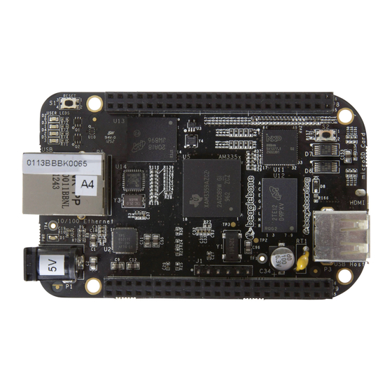
BeagleBone Black System REF: BBONEBLK_SRM Rev A5.2 Reference Manual 10.0 Pictures Figure 67. Top Side Page 105 of 108... -
Page 106: Figure 68. Bottom Side
BeagleBone Black System REF: BBONEBLK_SRM Rev A5.2 Reference Manual Figure 68. Bottom Side Page 106 of 108... -
Page 107: 11.0 Support Information
BeagleBone Black System REF: BBONEBLK_SRM Rev A5.2 Reference Manual 11.0 Support Information All support for this design is through the BeagleBoard.org community at: beagleboard@googlegroups.com http://beagleboard.org/discuss 11.1 Hardware Design Design information can be found on the SD card that ships with board under the documents/hardware directory when connected using the USB cable. -
Page 108: Rma Support
BeagleBone Black System REF: BBONEBLK_SRM Rev A5.2 Reference Manual 11.3 RMA Support If you feel your board is defective or has issues, request an RMA by filling out the form http://beagleboard.org/support/rma . You will need the serial number and revision of the board as shown in the Figure 69 below.
Need help?
Do you have a question about the Black and is the answer not in the manual?
Questions and answers