Mitsubishi Q-Series User Manual
Programmable logic controller
Hide thumbs
Also See for Q-Series:
- User manual (244 pages) ,
- Programming manual (194 pages) ,
- Connectivity manual (5 pages)

Subscribe to Our Youtube Channel
Related Manuals for Mitsubishi Q-Series


Summary of Contents for Mitsubishi Q-Series
- Page 1 Basic Model QCPU(Q Mode) User's Manual (Function Explanation, Program Fundamentals) Mitsubishi Programmable Logic Controller...
- Page 2 1 OVERVIEW MELSEC-Q The following table indicates differences between the Basic model QCPU. Item Q00JCPU Q00CPU Q01CPU CPU module, Power supply CPU module module, Main base unit Stand-alone CPU module (5 slots) Integrated type Main base unit Unnecessary Necessary (Q33B, Q35B, Q38B, Q312B) Extension base unit Connectable (Q52B, Q55B, Q63B, Q65B, Q68B, Q612B) Number of extension stages...
- Page 3 1 OVERVIEW MELSEC-Q 1.1 Features (1) Many controllable input/output points As the number of input/output points accessible to the input/output modules loaded on the base units, 256 points (X/Y0 to FF) are supported by the Q00JCPU and 1024 points (X/Y0 to 3FF) by the Q00CPU/Q01CPU. Up to 2048 points (X/Y0 to 7FF) are supported as the number of input/output device points usable for refreshing the remote input/output of CC-Link and the link inputs and outputs (LX, LY) of MELSECNET/H.
- Page 4 1 OVERVIEW MELSEC-Q (6) Connection of up to four/two extension base units (a) The Q00JCPU can connect up to two extension base units (three base units including the main) and accepts up to 16 modules. (b) The Q00/Q01CPU can connect up to four extension base units (five base units including the main) and accepts up to 24 modules.
-
Page 5: Program Storage
1 OVERVIEW MELSEC-Q 1.2 Program Storage and Calculation (1) Program storage Program created at GX Developer can be stored in Basic model QCPU's program memory or standard ROM. Q00JCPU Q00/Q01CPU Program memory Program memory Parameters Parameters Program Program Comment Comment Standard ROM Standard ROM Parameters... - Page 6 1 OVERVIEW MELSEC-Q (3) Boot operation of program The program stored on the standard ROM is booted (read) to the program memory of the Basic model QCPU and executed. Booting a program from the standard ROM to the program memory requires boot file setting in the PLC parameter.
-
Page 7: Convenient Programming Devices And Instructions
1 OVERVIEW MELSEC-Q 1.3 Convenient Programming Devices and Instructions The Q00J/Q00/A01CPU features devices and instructions which facilitate program creation. A few of these are described below. (1) Flexible device designation (a) Word device bits can be designated to serve as contacts or coils. [For the case of Basic model QCPU] [For the case of AnS] Bit designation of... - Page 8 1 OVERVIEW MELSEC-Q The buffer memory of intelligent function module (e.g. Q64AD, Q62DA) can be used in the same way as devices when programming. [For the case of Basic model QCPU] [For the case of AnS] U4\G12 FROMP Readout of Q64AD buffer memory's address 12 data :U4\G12...
- Page 9 1 OVERVIEW MELSEC-Q (2) Edge relays simplify pulse conversion processing The use of a relay (V) that comes ON at the leading edge of the input condition simplifies pulse processing when a contact index qualification has been made. [Circuit example] M1000 Reset index register (Z1) K1000...
- Page 10 1 OVERVIEW MELSEC-Q Easy shared use of sub-routine programs Subroutine call instructions with arguments will make it easier to create a subroutine programs that makes several calls. Main routine program Argument designation CALLP K4X0 Argument from FD2 Argument to FD1 Argument to FD0 Subroutine program designation...
-
Page 11: System Configuration
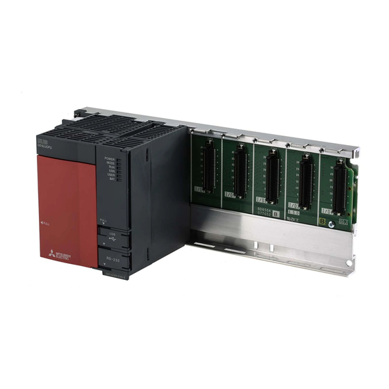
2.1 System Configuration 2.1.1 Q00JCPU This section explains the equipment configuration of a Q00JCPU system and the outline of the system configuration. (1) Equipment configuration MITSUBISHI LITHIUM BATTERY Battery Input/output module/ Basic model QCPU (Q6BAT) - Page 12 2 SYSTEM CONFIGURATION MELSEC-Q (2) Outline of system configuration (b) System including extension base unit and GOT (a) System including extension base units 0 1 2 3 4 Slot number 0 1 2 3 4 Extension Extension cable cable Extension base unit (Q68B) Extension base unit (Q68B) Extension 1 Extension 1...
-
Page 13: Equipment Configuration
2 SYSTEM CONFIGURATION MELSEC-Q 2.1.2 Q00/Q01CPU This section explains the equipment configuration of a Q00/Q01CPU system and the outline of the system configuration. (1) Equipment configuration MITSUBISHI LITHIUM BATTERY Battery Basic model QCPU (Q6BAT) (Q00CPU, Q01CPU) Power supply module/ Main base unit... - Page 14 2 SYSTEM CONFIGURATION MELSEC-Q (2) Outline of system configuration Main base unit (Q312B) Slot No. 0 1 2 3 4 5 6 7 8 9 10 11 Extension cable Extension base unit (Q68B) Extension 1 System configuration Extension base unit (Q65B) Extension 2 Loading will cause error The above system assumes that each slot is loading with...
- Page 15 2 SYSTEM CONFIGURATION MELSEC-Q 2.1.3 Configuration of GX Developer Basic model QCPU Basic model QCPU (Q00JCPU) (Q00CPU, Q01CPU) RS-232 cable (QC30R2) Personal Computer GX Developer (Version 7 or later) 2 - 5 2 - 5...
-
Page 16: Precaution On System Configuration
2 SYSTEM CONFIGURATION MELSEC-Q 2.2 Precaution on System Configuration This section describes hardware and software packages compatible with Basic model QCPU. (1) Hardware (a) The number of modules to be installed and functions are limited depending on the type of the modules. Limit of number of Applicable Module Type... - Page 17 2 SYSTEM CONFIGURATION MELSEC-Q 2.3 Confirming the function version The Basic model QCPU function version can be confirmed on the rating nameplate and GX Developer's system monitor. (1) Confirming the function version on the rating nameplate The function version is indicated on the rating nameplate. MODEL Serial No.
-
Page 18: Performance Specifications
3 PERFORMANCE SPECIFICATION MELSEC-Q 3. PERFORMANCE SPECIFICATION The table below shows the performance specifications of the Basic model QCPU. Performance Specifications Model Item Remark Q00JCPU Q00CPU Q01CPU Control method Repetitive operation of stored program Direct input/output is possible by direct I/O control method Refresh mode input/output... - Page 19 3 HARDWARE SPECIFICATION OF THE CPU MODULE MELSEC-Q Performance Specifications (continued) Model Item Remark Q00JCPU Q00CPU Q01CPU Internal relay [M] Default 8192 points (M0 to 8191) Latch relay [L] Default 2048 points (L0 to 2047) Link relay [B] Default 2048 points (B0 to 7FF) Default 512 points (T0 to 511) (for low / high speed timer) Select between low / high speed timer by instructions.
- Page 20 4 SEQUENCE PROGRAM CONFIGURATION & EXECUTION CONDITIONS MELSEC-Q 4 SEQUENCE PROGRAM CONFIGURATION & EXECUTION CONDITIONS Programs that can be executed by the Basic model QCPU are sequence programs only. This chapter describes the sequence program configuration and execution conditions. 4.1 Sequence Program (1) Definition of sequence program A sequence program is created using sequence instructions, basic instructions, and application instructions, etc.
- Page 21 3 HARDWARE SPECIFICATION OF THE CPU MODULE MELSEC-Q Performance Specifications (continued) Model Item Remark Q00JCPU Q00CPU Q01CPU Special link relay [SB] 1024 points (SB0 to 3FF) Special link register [SW] 1024 points (SW0 to 3FF) Step relay [S] 2048 points (S0 to 2047) Index register [Z] 10 points (Z0 to 9) Pointer [P]...
- Page 22 4 SEQUENCE PROGRAM CONFIGURATION & EXECUTION CONDITIONS MELSEC-Q (2) Sequence program writing format Programming for sequence programs is possible using either ladder mode, or list mode. Ladder mode • The ladder mode is based on the relay control sequence ladder. Programming expressions are similar to the relay control sequence ladder.
-
Page 23: Main Routine Program
4 SEQUENCE PROGRAM CONFIGURATION & EXECUTION CONDITIONS MELSEC-Q 4.1.1 Main routine program (1) Definition of main routine program A main routine program is a program which begins from step 0 and ends at the END/FEND instruction. The main routine program execution begins from step 0 and ends at the END/FEND instruction. -
Page 24: Sub-Routine Programs
4 SEQUENCE PROGRAM CONFIGURATION & EXECUTION CONDITIONS MELSEC-Q 4.1.2 Sub-routine programs (1) Definition of sub-routine program A sub-routine program is a program which begins from a pointer (P ) and ends at a RET instruction. A sub-routine program is executed only when called by a CALL instruction (e.g. -
Page 25: Interrupt Programs
4 SEQUENCE PROGRAM CONFIGURATION & EXECUTION CONDITIONS MELSEC-Q 4.1.3 Interrupt programs (1) Definition of interrupt program An interrupt program is a program which begins at the interrupt pointer ), and ends at the IRET instruction. Interrupt programs are executed only when an interrupt factor occurs. (2) Interrupt program management Interrupt programs are created after the main routine program (after the FEND instruction), and the combination of main and sub-routine programs is managed... - Page 26 4 SEQUENCE PROGRAM CONFIGURATION & EXECUTION CONDITIONS MELSEC-Q (3) Executing interrupt programs To run an interrupt program, interrupts must have been enabled by the EI instruction. If interrupt factors occur before interrupts are enabled, the interrupt factors that occurred are stored, and the interrupt programs corresponding to the stored interrupt factors are executed as soon as interrupts are enabled.
- Page 27 4 SEQUENCE PROGRAM CONFIGURATION & EXECUTION CONDITIONS MELSEC-Q Interruption during a network refresh: If an interrupt factor occurs during a network refresh operation, the network refresh operation is suspended, and the interrupt program is executed. This means that "assurance of blocks in cyclic data at each station" cannot be secured by using a device designated as a destination of link refresh operation on the MESSECNET/H Network System.
- Page 28 4 SEQUENCE PROGRAM CONFIGURATION & EXECUTION CONDITIONS MELSEC-Q (5) Program creation restrictions A device which is switched ON by a PLS instruction in an interrupt program will remain ON until the PLS instruction for the same device is executed again. PLS M0 PLS M0 IO IRET END 0...
- Page 29 4 SEQUENCE PROGRAM CONFIGURATION & EXECUTION CONDITIONS MELSEC-Q 4.2 Concept of Scan Time (1) Scan time The "scan time" is a total of following the execution time of program and END processing. When an interrupt program is executed, the value including the execution time of the interrupt program will be the scan time.
- Page 30 4 SEQUENCE PROGRAM CONFIGURATION & EXECUTION CONDITIONS MELSEC-Q 4.3 Operation Processing 4.3.1 Initial processing This is a preprocessing for sequence operation execution, and is performed only once as shown in the table below. When the initial processing is completed, the Basic model QCPU goes in the RUN/STOP/RESET switch setting status.
-
Page 31: Automatic Refresh Of The Intelligent Function Module
4 SEQUENCE PROGRAM CONFIGURATION & EXECUTION CONDITIONS MELSEC-Q 4.3.2 I/O refresh (I/O module refresh processing) In I/O refresh, an input (X) is received from the input module/intelligent function module, and output (Y) of the Basic model QCPU is produced to the output module/intelligent function module. - Page 32 4 SEQUENCE PROGRAM CONFIGURATION & EXECUTION CONDITIONS MELSEC-Q 4.4 RUN, STOP, PAUSE Operation Processing The Basic model QCPU has three types of operation states; RUN, STOP and PAUSE states. The Basic model QCPU operation processing is explained below: (1) RUN Status Operation Processing RUN status is when the sequence program operation is performed from step 0 to END (FEND) instruction to step 0 repeatedly.
-
Page 33: Operation Processing During Momentary Power Failure
4 SEQUENCE PROGRAM CONFIGURATION & EXECUTION CONDITIONS MELSEC-Q 4.5 Operation Processing during Momentary Power Failure The Basic model QCPU detects a momentary power failure to the power module when the input power voltage is lower than the regulated ranges. When the Basic model QCPU detects a momentary power failure, the following operation processing is performed: (1) When momentary power failure occurs for less than permitted power failure time... -
Page 34: Data Clear Processing
4 SEQUENCE PROGRAM CONFIGURATION & EXECUTION CONDITIONS MELSEC-Q 4.6 Data Clear Processing (1) Data clear The Basic model QCPU clears all data except for the following, when a reset operation is performed with RESET/L.CLR switch, or power ON to OFF to ON. Program memory data Device data with latch specification (latch clear valid) Device data with latch specification (latch clear invalid) -
Page 35: Refresh Mode
4 SEQUENCE PROGRAM CONFIGURATION & EXECUTION CONDITIONS MELSEC-Q 4.7 Input/Output Processing and Response Lag The Basic model QCPU features a refresh type input/output processing format in which a batch communication with the input/output module occurs at END processing. A direct communication format is also possible by using direct access inputs/outputs at the sequence program to enable direct communication with the input/output module when the sequence program instructions are executed. - Page 36 4 SEQUENCE PROGRAM CONFIGURATION & EXECUTION CONDITIONS MELSEC-Q REMARK 1: The GX Developer input area can be switched ON and OFF by the following: • Test operation by the GX Developer • A network refresh by the MELSECNET/H network system •...
- Page 37 4 SEQUENCE PROGRAM CONFIGURATION & EXECUTION CONDITIONS MELSEC-Q (2) Response lag Output response lags of up to 2 scans can result from input module changes. (See Fig.4.7) Ladder examples Ladder for switching the Y5E output ON in response to an X5 input ON. Fastest possible Y5E ON Input refresh Input refresh...
-
Page 38: Direct Mode
4 SEQUENCE PROGRAM CONFIGURATION & EXECUTION CONDITIONS MELSEC-Q 4.7.2 Direct mode (1) Definition of direct mode In the direct mode the communication with the input/output modules is performed when executing sequence program instructions. With Basic model QCPU, direct mode I/O processing can be executed by using direct access inputs (DX) and direct access outputs (DY). - Page 39 4 SEQUENCE PROGRAM CONFIGURATION & EXECUTION CONDITIONS MELSEC-Q (2) Response lag Output response lags of up to 1 scans can result from input module changes. (See Fig.4.10) Ladder examples Ladder for switching the DY5E output DY5E ON in response to an DX5 input ON. Fastest possible DY5E ON LD DX5 OUT DY5E...
-
Page 40: Numeric Values Which Can Be Used In Sequence Programs
4 SEQUENCE PROGRAM CONFIGURATION & EXECUTION CONDITIONS MELSEC-Q 4.8 Numeric Values which Can Be Used in Sequence Programs Numeric and alphabetic data are expressed by "0" (OFF) and "1" (ON) numerals in the Basic model QCPU. This method of expression is called "binary code" (BIN). The hexadecimal (HEX) expression method in which BIN data are expressed in 4-bit units, and the BCD (binary coded decimal) expression method are also possible for the Basic model QCPU. - Page 41 4 SEQUENCE PROGRAM CONFIGURATION & EXECUTION CONDITIONS MELSEC-Q (1) External numeric inputs to Basic model QCPU When designating numeric settings for the Basic model QCPU from an external source (digital switch, etc.), a BCD (binary coded decimal) setting can be designated which is the same as a decimal setting.
-
Page 42: Binary Code
4 SEQUENCE PROGRAM CONFIGURATION & EXECUTION CONDITIONS MELSEC-Q 4.8.1 BIN (Binary Code) (1) Binary code In binary code, numeric values are expressed by numerals "0" (OFF) and "1" (ON) numerals. When counting in the decimal system, a carry to the "tens" column occurs following 9 (8 to 9 to 10). -
Page 43: Hexadecimal Notation
4 SEQUENCE PROGRAM CONFIGURATION & EXECUTION CONDITIONS MELSEC-Q 4.8.2 HEX (Hexadecimal) (1) Hexadecimal notation In the hexadecimal system, 4 bits of binary data are expressed by 1 digit. 4 bits of binary data can express 16 values (0 to 15). In the hexadecimal system, values from 0 to 15 are expressed by 1 digit. - Page 44 4 SEQUENCE PROGRAM CONFIGURATION & EXECUTION CONDITIONS MELSEC-Q 4.8.3 BCD (Binary Coded Decimal) (1) BCD notation BCD numeric expressions are binary expressions with a carry format identical to that of the decimal system. As with the hexadecimal system, BCD expressions are the equivalent of 4 binary bits, although the BCD system does not use the A to F alphabetic characters.
-
Page 45: Character String Data
4 SEQUENCE PROGRAM CONFIGURATION & EXECUTION CONDITIONS MELSEC-Q 4.9 Character String Data (1) Character String Data The Basic model QCPU uses ASCII code data. (2) ASCII code character strings ASCII code character strings are shown in the Table below. "00 "... -
Page 46: Assignment Of I/O Numbers
5 ASSIGNMENT OF I/O NUMBERS MELSEC-Q 5 ASSIGNMENT OF I/O NUMBERS This section describes the necessary information on the I/O number assignment for the data exchange between Basic model QCPU and input/output modules or intelligent function modules. 5.1 Relationship Between the Number of Stages and Slots of the Extension Base Unit 5.1.1 Q00JCPU The Q00JCPU can configure a system with a total of three base units: one main base unit and two extension base units. -
Page 47: Self-Diagnosis Function
7 FUNCTION MELSEC-Q 7.12 Self-Diagnosis Function (1) What is Self-Diagnosis Function? The self-diagnosis is a function performed by Basic model QCPU itself to diagnose whether there is an error in the Basic model QCPU. The self-diagnosis function's objective is to prevent Basic model QCPU erroneous operation and as preventive maintenance. - Page 48 7 FUNCTION MELSEC-Q (4) Error check selection The error checking can be set to "yes/no" in the following error checking in the parameter mode PLC RAS setting. (All parameter defaults are set at "Yes".) Battery check Fuse blown check I/O unit comparison Self-Diagnosis List Diagnosis description Error message...
- Page 49 7 FUNCTION MELSEC-Q Self-Diagnosis List (Continued from the preceding page) Diagnosis description Error message Diagnostic timing • When the power is turned on/when reset Instruction code check INSTRUCT CODE.ERR. • When switched from STOP to RUN • When the power is turned on/when reset No END instruction MISSING END INS.
-
Page 50: Led Display When Error Occurs
7 FUNCTION MELSEC-Q 7.12.1 LED display when error occurs When an error occurs, the ERR. LED located on the front of Basic model QCPU turns Refer to Section 7.19 for the details of the ERR. LED operation. 7.12.2 Cancel error Basic model QCPU error cancel operation can be performed only for error that can continue the Basic model QCPU operation. - Page 51 7 FUNCTION MELSEC-Q 7.13 Failure History The Basic model QCPU can store the failure history (results detected from the self- diagnosis function and the time) in the memory. POINT The detection time uses the Basic model QCPU internal clock, so make sure to set the correct time when first using Basic model QCPU.
-
Page 52: System Protect
7 FUNCTION MELSEC-Q 7.14 System Protect Basic model QCPU has a few protection functions (system protect) for the program changes to processing of general data obtained from a third party other than the designer (access processing from GX Developer function or serial communication module). - Page 53 7 FUNCTION MELSEC-Q (1) Password Registration To perform the password registration, select GX Developer Online Password setup/keyword set up for writing to PLC Register password. Each item is described below: Target memory ....Set the memory storing the file whose password is to be registered or changed. Data type......Specifies the type of a file stored in the target memory.
- Page 54 7 FUNCTION MELSEC-Q 7.15 GX Developer system monitor It is possible to confirm the following information for Basic model QCPUs connected to personal computers with the GX Developer system monitor (see illustration below.) • Installed status • Operation status • Module’s detailed information •...
- Page 55 7 FUNCTION MELSEC-Q Module’s detailed information This function is used to confirm the detailed information for selected modules. Refer to the instruction manual for the relevant intelligent function module for details on the detailed information for intelligent function modules. Base information Enables the "Overall Information"...
-
Page 56: Led Display
7 FUNCTION MELSEC-Q 7.16 LED Display The LEDs that indicate the operation statuses of the Basic model QCPU are provided on the front panel of the Basic model QCPU. The indications of the LEDs are described below. (1) The details of the LED display are shown below: LED name Display Description Indicates Basic model QCPU operation status. - Page 57 7 FUNCTION MELSEC-Q (2) How to turn off the ERR. LED To turn off the ERR. LED that is on, remove the cause of the error and then operate the special relay SM50 and special register SD50 to cancel the error. (This does not apply to reset operation.) REMARK Refer to Section 7.12.2 for canceling the error.
- Page 58 7 FUNCTION MELSEC-Q 7.17 Serial Communication Function (Usable with the Q00CPU or Q01CPU) The serial communication function is designed to make communication in the MC protocol (*1) by connecting the RS-232 interface of the CPU module and personal computer, display device or the like by an RS-232 cable. The serial communication function is not used for connection of GX Developer or GX Configurator and the CPU module.
- Page 59 7 FUNCTION MELSEC-Q (1) Specifications Transmission specifications The following table indicates the transmission specifications of RS-232 used for the serial communication function of the CPU module. Use the serial communication function after making sure that the specifications of the personal computer, Display device or the like match those of the following table.
- Page 60 7 FUNCTION MELSEC-Q RS-232 connector specifications The following table indicates the applications of the RS-232 connector of the Q00CPU/Q01CPU. Appearance Pin No. Signal Symbol Signal Name RD (RXD) Receive data SD (TXD) Send data Signal ground Mini-Din 6 pins DSR (DR) Data set ready (female)
- Page 61 7 FUNCTION MELSEC-Q (2) Functions The serial communication function allows the MC protocol commands in the following table to be executed. Refer to the following manual for details of the MC protocol. • Q-Compatible MELSEC Communication Protocol Reference Manual Function Command Processing Processing Points...
-
Page 62: Accessible Devices
7 FUNCTION MELSEC-Q (3) Accessible devices Device Number Class Device Device Code Range Write Read (Default Value) Internal system Function input 000000 to 00000F device Function output 000000 to 00000F Function register 000000 to 000004 Special relay 000000 to 001023 Special register 000000 to 001023 Internal user... - Page 63 7 FUNCTION MELSEC-Q (4) Setting of transmission specifications Use the serial communication setting PLC parameters to set the transmission speed, sum check, transmission wait time and write during RUN setting of the serial communication function. (a) When using the serial communication function to make communication with the personal computer, Display device or the like, specify "Use serial communication".
- Page 64 7 FUNCTION MELSEC-Q (6) Error codes for communication made using serial communication function The following table indicates the error codes, error definitions and corrective actions that are sent from the Q00CPU or Q01CPU to the external device when errors occur during communication made using the serial communication function.
- Page 65 7 FUNCTION MELSEC-Q Error Code Error Item Error Definition Corrective Action (Hexadecimal) • The command or device specified does • Check and correct the sent message of the 7F22H Command error not exist. device on the other end and restart •...
-
Page 66: Communication With Intelligent Function Module
Basic model QCPU reads/writes the data from/to the buffer memory. 8.1 Communication Between Basic model QCPU and Q-series Intelligent Function Modules The following methods enable the communication between Basic model QCPU and intelligent function modules: •... - Page 67 11 PROCESSING TIMES OF THE BASIC MODEL QCPU MELSEC-Q (6) Service processing time (a) Monitoring using GX Developer Processing time (unit: ms) for monitoring using GX Developer. Added when monitoring is performed on GX Developer. When Connected to RS-232 of Host CPU When Connected to Other Station Module Function...
- Page 68 12 PROCEDURE FOR WRITING PROGRAMS TO BASIC MODEL QCPU MELSEC-Q 12 PROCEDURE FOR WRITING PROGRAM TO BASIC MODEL QCPU This chapter describes the procedure for writing program created at the GX Developer to the Basic model QCPU. 12.1 Items to Consider when Creating Program In order to create a program, the program size, number of device points used, and the program file name, etc., must be set in advance.
- Page 69 12 PROCEDURE FOR WRITING PROGRAMS TO BASIC MODEL QCPU MELSEC-Q 12.2 Procedure for writing program to the Basic model QCPU The procedure for writing program and parameter created at the GX Developer to the Basic model QCPU standard ROM is shown below. When writing program and parameter to the Basic model QCPU program memory, the steps indicated by asterisks ( ) below are not required.
- Page 70 12 PROCEDURE FOR WRITING PROGRAMS TO BASIC MODEL QCPU MELSEC-Q Refer to the GX Developer manual. Connect GX Developer and CPU module. ERR. LED is lit. Move the RUN/STOP/RESET switch of the CPU module to the STOP position and switch power on.
-
Page 71: Appendix 1 Special Relay List
APPENDICES MELSEC-Q APPENDICES APPENDIX 1 Special Relay List Special relays, SM, are internal relays whose applications are fixed in the programmable controller. For this reason, they cannot be used by sequence programs in the same way as the normal internal relays. However, they can be turned ON or OFF as needed in order to control the CPU and remote I/O modules. - Page 72 11 PROCESSING TIMES OF THE BASIC MODEL QCPU MELSEC-Q 3) As KN1 and KN2, use the values in the following table. When the intelligent module is installed on the main base unit KN1 ( 10 KN2 ( 10 CPU Type Q00JCPU Q00CPU Q01CPU...
- Page 73 APPENDICES MELSEC-Q Special Relay List (1) Diagnostic Information Number Name Meaning Explanation Set by (When Set) • ON if diagnosis results show error occurrence OFF: No error Diagnostic errors (Includes external diagnosis) S (Error) ON : Error • Stays ON subsequently even if normal operations restored OFF: No self-diagnosis Self-diagnostic •...
Need help?
Do you have a question about the Q-Series and is the answer not in the manual?
Questions and answers