Advertisement
Quick Links
Electric Heater
Packages
NOTE: Read the entire instruction manual before starting the installation.
This symbol → indicates a change since the last issue.
Installing and servicing heating and air conditioning equipment can be hazardous due to system pressures and electrical components. Only trained
personnel should install or service heating and air conditioning equipment.
Untrained personnel can perform basic maintenance functions such as cleaning coils, or cleaning and replacing filters. All other operations should
be performed by trained service personnel. When working on heating and air conditioning equipment, observe precautions in the literature, on tags,
and on labels attached to the unit.
Follow all safety codes. Wear safety glasses and work gloves. Have a fire extinguisher available.
Recognize safety information. This is the safety-alert symbol
When you see this symbol on the unit and in instructions or manuals, be alert to the potential for personal injury.
Understand the signal words DANGER, WARNING, CAUTION, and NOTE. These words are used with the safety-alert symbol. DANGER
identifies the most serious hazards which will result in severe personal injury or death. WARNING signifies hazards which could result in personal
injury or death. CAUTION is used to identify unsafe practices which would result in minor personal injury or product and property damage. NOTE
is used to highlight suggestions which will result in enhanced installation, reliability, or operation.
WARNING: Before beginning any installation or modification, be sure the main electrical disconnect switch is in the
OFF position. Tag the disconnect switch with a suitable warning label. Electrical shock can cause personal injury or death.
Form: AG-FCEH-09
Installation Instructions
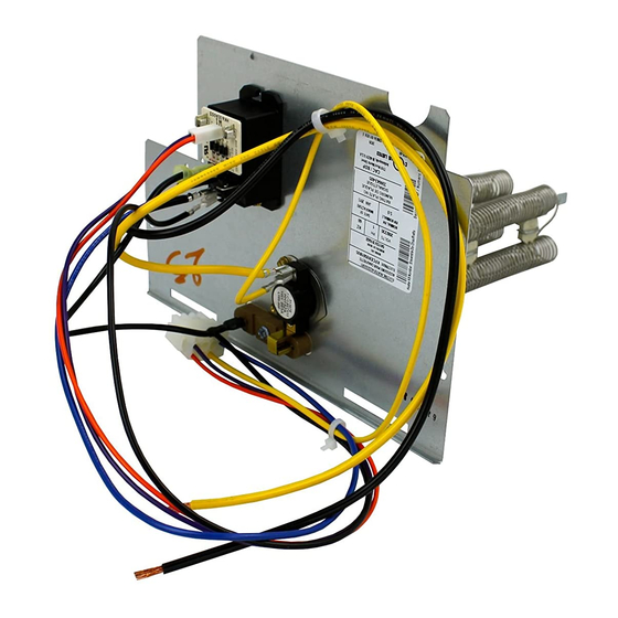
SINGLE-CIRCUIT
GROUND LUG
TERMINAL
BLOCK
MULTI-CIRCUIT
GROUND LUG
CLIP LATCH
Fig. 1—Installation of 18-, 24-, and 30-kw Model Heaters
SAFETY CONSIDERATIONS
Cancels: AG-FCEH-08
ADAPTER PLATE
(MUST BE REMOVED WHEN
INSTALLING LARGE HEATER)
FUSE BLOCK
(24- AND 30-KW)
FUSE COVER
(OMITTED ON 18-KW)
.
Printed in U.S.A.
4-03
KFCEH
A90154
Catalog No. 63FC-EH7
Advertisement

Related Manuals for Carrier KFCEH0401N03


Summary of Contents for Carrier KFCEH0401N03
- Page 1 Installation Instructions Electric Heater KFCEH Packages NOTE: Read the entire instruction manual before starting the installation. This symbol → indicates a change since the last issue. SINGLE-CIRCUIT GROUND LUG TERMINAL BLOCK MULTI-CIRCUIT GROUND LUG ADAPTER PLATE (MUST BE REMOVED WHEN INSTALLING LARGE HEATER) FUSE BLOCK (24- AND 30-KW)
-
Page 2: Installation
MODEL FC MODEL FH MODEL FX FE4, FK4, FV4, 40FK INTELLIGENT PART NO. PROTECTION SIZE SIZE SIZE SIZE SIZE HEAT CAPABLE 1 Phase KFCEH0401N03 Non-fused 018, 024 — — KFCEH0501N05 Non-fused 018-071 024-070 001-004 030-060 001-006 KFCEH2401C05 Circuit Breaker KFCEH0801N08... - Page 3 PROCEDURE 2—ATTACH FUSE BOX OR CIRCUIT BREAKER BOX 1. For 15- and 20-kw fused models: After installing heater assembly, attach fuse assembly to side of fan coil unit by inserting fuse box tab between insulation and to left side of unit and fan deck. Mount front of assembly to side flange with 2 screws provided. On fan coil units size 042 and larger, remove wire tie that shortens wire length between heater and fuses.
- Page 4 —4—...
- Page 5 SINGLE DUAL CIRCUIT CIRCUIT GROUND LUG GROUND LINE SIDE CONNECTION BLOWER SHELF COIL WIRES TO HEATER WIRE TIE COVER WIRE ROUTING MOUNTING (REMOVE ON LOAD SIDE BRACKET PLATE LARGER UNITS) A90153 Fig. 3—Installation of Circuit Breaker Model Heater A03069 → Fig. 4—Installation of Window Bezel for Circuit Breaker Model Heater A.
- Page 6 SECONDARY PRIMARY A94067 Fig. 5—Connection of Transformer 3. Heater staging The units are shipped circuited for single-stage operation. Use outdoor thermostat kit Part No. KHAOT0301FST for 2-stage operation. Use both kit Part No. KHAOT0201SEC and KHAOT0301FST for 3-stage operation. When 2-stages are desired, cut W3 at the W2 wire nut, strip and reconnect per wiring staging layout in Installation Instructions for fan coils.
- Page 7 3. Fused heaters: (See Fig. 8, 12, 13, and 14.) a. The 15- and 20-kw heaters can be wired for single- or dual-supply circuits. Single-supply circuit wiring requires a factory-authorized, single-point adapter kit. b. The 24- and 30-kw heaters can be wired for single- or multiple-supply circuits. Heaters are factory wired for single circuit 3 phase. To convert heaters to single circuit single phase, disconnect yellow lead from L3 and connect to L1.
- Page 8 Yellow Field Field Power Power Black Wiring Wiring Blue Ground lug Ground lug Field Field Ground Ground Wiring Wiring A00080 A00081 Fig. 10—15kw 3-Phase Heater Fig. 11—18kw 3-Phase Heater Field Field Power Power Wiring Wiring Field Ground Field Ground Ground lug Ground lug Wiring Wiring...
-
Page 9: Wire Color
FAN RELAY SINGLE SPADE INSULATING CAP (2) MOTOR SPEED TAP LEADS SPEED TAP 2 OR 3 TERMINAL WRAPPER COMMON YELLOW FAN DECK A94068 Fig. 15—Motor Speed Tap and Fan Relay C. Ground Connections WARNING: According to NEC, ANSI/NFPA 70, and local codes, cabinet must have an uninterrupted or unbroken ground to minimize personal injury if an electrical fault should occur. - Page 10 RELEASE TAB A99094 Fig. 16—Conversion of Circuit Breaker PROCEDURE 4—CONVERSION OF CIRCUIT BREAKER FOR DOWNFLOW APPLICATIONS 1. Tag and disconnect factory wiring from terminals on circuit breaker(s). 2. Pull white plastic release tab on the bottom of circuit breaker straight out to release circuit breaker from bracket. (See Fig. 16.) 3.
- Page 11 UNIT RATING LABEL ON DOOR HEATER LABEL FROM KIT A96251 Fig. 17—Heater Rating Label Location Table 7—FK4C, FV4A, 40FK, PF1MNB071 Airflow Delivery (CFM) - Electric Heating Modes OUTDOOR ELECTRIC HEATER KW RANGE UNIT UNIT 0—5 0—10 0—15 0—20 CAPACITY SIZE BTUH 18,000 24,000...
- Page 12 Table 8—FE4A Fan Coil Airflow Delivery (cfm) -- Electric Heating Modes OUTDOOR ELECTRIC HEATER KW RANGE MODEL UNIT FE4A CAPACITY 8,9,10 18,20 BTUH EMERGENCY 1025 18,000 24,000 30,000 1050 1125 36,000 1000 1050 1125 1225 EMERGENCY 1100 24,000 30,000 1100 1150 36,000 1025...
Need help?
Do you have a question about the KFCEH0401N03 and is the answer not in the manual?
Questions and answers