Table of Contents
Advertisement
Quick Links
Advertisement
Table of Contents

Related Manuals for ABB IRB 6660 - 130/3.1


Summary of Contents for ABB IRB 6660 - 130/3.1
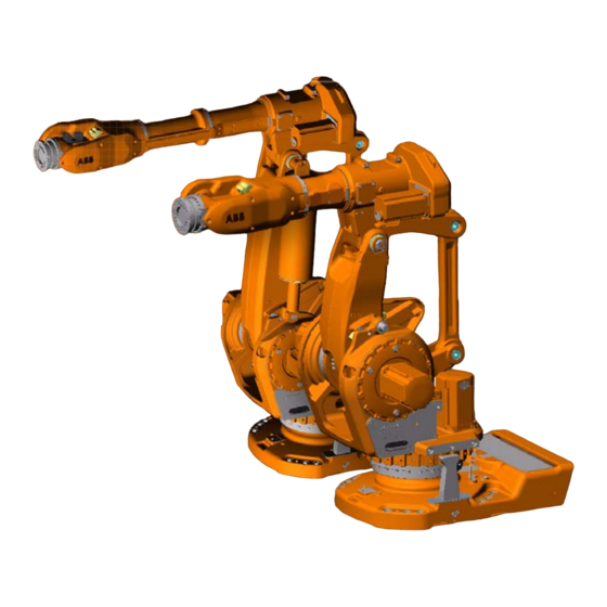
- Page 1 Product manual Articulated robot IRB 6660 - 130/3.1 IRB 6660 - 205/1.9 M2004...
- Page 3 Product manual IRB 6660 - 130/3.1 IRB 6660 - 205/1.9 M 2004 Document ID: 3HAC028197-001 Revision: A...
- Page 4 Except as may be expressly stated anywhere in this manual, nothing herein shall be construed as any kind of guarantee or warranty by ABB for losses, damages to persons or property, fitness for a specific purpose or the like.
-
Page 5: Table Of Contents
Table of Contents Overview ................7 Product documentation, M2004 . - Page 6 Table of Contents 2.5 Electrical connections ............. . 81 2.5.1 Robot cabling and connection points .
- Page 7 Table of Contents 4.4.6 Replacement of parallel arm........... . . 208 4.5 Frame and base.
- Page 8 Table of Contents 9 Circuit diagram 9.1 Introduction ..............307 Index 3HAC028197-001 Revision: A...
-
Page 9: Overview
Prerequisites A maintenance/repair/ installation craftsman working with an ABB Robot must: • be trained by ABB and have the required knowledge of mechanical and electrical installation/repair/maintenance work. Organization of chapters The manual is organized in the following chapters:... - Page 10 Overview Continued Chapter Contents Reference information Useful information when performing installation, maintenance or repair work. Includes lists of necessary tools, additional documents, safety standards etc. Spare part / part list Complete spare part list and complete list of robot components, shown in exploded views.
-
Page 11: Product Documentation, M2004
This means that any given delivery of robot products will not contain all documents listed, only the ones pertaining to the equipment delivered. However, all documents listed may be ordered from ABB. The documents listed are valid for M2004 robot systems. - Page 12 Product documentation, M2004 Continued Operating manuals This group of manuals is aimed at those having first hand operational contact with the robot, that is production cell operators, programmers and trouble shooters. The group of manuals includes: • Emergency safety information •...
-
Page 13: How To Read The Product Manual
How to read the product manual How to read the product manual Reading the procedures The procedures contain references to figures, tools, material etc. The references are read as described below. References to figures The procedures often include references to components or attachment points located on the robot/controller. - Page 14 How to read the product manual 3HAC028197-001 Revision: A...
-
Page 15: Safety
1 Safety 1.1. Introduction 1 Safety 1.1. Introduction Overview The safety information in this manual is divided in two categories: • general safety aspects, important to attend to before performing any service work on the robot. These are applicable for all service work and are found in section General safety information. -
Page 16: General Safety Information
Limitation of liability Any information given in this manual regarding safety, must not be construed as a warranty by ABB that the industrial robot will not cause injury or damage even if all safety instructions are complied with. Related information... -
Page 17: Safety Risks
Nation/region specific regulations To prevent injuries and damage during the installation of the robot system, the regulations applicable in the country concerned and the instructions of ABB Robotics must be complied with. Non-voltage related risks •... - Page 18 1 Safety 1.2.2.1. Safety risks during installation and service work on robot Continued Complete robot Safety risk Description Hot components! CAUTION! Motors and gears are HOT after running the robot! Touching motors and gears may result in burns! With higher environment temperature more surfaces on the robot are getting HOT and may result in burns too! Removed parts may result in collapse of robot!
-
Page 19: Safety Risks Related To Tools/Workpieces
1 Safety 1.2.2.2. Safety risks related to tools/workpieces 1.2.2.2. Safety risks related to tools/workpieces Safe handling It must be possible to safely turn off tools, such as milling cutters, etc. Make sure that guards remain closed until the cutters stop rotating. It should be possible to release parts by manual operation (valves). -
Page 20: Safety Risks Related To Pneumatic/Hydraulic Systems
1 Safety 1.2.2.3. Safety risks related to pneumatic/hydraulic systems 1.2.2.3. Safety risks related to pneumatic/hydraulic systems General Special safety regulations apply to pneumatic and hydraulic systems. Residual energy • Residual energy may be present in these systems. After shutdown, particular care must be taken. -
Page 21: Safety Risks During Operational Disturbances
1 Safety 1.2.2.4. Safety risks during operational disturbances 1.2.2.4. Safety risks during operational disturbances General • The industrial robot is a flexible tool which can be used in many different industrial applications. • All work must be carried out professionally and in accordance with the applicable safety regulations. -
Page 22: Risks Associated With Live Electric Parts
1 Safety 1.2.2.5. Risks associated with live electric parts 1.2.2.5. Risks associated with live electric parts Voltage related risks, general • Although troubleshooting may, on occasion, need to be carried out while the power supply is turned on, the robot must be turned off (by setting the mains switch to OFF) when repairing faults, disconnecting electric leads and disconnecting or connecting units. -
Page 23: Safety Actions
1 Safety 1.2.3.1. Safety fence dimensions 1.2.3. Safety actions 1.2.3.1. Safety fence dimensions General Install a safety cell around the robot to ensure safe robot installation and operation. Dimensioning Dimension the fence or enclosure to enable it to withstand the force created if the load being handled by the robot is dropped or released at maximum speed. -
Page 24: Fire Extinguishing
1 Safety 1.2.3.2. Fire extinguishing 1.2.3.2. Fire extinguishing NOTE! Use a CARBON DIOXIDE (CO ) extinguisher in the event of a fire in the robot system (robot or controller)! 3HAC028197-001 Revision: A... -
Page 25: Emergency Release Of The Robot's Arm
1 Safety 1.2.3.3. Emergency release of the robot’s arm 1.2.3.3. Emergency release of the robot’s arm Description In an emergency situation, any of the robot's axes may be released manually by pushing the brake release buttons on the robot. How to release the brakes is detailed in section: •... -
Page 26: Brake Testing
1 Safety 1.2.3.4. Brake testing 1.2.3.4. Brake testing When to test During operation the holding brake of each axis motor wear normally. A test may be performed to determine whether the brake can still perform its function. How to test The function of the holding brake of each axis motor may be checked as detailed below: 1. -
Page 27: Risk Of Disabling Function "Reduced Speed 250 Mm/S
1 Safety 1.2.3.5. Risk of disabling function "Reduced speed 250 mm/s" 1.2.3.5. Risk of disabling function "Reduced speed 250 mm/s" NOTE! Do not change "Transm gear ratio" or other kinematic system parameters from the FlexPendant or a PC. This will affect the safety function "Reduced speed 250 mm/s". 3HAC028197-001 Revision: A... -
Page 28: Safe Use Of The Flexpendant
1 Safety 1.2.3.6. Safe use of the FlexPendant 1.2.3.6. Safe use of the FlexPendant NOTE! The enabling device is a push button located on the side of the FlexPendant which, when pressed halfway in, takes the system to MOTORS ON. When the enabling device is released or pushed all the way in, the robot is taken to the MOTORS OFF state. -
Page 29: Work Inside The Robot's Working Range
1 Safety 1.2.3.7. Work inside the robot's working range 1.2.3.7. Work inside the robot's working range WARNING! If work must be carried out within the robot’s work envelope, the following points must be observed: • The operating mode selector on the controller must be in the manual mode position to render the enabling device operative and to block operation from a computer link or remote control panel. -
Page 30: Signal Lamp (Optional)
1 Safety 1.2.3.8. Signal lamp (optional) 1.2.3.8. Signal lamp (optional) Description A signal lamp with an yellow fixed light can be mounted on the robot, as a safety device. Function The lamp is active in MOTORS ON mode. Further information Further information about the MOTORS ON/MOTORS OFF mode may be found in the controller documentation. -
Page 31: Translate The Information On Safety And Information Labels
Using a transparent sticker over the standard label with text added in a fourth language. Drawings detailing the design (text, figure, dimensions) of the standard labels can be ordered from ABB. Notice that each label is identified according to the article number located in the lower corner of the label. -
Page 32: Safety Related Instructions
1 Safety 1.3.1. Safety signals, general 1.3 Safety related instructions 1.3.1. Safety signals, general General This section specifies all dangers that may arise from performing the work detailed in the manual. Each danger is detailed in its own section consisting of: •... - Page 33 1 Safety 1.3.1. Safety signals, general Continued Symbol Designation Signification ELECTROSTATIC The electrostatic discharge (ESD) symbol indicates DISCHARGE (ESD) electrostatic hazards which could result in severe damage to the product. Electrostatic discharge (ESD) NOTE Note symbols alert you to important facts and conditions.
-
Page 34: Danger - Moving Robots Are Potentially Lethal
1 Safety 1.3.2. DANGER - Moving robots are potentially lethal! 1.3.2. DANGER - Moving robots are potentially lethal! Description Any moving robot is a potentially lethal machine. When running the robot, it may perform unexpected and sometimes irrational movements. However, all movements are performed with great force and may seriously injure any personnel and/or damage any piece of equipment located within the working range of the robot. -
Page 35: Danger - First Test Run May Cause Injury Or Damage
1 Safety 1.3.3. DANGER - First test run may cause injury or damage! 1.3.3. DANGER - First test run may cause injury or damage! Description Since performing a service activity often requires disassembly of the robot there are several safety risks to take into consideration before the first test run. Elimination Follow the procedure below when performing the first test run after a service activity (repair, installation or maintenance):... -
Page 36: Warning - The Brake Release Buttons May Be Jammed After Service Work
1 Safety 1.3.4. WARNING - The brake release buttons may be jammed after service work 1.3.4. WARNING - The brake release buttons may be jammed after service work Description The brake release unit has push buttons for brake release of each axis motor. When service work is performed inside the SMB recess that includes removal and refitting of the brake release unit, the brake release buttons may be jammed after refitting. -
Page 37: Warning - The Unit Is Sensitive To Esd
1 Safety 1.3.5. WARNING - The unit is sensitive to ESD! 1.3.5. WARNING - The unit is sensitive to ESD! Description ESD (electrostatic discharge) is the transfer of electrical static charge between two bodies at different potentials, either through direct contact or through an induced electrical field. When handling parts or their containers, personnel not grounded may potentially transfer high static charges. -
Page 38: Warning - Safety Risks During Work With Gearbox Oil
1 Safety 1.3.6. WARNING - Safety risks during work with gearbox oil 1.3.6. WARNING - Safety risks during work with gearbox oil Description When handling the gearbox oil, there are several dangers to both personal injuries and product damages! Following safety information must be regarded before performing any work with the oil in the gearboxes! Warnings and elimination Warning... -
Page 39: Installation And Commissioning
2 Installation and commissioning 2.1. Introduction 2 Installation and commissioning 2.1. Introduction General This chapter contains information for installing the robot to the working site. More detailed technical data, such as load diagram, permitted extra loads (equipment) and location of extra loads (equipment), may be found in the Product Specification for the robot. 3HAC028197-001 Revision: A... -
Page 40: Unpacking
Weight, robot The table below shows the weights of the different models: Robot model Weight IRB 6660 - 130/3.1 1910 kg IRB 6660 - 205/1.9 1730 kg Loads on foundation, robot The table below shows the various forces and torques working on the foundation during different kinds of operation, in relation to the base coordinate system. - Page 41 0.5 mm Max. tilt 5° The limit for the maximum load on the robot is reduced if the robot is tilted. Contact ABB for further information about acceptable loads. Min. resonance frequency 22 Hz Storage conditions, robot The table below shows the allowed storage conditions for the robot:...
-
Page 42: Working Range And Type Of Motion
Working range The following figures show the working ranges of the robot models. The extreme positions of the robot arm are specified at the wrist center (dimensions in mm). IRB 6660 - 130/3.1 xx0700000011 Continues on next page 3HAC028197-001 Revision: A... - Page 43 2 Installation and commissioning 2.2.2. Working range and type of motion Continued IRB 6660 - 205/1.9 xx0700000563 Type of motion Axis Type of motion Range of movement Note Rotation motion +180º to -180º Arm motion +85° to -42° Arm motion +120°...
-
Page 44: Risk Of Tipping / Stability
The figure below shows the robot in its shipping position, which also is its most stable position. xx0700000001 IRB 6660 - 130/3.1 IRB 6660 - 205/1.9 WARNING! The robot is likely to be mechanically unstable while not secured to the foundation! -
Page 45: On-Site Installation
2 Installation and commissioning 2.3.1. Lifting robot with fork lift 2.3 On-site installation 2.3.1. Lifting robot with fork lift General The robot may be moved using a fork lift, provided that available special aids are used. This section describes how to attach the fork lift equipment to the robot. Attachment points The attachment points for the fork lift equipment are shown in the figure below. - Page 46 2 Installation and commissioning 2.3.1. Lifting robot with fork lift Continued Fork lift set, 3HAC023044-001 The fork lift set 3HAC023044-001, is fitted to the robot as shown in the figure below. xx0500002277 Fork lift pocket (2 pcs, one long & one short) Adapter (1 + 1 pcs) Horizontal attachment screws (4 pcs/fork lift pocket) Attachment screws for adapter (1 pc/adapter)
- Page 47 Manually releasing the brakes on page xx0700000517 • A: IRB 6660 - 130/3.1 • B: IRB 6660 - 205/1.9 3. Fit the two adapters to the robot and secure. Attachment points on the robot are shown in the figure...
- Page 48 2 Installation and commissioning 2.3.1. Lifting robot with fork lift Continued Action Note 4. Strap up the axis 2 motor cable on the adapter. xx0500002278 • A: Strap, velcro CAUTION! The fork lift pocket weighs 60 kg! 6. Secure the longer fork lift pocket to the adapter Make sure the original screws are and frame with four of the horizontal always used (or replacements of...
- Page 49 2 Installation and commissioning 2.3.1. Lifting robot with fork lift Continued Action Note 7. Make sure the securing screw is removed from the fork lift pocket! It is only used for robot model IRB 6650S. xx0700000655 • A: Securing screw must be removed! 8.
- Page 50 2 Installation and commissioning 2.3.1. Lifting robot with fork lift Continued Action Note 11. Double-check that the pockets are properly secured to the robot! Insert the fork lift forks into the pockets. CAUTION! NOTE! The robot models weigh: • IRB6660-130/3.1: 1910 kg The weight (90 kg) of the fork lift pockets must be added to the robot •...
-
Page 51: Lifting Robot With Roundslings
Attachment points The figure below shows how to attach the roundslings to the robot. xx0700000002 IRB 6660 - 130/3.1 Roundsling 2 m Roundsling 2 m Roundsling 2 m Continues on next page... - Page 52 2 Installation and commissioning 2.3.2. Lifting robot with roundslings Continued xx0700000426 IRB 6660 - 205/1.9 Roundsling 2 m Roundsling 2 m Roundsling 2 m Sling specification Sling type Lifting capacity Length / Note Roundsling, robot 3 pcs 3 000 kg Continues on next page 3HAC028197-001 Revision: A...
- Page 53 2 Installation and commissioning 2.3.2. Lifting robot with roundslings Continued Lifting with roundslings Action Note 1. Attach the roundslings to the robot according to the figure Attachment points on page NOTE! For Cleanroom robots it is important to apply the roundslings: •...
-
Page 54: Lifting Robot With Lifting Slings
Attempting to lift a robot in any other position may result in the robot tipping over, causing severe damage or injury! Illustration, lifting slings The figure below shows how to lift the complete robot with lifting slings. xx0700000004 IRB 6660 - 130/3.1 Load hook Swivelling lifting eyes, 4 pcs Shortening hook Chain Lifting eye, M12 Lifting device´s eye... - Page 55 2 Installation and commissioning 2.3.3. Lifting robot with lifting slings Continued xx0700000427 IRB 6660 - 205/1.9 Load hook Swivelling lifting eyes, 4 pcs Shortening hook Chain Lifting eye, M12 Lifting device´s eye Lifting slings, 4 pcs Hook Required equipment Equipment Art.
- Page 56 If it is not, position it that detailed in section Manually releasing the brakes on page xx0700000137 • IRB 6660 - 130/3.1 xx0700000518 • IRB 6660 - 205/1.9 Continues on next page 3HAC028197-001 Revision: A...
- Page 57 2 Installation and commissioning 2.3.3. Lifting robot with lifting slings Continued Action Note Shown in the figure Illustration, lifting slings on page NOTE! If the robot is equipped with forklift pockets, it is necessary to remove these in order to reach the lower holes in the frame.
-
Page 58: Manually Releasing The Brakes
2 Installation and commissioning 2.3.4. Manually releasing the brakes 2.3.4. Manually releasing the brakes General This section details how to release the holding brakes of each axis motor. Location of brake release unit The internal brake release unit is located at the frame, as shown in the figure below. xx0700000005 Internal brake release unit with push buttons. - Page 59 2 Installation and commissioning 2.3.4. Manually releasing the brakes Continued Supplying power to connector R1.MP If the robot is not connected to the controller, power must be supplied to connector R1.MP in the robot base in order to enable the brake release buttons on the robot. Action Note DANGER!
-
Page 60: Lifting The Base Plate
2 Installation and commissioning 2.3.5. Lifting the base plate 2.3.5. Lifting the base plate Required equipment Equipment Art. no. Note Lifting eye, M16 3HAC14457-4 3 pcs Lifting slings 3 pcs Length: approx. 2 m Hole configuration xx0200000096 Attachment holes for lifting eyes (x3) Lifting, base plate Action Note... -
Page 61: Securing The Base Plate
2 Installation and commissioning 2.3.6. Securing the base plate 2.3.6. Securing the base plate General This section details how to secure the base plate. Base plate, dimensions xx0100000105 Continues on next page 3HAC028197-001 Revision: A... - Page 62 2 Installation and commissioning 2.3.6. Securing the base plate Continued xx0400000715 Four holes for alternative clamping, 4x Ø18 Continues on next page 3HAC028197-001 Revision: A...
- Page 63 • attachment screws and washers for securing the robot to the base plate. A drawing of the base plate itself may be ordered from ABB Robotics! Standard toolkit The content is defined in section Standard toolkit on page 280. Other tools and procedures may These procedures include references be required.
- Page 64 2 Installation and commissioning 2.3.6. Securing the base plate Continued Recommendations, quality The table specifies any recommendations made by ABB: Variable Recommendation Recommended foundation quality 1 Steel fibre reinforced concrete foundation, 30 kg/m3, class K30, t=250 mm Recommended foundation quality 2 Sturdy concrete foundation, double reinforced by ø10...
-
Page 65: Orienting And Securing The Robot
2 Installation and commissioning 2.3.7. Orienting and securing the robot 2.3.7. Orienting and securing the robot General This section details how to orient and secure the robot to the base plate in order to run the robot safely. The requirements made on the foundations are shown in the following tables and figures. - Page 66 2 Installation and commissioning 2.3.7. Orienting and securing the robot Continued Securing the robot The procedure below details how to secure the robot to the base plate after fitting the plate to the foundation. Action Note 1. Lift the robot. Detailed in section Lifting robot with lifting slings on page...
- Page 67 2 Installation and commissioning 2.3.7. Orienting and securing the robot Continued Hole configuration, base The illustration below shows the hole configuration used when securing the robot. xx0300000046 Cross section, guide sleeve hole The illustration below shows the cross section of the guide sleeve holes. xx0100000109 3HAC028197-001 Revision: A...
-
Page 68: Fitting Equipment On Robot
2 Installation and commissioning 2.3.8. Fitting equipment on robot 2.3.8. Fitting equipment on robot General The robot features mounting holes for additional equipment. Access to any of the following mounting holes may be obstructed by any additional cabling, equipment etc. fitted by the robot user. Make sure the required mounting holes are accessible when planning the robot cell. - Page 69 2 Installation and commissioning 2.3.8. Fitting equipment on robot Continued xx0700000014 xx0700000674 Continues on next page 3HAC028197-001 Revision: A...
- Page 70 Illustration, fitting of extra equipment on frame The illustrations below shows the mounting holes available for fitting extra equipment on the frame. Illustrations shows robot variant IRB 6660 - 130/3.1 but all shown measurements are the same on the variant IRB 6660 - 205/1.9. xx0700000013...
- Page 71 The illustration below shows the mounting holes available for fitting equipment on the turning disk. xx0200000197 Turning disk for robot versions IRB 6660 - 130/3.1 and 205/1.9 Fastener quality When fitting tools on the turning disk (see the figures above), only use screws with quality 12.9.
-
Page 72: Installation Of Chip Protection - Irb 6660 - 205/1.9
2 Installation and commissioning 2.3.9. Installation of Chip protection - IRB 6660 - 205/1.9 2.3.9. Installation of Chip protection - IRB 6660 - 205/1.9 NOTE! This section is not applicable to the robot variant IRB 6660-130/3.1. Location of Chip protection The chip protection is installed on the lower arm as shown in the figure below. - Page 73 2 Installation and commissioning 2.3.9. Installation of Chip protection - IRB 6660 - 205/1.9 Continued Installation, chip protection The procedure below details how to install the chip protection on the lower arm of the robot. Action Note DANGER! Turn off all electric power, hydraulic and pneumatic pressure supplies to the robot! 2.
-
Page 74: Installation Of Cooling Fan For Motors, Axis 1 Or 2 (Option)
2 Installation and commissioning 2.3.10. Installation of cooling fan for motors, axis 1 or 2 (option) 2.3.10. Installation of cooling fan for motors, axis 1 or 2 (option) General A cooling fan can be installed on motor axis 1 or 2! Location of cooling fans The fan can be installed on motor axis 1 or 2, as shown in the figure below. - Page 75 2 Installation and commissioning 2.3.10. Installation of cooling fan for motors, axis 1 or 2 (option) Continued Cooling fan The details of the cooling fan are shown in the figure below. xx0500002158 Fanbox Attachment screws, fanbox plates (9 pcs) Groove in the connector Tightening screws, fanbox (3 pcs) Required equipment Equipment...
- Page 76 2 Installation and commissioning 2.3.10. Installation of cooling fan for motors, axis 1 or 2 (option) Continued Equipment Art. no. Note Locking liquid Loctite 243. Used for the three tightening screws. Standard toolkit The content is defined in section Standard toolkit on page 280.
- Page 77 2 Installation and commissioning 2.3.10. Installation of cooling fan for motors, axis 1 or 2 (option) Continued Action Note 2. Prepare the fanbox for installation: Shown in the figure Cooling fan on page • disassemble the two parts of the box by removing the nine attachment screws •...
- Page 78 2 Installation and commissioning 2.3.10. Installation of cooling fan for motors, axis 1 or 2 (option) Continued Action Note DANGER! Turn off all electric power, hydraulic and pneumatic pressure supplies to the robot! 3. Remove the rear cover plate from the robot base. Shown in the figure Location of cooling fans on page 4.
-
Page 79: Loads
Specification. The loads must also be defined in the software as detailed in Operating manual IRC5 with FlexPendant. Stop time and braking distances Robot motor brake performance depends on any loads attached. For further information about brake performance, please contact ABB. 3HAC028197-001 Revision: A... -
Page 80: Restricting The Working Range
2 Installation and commissioning 2.4.1. Introduction 2.4 Restricting the working range 2.4.1. Introduction General When installing the robot, make sure that it can move freely within its entire working space. If there is a risk that it may collide with other objects, its working space should be limited. The working range of the following axis may be restricted: •... -
Page 81: Mechanically Restricting The Working Range Of Axis 1
2 Installation and commissioning 2.4.2. Mechanically restricting the working range of axis 1 2.4.2. Mechanically restricting the working range of axis 1 General The working range of axis 1 is limited by fixed mechanical stops and can be reduced by adding additional mechanical stops giving 7.5 or 15 graduation, between 22.5°... - Page 82 2 Installation and commissioning 2.4.2. Mechanically restricting the working range of axis 1 Continued Installation, mechanical stops axis 1 The procedure below details how to fit the mechanical stops of axis 1 to the robot. An assembly drawing is also enclosed with the product. Action Note DANGER!
-
Page 83: Electrical Connections
2 Installation and commissioning 2.5.1. Robot cabling and connection points 2.5 Electrical connections 2.5.1. Robot cabling and connection points General Connect the robot and controller to each other after securing them to the foundation. The lists below specify which cables to use for each respective application. Main cable categories All cables between the robot and controller are divided into the following categories: Cable category... - Page 84 2 Installation and commissioning 2.5.1. Robot cabling and connection points Continued Cable Art. no. Robot cable, power, 22 m 3HAC11818-3 Robot cable, power, 30 m 3HAC11818-4 Robot cable, signals Cable Art. no. Robot cable, signal, shielded, 7 m 3HAC7998-1 Robot cable, signal, shielded, 15 m 3HAC7998-2 Robot cable, signal, shielded, 22 m 3HAC7998-3...
-
Page 85: Maintenance
3 Maintenance 3.1. Introduction 3 Maintenance 3.1. Introduction Structure of this chapter This chapter details all maintenance activities recommended for the robot and any external units of the robot. It is based on the maintenance schedule, located in the beginning of the chapter. The schedule contains information about required maintenance activities including intervals and refers to procedures for the activities. -
Page 86: Maintenance Schedule And Component Life
3 Maintenance 3.2.1. Specification of maintenance intervals 3.2 Maintenance schedule and component life 3.2.1. Specification of maintenance intervals Description The intervals may be specified in different ways depending on the type of maintenance activity to be carried out and the working conditions of the robot: •... -
Page 87: Maintenance Schedule
3 Maintenance 3.2.2. Maintenance schedule 3.2.2. Maintenance schedule General The robot must be maintained regularly to ensure proper function. The maintenance activities and intervals are specified in the table below. Non-predictable situations also give rise to inspections of the robot. Any damages must be attended to immediately! The inspection intervals do not specify the life of each component. - Page 88 3 Maintenance 3.2.2. Maintenance schedule Continued Maintenance Equipment Interval Detailed in section activity Changing Axis 2 gear oil: First change after: Do not mix with other oils! 6 000 h Kyodo Yushi TMO 150 Oil change, gearbox axes Second change 2-3 on page 123 after: 24 000 h Changing...
- Page 89 3 Maintenance 3.2.2. Maintenance schedule Continued • If the robot is run at ambient temperatures higher than 40°C, the equipment may require maintenance more frequently. • The service time for gearboxes, axes 4 and 5, is not calculated by the SIS, see expected life in section Expected component life on page •...
-
Page 90: Expected Component Life
3 Maintenance 3.2.3. Expected component life 3.2.3. Expected component life General The expected life of a component can vary greatly depending on how hard it is run. Expected life Component Expected life Note Cabling for robot, process cablingand fan 4,000,000 cycles axis 1 ±180º See note Balancing device 2,000,000 cycles... -
Page 91: Inspection Activities
3 Maintenance 3.3.1. Inspection, oil level gearbox axis 1 3.3 Inspection activities 3.3.1. Inspection, oil level gearbox axis 1 Location of gearbox The axis 1 gearbox is located between the frame and base. The oil plugs are shown in the figure below. - Page 92 3 Maintenance 3.3.1. Inspection, oil level gearbox axis 1 Continued Inspection, oil level gearbox, axis 1 The procedure below details how to inspect the oil level in gearbox axis 1. Action Note WARNING! Handling gearbox oil involves several safety risks. Before proceeding, please observe the safety information in section WARNING - Safety risks during work with gearbox oil on page...
-
Page 93: Inspection, Oil Level Gearbox Axes 2 - 3
3 Maintenance 3.3.2. Inspection, oil level gearbox axes 2 - 3 3.3.2. Inspection, oil level gearbox axes 2 - 3 Location of gearbox, axes 2-3 The gearboxes axes 2-3 are located in the lower arm rotational center, underneath the motor attachment. - Page 94 3 Maintenance 3.3.2. Inspection, oil level gearbox axes 2 - 3 Continued Required equipment Equipment etc. Art.no. Note Lubricating oil 3HAC032140-001 Kyodo Yushi TMO 150 Note! Do not mix with other oil types! Standard toolkit The content is defined in section Standard toolkit on page...
-
Page 95: Inspection, Oil Level Gearbox Axis 4
3 Maintenance 3.3.3. Inspection, oil level gearbox axis 4 3.3.3. Inspection, oil level gearbox axis 4 Location of gearbox The axis 4 gearbox is located in the rearmost part of the upper arm as shown in the figure below. xx0700000018 Oil plug, filling Oil plug, draining Required equipment... - Page 96 3 Maintenance 3.3.3. Inspection, oil level gearbox axis 4 Continued Inspection, oil level gearbox 4 The procedure below details how to inspect the oil level in gearbox axis 4. Action Note WARNING! Handling gearbox oil involves several safety risks. Before proceeding, please observe the safety information in section WARNING - Safety risks during work with gearbox oil on...
-
Page 97: Inspection, Oil Level, Gearbox Axis 5
3 Maintenance 3.3.4. Inspection, oil level, gearbox axis 5 3.3.4. Inspection, oil level, gearbox axis 5 Location of gearbox The axis 5 gearbox is located in the wrist unit as shown in the figure below. xx0200000232 Oil plug, filling Oil plug, draining Required equipment Equipment etc. - Page 98 3 Maintenance 3.3.4. Inspection, oil level, gearbox axis 5 Continued Action Note DANGER! Turn off all electric power, hydraulic and pneumatic pressure supplies to the robot! 4. Open the oil plug, filling. Shown in the figure Location of gearbox on page 5.
-
Page 99: Inspection, Oil Level Gearbox Axis 6
3 Maintenance 3.3.5. Inspection, oil level gearbox axis 6 3.3.5. Inspection, oil level gearbox axis 6 Location of gearbox The axis 6 gearbox is located in the wrist unit as shown in the figure below. The figure shows the gearbox for robot variant IRB 6660-130/3.1. The motor axis 6 on variant IRB 6660 - 205/1.9 has no cooling elements. - Page 100 3 Maintenance 3.3.5. Inspection, oil level gearbox axis 6 Continued Inspection, oil level gearbox 6 The procedure below details how to inspect the oil level in gearbox axis 6. Action Note WARNING! Handling gearbox oil involves several safety risks. Before proceeding, please observe the safety information in section WARNING - Safety risks during work with gearbox oil on page...
-
Page 101: Inspection, Balancing Device
3 Maintenance 3.3.6. Inspection, balancing device 3.3.6. Inspection, balancing device NOTE! This section is not applicable to the robot variant IRB 6660-205/1.9. Overview The procedure below details how to inspect the bearings and piston rod of the balancing device. Location of balancing device The figure below shows the location of the balancing device. - Page 102 3 Maintenance 3.3.6. Inspection, balancing device Continued Equipment Spare part no. Art.no Note Standard toolkit The content is defined in section Standard toolkit on page 280. Other tools and These procedures include procedures may be references to the tools required. See required.
- Page 103 3 Maintenance 3.3.6. Inspection, balancing device Continued Action Note 4. Fit the auxiliary shafts on upper and Art.no. is specified in Required equipment on lower axes of balancing device. page The shafts should be tightened to their bottom position. 5. Remove the protection hood from the M12 hole on top of the balancing device.
- Page 104 3 Maintenance 3.3.6. Inspection, balancing device Continued Inspection, wear on the guide ring The procedure below details how to inspect the piston rod for wear on the guide ring. Action Note 1. Move axis 2 to a position where the balancing device is in a horizontal position.
-
Page 105: Inspection, Cable Harness
3 Maintenance 3.3.7. Inspection, cable harness 3.3.7. Inspection, cable harness Location of cable harness The robot cable harness, axes 1-6 is located as shown in the figures below: xx0700000022 Cable guide, axis 2 Metal clamp (4 pcs) Connectors at base Cable guide Cable harness xx0700000631... - Page 106 3 Maintenance 3.3.7. Inspection, cable harness Continued xx0700000021 Cable strap, outdoor Attachment screw, M10x16 quality 8.8 (2 pcs) Cable strap, outdoor Cable fixing bracket Attachment screw, metal clamp M6x25 quality steel 12.9 Gleitmo Required equipment Equipment, etc. Art. no. Note Cable harness (IRB6660-130/3.1) 3HAC026733-001 Cable harness (IRB6660-205/1.9)
- Page 107 3 Maintenance 3.3.7. Inspection, cable harness Continued Inspection, cable harness The procedure below details how to inspect the cable harness axes 1-6. Action Note DANGER! Turn off all electric power, hydraulic and pneumatic pressure supplies to the robot! 2. Make an overall visual inspection of the cable harness in order to detect wear and damage.
-
Page 108: Inspection, Information Labels
3 Maintenance 3.3.8. Inspection, information labels 3.3.8. Inspection, information labels Location of labels The figures below show the location of the information labels to be inspected. xx0700000047 Warning label "High temperature", 29454489-16 (2 pcs) Warning sign, symbol of flash (located on motor cover), 3HAC1589-1 (2 pcs) Instruction label "Safety instructions", 3HAC4591-1 Instruction label "Lifting the robot", 3HAC027252-001 Warning label "Robot can tip forward...", 3HAC9191-1... - Page 109 3 Maintenance 3.3.8. Inspection, information labels Continued Warning label "Brake release", 3HAC8225-1 Serial no. from rating label Warning label "Stored energy", 3HAC3981-1 Label calibration, 3HAC024307-001 Warning label "Shut off power", 3HAC17804-1 Abs-Acc information sign, 3HAC14257-1 Danger label "Clamping risk", 3HAC4517-1 Required equipment Equipment Art.
-
Page 110: Inspection, Mechanical Stop, Axis 1
3 Maintenance 3.3.9. Inspection, mechanical stop, axis 1 3.3.9. Inspection, mechanical stop, axis 1 Location of mechanical stop The mechanical stop axis 1 is located at the base as shown in the figure below. xx0200000151 Mechanical stop pin Required equipment Equipment, etc. - Page 111 3 Maintenance 3.3.9. Inspection, mechanical stop, axis 1 Continued Action Note 4. If the stop pin is bent or damaged, it must be Art. no. is specified in Required replaced! equipment on page 108. NOTE! The expected life of gearboxes can be reduced as a result of collissions with the mechanical stop.
-
Page 112: Inspection, Additional Mechanical Stops
3 Maintenance 3.3.10. Inspection, additional mechanical stops 3.3.10. Inspection, additional mechanical stops Location of mechanical stops The figure shows the location of the additional mechanical stop on axis 1. Additional mechanical stops are not available for axis 2-3. xx0200000150 Mechanical stop, axis 1 Required equipment Equipment etc. - Page 113 3 Maintenance 3.3.10. Inspection, additional mechanical stops Continued Action Note 4. If any damage is detected, the mechanical stops Art. no. is specified in Required must be replaced! equipment on page 110. Correct attachment screws (lubricated with Molycote 1000): • Axis 1: M16 x 35 3HAC028197-001 Revision: A...
-
Page 114: Inspection, Damper Axes 2-5
Location of dampers The figure below shows the location of all the dampers to be inspected. The figure shows the robot variant IRB 6660 - 130/3.1. Dampers and the position of the dampers are the same on IRB 6660 - 205/1.9. - Page 115 3 Maintenance 3.3.11. Inspection, damper axes 2-5 Continued Inspection, dampers The procedure below details how to inspect the dampers, axes 2-5. Action Note DANGER! Turn off all electric power, hydraulic and pneumatic pressure supplies to the robot! 2. Check all dampers for damage, and for cracks or Shown in the figure Location of existing impressions larger than 1 mm.
-
Page 116: Inspection, Signal Lamp (Option)
3 Maintenance 3.3.12. Inspection, signal lamp (option) 3.3.12. Inspection, signal lamp (option) Location of signal lamp The signal lamp is located as shown in the figure below. Note that the position can differ depending on how the customer harness for axis 4-6 is mounted. See assembly drawing on the current harness for alternative positioning. - Page 117 3 Maintenance 3.3.12. Inspection, signal lamp (option) Continued Action Note 3. If the lamp is not lit, trace the fault by: Art. no. is specified in Required equipment on page 114. • Checking whether the signal lamp is broken. If so, replace it. •...
-
Page 118: Replacement/Changing Activities
3.4.1. Type of oil in gearboxes Location of gearboxes The figure show the location of the gearboxes on the robot. The figure show robot variant IRB 6660 - 130/3.1. The position of gearboxes are the same on variant IRB 6660 - 205/1.9. xx0700000026... - Page 119 3 Maintenance 3.4.1. Type of oil in gearboxes Continued NOTE! When there is a change of oil types in the gearbox, it need to be rinsed. See Rinsing gearbox. CAUTION! When filling gearbox oil, do not mix different types of oil as this may cause severe damage to the gearbox! Always use the type of oil specified in the table! If oils are mixed, the gearbox must be thoroughly rinsed! See Rinsing...
- Page 120 3 Maintenance 3.4.1. Type of oil in gearboxes Continued Labels at robot base Label located at robot base show the types of oil in all gearboxes. xx0700000046 Label at robot base. Currently used types of oil. Mixed types of oil may cause may cause severe damage! When refilling or replacing oil in a gearbox it is important to first check which type of oil is recommended to use in the gearbox.
- Page 121 3 Maintenance 3.4.1. Type of oil in gearboxes Continued NOTE! When filling gearbox oil, do not mix different types of oil as this may cause severe damage to the gearbox! Always use the oil recommended by the manufacturer! Rinsing gearbox Depending on which types of oil are mixed and which type of oil shall be filled in the gearbox after rinsing, use the appropiate procedure.
-
Page 122: Oil Change, Gearbox Axis 1
3 Maintenance 3.4.2. Oil change, gearbox axis 1 3.4.2. Oil change, gearbox axis 1 Location of oil plugs The axis 1 gearbox is located between the frame and base. The oil plugs for filling and inspection are shown in the figure below. The oil is drained through a hose, available in the rear of the robot base, not shown in the figure. - Page 123 3 Maintenance 3.4.2. Oil change, gearbox axis 1 Continued Draining oil, axis 1 The procedure below details how to drain the oil in gearbox axis 1. When using the oil exchange equipment, follow the instructions enclosed with the kit. Art. no.
- Page 124 3 Maintenance 3.4.2. Oil change, gearbox axis 1 Continued Filling oil, axis 1 The procedure below details how to fill the oil in gearbox axis 1. Action Note DANGER! Turn off all electric power, hydraulic and pneumatic pressure supplies to the robot! WARNING! Handling gearbox oil involves several safety risks.
-
Page 125: Oil Change, Gearbox Axes 2-3
3 Maintenance 3.4.3. Oil change, gearbox axes 2-3 3.4.3. Oil change, gearbox axes 2-3 Location of oil plugs The gearboxes axes 2-3 are located in the lower arm rotational center, underneath the motor attachment. The figures below shows the position of gearbox axis 2 and 3. xx0500002482 Gearbox axis 2 Oil plug, draining... - Page 126 3 Maintenance 3.4.3. Oil change, gearbox axes 2-3 Continued Required equipment Equipment etc. Art.no Amount Note Lubricating oil 3HAC032140-001 5,000 ml Kyodo Yushi TMO 150 Oil collecting vessel Capacity: 6,000 ml Oil exchange 3HAC021745-001 The content is defined in equipment section Special tools on page 281.
- Page 127 3 Maintenance 3.4.3. Oil change, gearbox axes 2-3 Continued Filling The procedure below details how to fill oil in the gearbox axes 2-3. Action Note DANGER! Turn off all electric power, hydraulic and pneumatic pressure supplies to the robot! WARNING! Handling gearbox oil involves several safety risks.
-
Page 128: Oil Change, Gearbox, Axis 4
3 Maintenance 3.4.4. Oil change, gearbox, axis 4 3.4.4. Oil change, gearbox, axis 4 Location of gearbox The axis 4 gearbox is located in the rearmost part of the upper arm as shown in the figure below. xx0700000018 Oil plug, filling Oil plug, draining Required equipment Equipment, etc. - Page 129 3 Maintenance 3.4.4. Oil change, gearbox, axis 4 Continued Action Note DANGER! Turn off all electric power, hydraulic and pneumatic pressure supplies to the robot! WARNING! Handling gearbox oil involves several safety risks. Before proceeding, please observe the safety information in section WARNING - Safety risks during work with gearbox oil on page 4.
-
Page 130: Oil Change, Gearbox, Axis 5
3 Maintenance 3.4.5. Oil change, gearbox, axis 5 3.4.5. Oil change, gearbox, axis 5 Location of gearbox The axis 5 gearbox is located in the wrist unit as shown in the figure below. xx0200000232 Oil plug, filling Oil plug, draining Required equipment Equipment, etc. - Page 131 3 Maintenance 3.4.5. Oil change, gearbox, axis 5 Continued Action Note WARNING! Handling gearbox oil involves several safety risks. Before proceeding, please observe the safety information in section WARNING - Safety risks during work with gearbox oil on page 4. Drain the oil from the gearbox by opening the oil Shown in the figure Location of plug, draining.
-
Page 132: Oil Change, Gearbox Axis 6
The axis 6 gearbox is located in the center of the wrist unit as shown in the figure below. The motor in the figure shows gearbox axis 6 for robot variant IRB 6660 - 130/3.1 including cooling elements on motor. There are no cooling elements on motor axis 6, on robot variant IRB 6660 - 205/1.9. - Page 133 3 Maintenance 3.4.6. Oil change, gearbox axis 6 Continued Draining, oil, axis 6 The procedure below details how to drain oil from the gearbox, axis 6. When using the oil exchange equipment, follow the instructions enclosed with the kit. Art. no.
- Page 134 3 Maintenance 3.4.6. Oil change, gearbox axis 6 Continued Action Note 4. Refill the gearbox with lubricating oil. Art. no. and the total amount are specified in Required equipment The amount of oil to be refilled depends on the on page 130.
-
Page 135: Replacement Of Smb Battery
Required equipment Equipment, etc. Spare part no. Note Battery pack 3HAC16831-1 Battery includes protection circuits. Replace it only with given spare part no. or an ABB approved eqvivalent. Standard toolkit The content is defined in section Standard toolkit on page 280. - Page 136 Shown in the figure Location of SMB battery on page 133. Battery includes protection circuits. Replace it only with the specified spare part or with an ABB approved equivalent. Refitting, battery The procedure below details how to refit the SMB battery. Action...
- Page 137 3 Maintenance 3.4.7. Replacement of SMB battery Continued Action Note 5. Update the revolution counter. Detailed in chapter Calibration - section Updating revolution counters on page 265. DANGER! Make sure all safety requirements are met when performing the first test run. These are further detailed in section DANGER - First test run may cause injury or damage! on page...
-
Page 138: Lubrication Activities
3 Maintenance 3.5.1. Lubrication of bearing, balancing device 3.5 Lubrication activities 3.5.1. Lubrication of bearing, balancing device NOTE! This section is not applicable to the robot variant IRB 6660-205/1.9 Overview The procedure below details how to lubricate the bearings and piston rod of the balancing device. - Page 139 3 Maintenance 3.5.1. Lubrication of bearing, balancing device Continued Lock nut Piston rod Guide ring (not visible in this view) Required equipment Equipment Art.no. Note Lubrication tool 3HAC 5222-1 Bearing grease 3HAB 3537-1 Equivalent: • Shell Alvania WR 2 Piston rod grease Castrol Spheerol SX2 Shell SRS 4000 OK Super Grease L2...
- Page 140 3 Maintenance 3.5.1. Lubrication of bearing, balancing device Continued Action Note 8. Apply some grease on the support washers. 9. Apply locking liquid on the locknuts (KM- Tightening torque on the locknuts: • 120 Nm NOTE! Do not apply locking liquid on the shafts! 10.
-
Page 141: Cleaning Activities
3 Maintenance 3.6.1. Cleaning, robot 3.6 Cleaning activities 3.6.1. Cleaning, robot General The protection class is IP 67, that is the robot is watertight. Activities This instruction specifies how to clean the robot. Periodicity The periodicity of cleaning the robot varies a great deal depending on the actual environment and function of the robot. - Page 142 3 Maintenance 3.6.1. Cleaning, robot Continued Required equipment Equipment, etc. Art. no. Note Steam cleaner • Water pressure at nozzle: max. 2,500 kN/m (25 bar) • Type of nozzle: fan jet, min. 45° spread • Flow: max. 100 litres/min. • Water temperature: max.
-
Page 143: Repair
4 Repair 4.1. Introduction 4 Repair 4.1. Introduction Structure of this chapter This chapter details all repair activities recommended for the robot and any external units of the robot. It is made up of separate procedures, each detailing a specific repair activity. Each procedure contains all information required to perform the activity, for example spare parts numbers, required special tools and materials. -
Page 144: General Procedures
4 Repair 4.2.1. Performing a leak-down test 4.2 General procedures 4.2.1. Performing a leak-down test General After refitting any motor and gearbox, the integrity of all seals enclosing the gearbox oil must be tested. This is done in a leak-down test. Required equipment Equipment, etc. -
Page 145: Mounting Instructions For Bearings
4 Repair 4.2.2. Mounting instructions for bearings 4.2.2. Mounting instructions for bearings General This section details how to mount and grease different types of bearings on the robot. Equipment Equipment, etc. Art. no. Note Grease 3HAB3537-1 Used to grease the bearings, if not specified otherwise. - Page 146 4 Repair 4.2.2. Mounting instructions for bearings Continued Greasing of bearings The bearings must be greased after assembly, according to instructions below: • The bearings must not be completely filled with grease. However, if space is available beside the bearing fitting, the bearing may be totally filled with grease when mounted, as excessive grease will be pressed out from the bearing when the robot is started.
-
Page 147: Mounting Instructions For Seals
4 Repair 4.2.3. Mounting instructions for seals 4.2.3. Mounting instructions for seals General This sections details how to mount different types of seals to the robot. Equipment Equipment, etc. Art. no. Note Grease 3HAB3537-1 Used to lubricate the seals. Rotating seals The procedure below details how to fit rotating seals. - Page 148 4.2.3. Mounting instructions for seals Continued Action 2. Clean the surfaces properly and in accordance with ABB recommendations. 3. Distribute the sealing compound evenly over the surface, preferably with a brush. 4. Tighten the screws evenly when fastening the flange joint.
-
Page 149: Complete Robot
4 Repair 4.3.1. Replacement of cable harness, lower end (axes 1-3) 4.3 Complete robot 4.3.1. Replacement of cable harness, lower end (axes 1-3) Overview The cable harness 1-6 is undivided. Replacement of the cable harness is detailed in two steps - lower end (axes 1-3) and upper end (axes 4-6). - Page 150 4 Repair 4.3.1. Replacement of cable harness, lower end (axes 1-3) Continued The motors axes 2-3 are located on either side of the robot as shown in the figure below. xx0600002599 Motor, axis 2 Motor, axis 3 Motor attachment screws and washers Cable gland cover (located on the lower side of the motor) Motor cover Required equipment...
- Page 151 4 Repair 4.3.1. Replacement of cable harness, lower end (axes 1-3) Continued Action Note DANGER! Turn off all electric power, hydraulic and pneumatic pressure supplies to the robot! 3. Remove the rear cover plate on the robot by Shown in Location of cable harness - removing its attachment screws.
- Page 152 4 Repair 4.3.1. Replacement of cable harness, lower end (axes 1-3) Continued Action Note 10. Open the SMB cover carefully. The cable (C) between the battery and the SMB unit may stay connected, in order to avoid an update of the revolution counter. Be careful not to let the weight of the cover strain the cable! In order to remove the cover completely, the...
- Page 153 4 Repair 4.3.1. Replacement of cable harness, lower end (axes 1-3) Continued Action Note 13. Gently pull the cable harness out of base through the cable guide, axis 1 and the frame. xx0700000154 • A: Cable gland, SMB • B: Metal clamp, frame •...
- Page 154 4 Repair 4.3.1. Replacement of cable harness, lower end (axes 1-3) Continued Refitting, cable harness - lower end (axes 1-3) The procedure below details how to refit the cable harness, lower end (axes 1-3). Action Note 1. Pull the cable and connectors down through the Make sure the cables are not twisted cable guide axis 1 in the center of the frame.
- Page 155 4 Repair 4.3.1. Replacement of cable harness, lower end (axes 1-3) Continued Action Note 3. Reconnect connectors R1.MP and R1.SMB at Attachment points are shown in the the robot base. figure Location of cable harness - lower end (axes 1-3) on page 147.
- Page 156 4 Repair 4.3.1. Replacement of cable harness, lower end (axes 1-3) Continued Action Note 13. Refit the metal clamps holding the cable Shown in the figure Location of cable harness in the frame and lower arm with its harness - lower end (axes 1-3) on attachment screws.
-
Page 157: Replacement Of Process Cable Package 1 - 3 Mh
Metal clamp Connectors at base Customer plate Rear cover plate Earth Required equipment Equipment Spare part no. Art. no Note Process cable package 3HAC027104-001 Robot variant: 1 - 3 MH IRB 6660 - 130/3.1 Continues on next page 3HAC028197-001 Revision: A... - Page 158 4 Repair 4.3.2. Replacement of Process cable package 1 - 3 MH Continued Equipment Spare part no. Art. no Note Process cable package 3HAC029575-001 Robot variant: 1 - 3 MH IRB 6660 - 205/1.9 Standard toolkit The content is defined in section Standard toolkit on page...
- Page 159 4 Repair 4.3.2. Replacement of Process cable package 1 - 3 MH Continued Action Note 5. Disconnect the hose from the customer plate. xx0700000643 Parts: • A: Customer plate • B: Hose connector R1.PROC1 6. Disconnect the cable connectors from the customer plate.
- Page 160 4 Repair 4.3.2. Replacement of Process cable package 1 - 3 MH Continued Action Note 7. Remove the prev. torque nuts securing the metal clamp of the process cable package, to the metal clamp of the robot cable package, at the SMB recess. xx0700000646 Parts: •...
- Page 161 4 Repair 4.3.2. Replacement of Process cable package 1 - 3 MH Continued Action Note 10. Disconnect all connectors on the attachment plate. xx0700000648 Parts: • A: Attachment plate • B: Attachment screws M10x16 quality 8.8-A3F (2 pcs) • C; Strap, velcro •...
- Page 162 4 Repair 4.3.2. Replacement of Process cable package 1 - 3 MH Continued Action Note 2. Connect all connectors at the attachment plate. xx0700000648 Parts: • A: Attachment plate • B: Attachment screws M10x16 quality 8.8-A3F (2 pcs) • C: Strap, velcro •...
- Page 163 4 Repair 4.3.2. Replacement of Process cable package 1 - 3 MH Continued Action Note 5. Secure the metal clamp of the process cable package, with the prev. torque nuts on the metal clamp of the robot cable package, close to the SMB recess. xx0700000646 Parts: •...
-
Page 164: Replacement Of Cable Harness, Upper End
4 Repair 4.3.3. Replacement of cable harness, upper end 4.3.3. Replacement of cable harness, upper end General The cable harness 1-6 is undivided. Replacement of the cable harness is detailed in two steps - lower end (axes 1-3) and upper end (4-6).This procedure details how to replace the cable harness that runs from axis 4 to 6. - Page 165 4 Repair 4.3.3. Replacement of cable harness, upper end Continued Equipment, etc. Spare part no. Art. no. Note Gasket 3HAC3537-1 Motors axes 1-5 Gasket 3HAC12877-1 Motor axis 6 Standard toolkit The content is defined in section Standard toolkit on page 280.
- Page 166 4 Repair 4.3.3. Replacement of cable harness, upper end Continued Action Note 5. Remove the cable holder in the wrist unit by undoing the three attachment screws. Two of the attachment screws (M6x16) are visibly located at the rear of the cable holder.
- Page 167 4 Repair 4.3.3. Replacement of cable harness, upper end Continued Action Note 14. Remove the metal clamps, on the Shown in the figure Location of cable armhouse. harness, axes 4-6. on page 162. 15. Gently pull out the cable harness of the upper arm.
- Page 168 4 Repair 4.3.3. Replacement of cable harness, upper end Continued Action Note 8. Refit the cable holder wrist unit, with the three attachment screws. Two of the attachment screws (M6x16) are visibly located at the rear of the cable holder. The third screw (M4x12) is located at the bottom of the cable holder, securing the carrier.
-
Page 169: Replacement Of Cabling, Axis 5 Motor
4 Repair 4.3.4. Replacement of cabling, axis 5 motor 4.3.4. Replacement of cabling, axis 5 motor Location of cabling The separate cables for the axis 5 motor are located inside the upper arm tube, as shown in the figure below. xx0700000055 Motor axis 5 with connectors R4.FB5 and R4.MP5 Connectors R3.FB5 and R3.MP5... - Page 170 4 Repair 4.3.4. Replacement of cabling, axis 5 motor Continued Removal, cabling axis 5 motor The procedure below details how to remove the cabling from the axis 5 motor. Action Note DANGER! Turn off all electric power, hydraulic and pneumatic pressure supplies to the robot! 2.
- Page 171 4 Repair 4.3.4. Replacement of cabling, axis 5 motor Continued Action Note DANGER! Make sure all safety requirements are met when performing the first test run. These are further detailed in section DANGER - First test run may cause injury or damage! on page 3HAC028197-001 Revision: A...
-
Page 172: Replacement Of Complete Arm System
1. This is shown in the figure below. A more detailed view of the component and its position may be found in chapter Spare parts and exploded views on page 285 xx0700000073 Robot variant IRB 6660 - 130/3.1. Upper arm Lower arm Motor, axis 1 Frame... - Page 173 4 Repair 4.3.5. Replacement of complete arm system Continued xx0700000633 Robot variant IRB 6660 - 205/1.9. Upper arm Lower arm Frame Motor, axis 1 Gearbox, axis 1 Attachment screws base M12x70, quality 12.9 Gleitmo (24 pcs) Base Calibration plate axis 1 Required equipment Equipment, etc.
- Page 174 4 Repair 4.3.5. Replacement of complete arm system Continued Equipment, etc. Art. no. Note Standard toolkit The content is defined in section Standard toolkit on page 280. Other tools and procedures These procedures include references to may be required. See the tools required.
- Page 175 4 Repair 4.3.5. Replacement of complete arm system Continued Action Note DANGER! Turn off all electric power, hydraulic and pneumatic pressure supplies to the robot! 3. Drain the oil from gearbox axis 1. Detailed in section Oil change, gearbox axis 1 on page 120.
- Page 176 Make sure the lift is done completely level! How to adjust the lift is described in the enclosed instruction to the lifting device! Follow the instructions before lifting! xx0700000004 Robot variant IRB 6660 - 130/3.1. xx0700000427 Robot variant IRB 6660 - 205/1.9. • A: Load hook •...
- Page 177 170. 1 0 . CAUTION! The complete arm system weighs: • Robot variant IRB 6660 - 130/3.1 = 1500 kg • Robot variant IRB 6660 - 205/1.9 = 1330 kg 1 1. Lift the arm system carefully and secure Make sure all hooks and attachments stay in it in a safe area.
- Page 178 4 Repair 4.3.5. Replacement of complete arm system Continued Refitting, arm system The procedure below details how to lift and refit the complete arm system. Action Note DANGER! Turn off all electric power, hydraulic and pneumatic pressure supplies to the robot! Continues on next page 3HAC028197-001 Revision: A...
- Page 179 How to adjust the lift is described in the enclosed instruction to the lifting device! Follow the instructions before lifting! xx0700000004 Robot variant IRB 6660 - 130/3.1. xx0700000427 Robot variant IRB 6660 - 205/3.1. • A: Load hook •...
- Page 180 Continued Action Note CAUTION! The complete arm system weighs: • Robot variant IRB 6660 - 130/3.1 = 1500 kg • Robot variant IRB 6660 - 205/1.9 = 1330 kg 4. Lift the complete arm system and move it at Make sure all the hooks and attachments...
- Page 181 4 Repair 4.3.5. Replacement of complete arm system Continued Action Note 8. Remove the guide pins and secure the arm Shown in the figure Location of arm system to the base with its 24attachment system on page 170. screws and washers. M12 x 70, tightening torque: 115 Nm.
-
Page 182: Upper And Lower Arms
The turning disk is located in the front of the wrist housing, as shown in the figure below. The figure shows the gearbox for robot variant IRB 6660 - 130/3.1. The motor axis 6 on variant IRB 6660 - 205/1.9 has no cooling elements. - Page 183 4 Repair 4.4.1. Replacement of turning disk Continued Removal, turning disk The procedure below details how to remove the turning disk. Action Note DANGER! Turn off all electric power, hydraulic and pneumatic pressure supplies to the robot! 2. Remove any equipment fitted to the turning disk. 3.
- Page 184 4 Repair 4.4.1. Replacement of turning disk Continued Action Note 2. Secure the turning disk with its attachment 12 pcs, M12 x 30, 12.9 quality screws. UNBRAKO, tightening torque: 100 Nm. Reused screws may be used, providing they are lubricated as detailed in section Screw joints on page 276 before fitting.
-
Page 185: Replacement Of Complete Wrist Unit
A more detailed view of the component and its position may be found in chapter Spare parts and exploded views on page 285 xx0700000069 Robot variant IRB 6660 - 130/3.1. Wrist unit Turning disk Cover, wrist unit Cover, upper arm tube Connectors, upper arm tube, with cable bracket (R3.FB5, R3.MP5) - Page 186 4 Repair 4.4.2. Replacement of complete wrist unit Continued Cover, upper arm tube Upper arm tube Attachment screws and washers, wrist unit Required equipment Equipment etc. Spare part no. Art. no. Note Wrist unit 3HAC026679-001 Wrist, type 2 3HAC16626-2 Guide pins M12 x 200 3HAC13056-3 Always use guide pins in pairs!
- Page 187 4 Repair 4.4.2. Replacement of complete wrist unit Continued Action Note 7. Loosen the cable bracket, wrist unit on top of the Shown in the figure Location of wrist wrist by undoing the three attachment screws. unit on page 183. Two of the attachment screws are visibly located at the rear of the bracket and the third located at the bottom of the cable bracket, in the center.
- Page 188 4 Repair 4.4.2. Replacement of complete wrist unit Continued Action Note CAUTION! The complete wrist unit weighs 130 kg! All lifting equipment used must be sized accord- ingly! 5. Lift the wrist unit and guide it to the upper arm tube with help of the guide pins.
- Page 189 4 Repair 4.4.2. Replacement of complete wrist unit Continued Action Note 12. Fasten the cable bracket at top of the wrist Shown in the figure Location of wrist unit with three attachment screws. Two of unit on page 183. them are visible at the rear attachment point and the third is located on the bottom of the cable bracket, in the center.
-
Page 190: Replacement Of Upper Arm
The upper arm is located as shown in the figures below. A more detailed view of the component and its position may be found in chapter Spare parts and exploded views on page 285 xx0700000059 Robot variant IRB 6660 - 130/3.1. Upper arm Motor, axis 4 Balancing device Lower arm... - Page 191 4 Repair 4.4.3. Replacement of upper arm Continued xx0700000636 Robot variant IRB 6660 - 205/1.9. Upper arm Upper arm Lower arm Parallel rod Continues on next page 3HAC028197-001 Revision: A...
- Page 192 The letters in the figures are being referred to in the step by step procedures below. xx0700000058 Robot variant IRB 6660 - 130/3.1. Shaft, axis 2 Shaft, axis 3 Set screw, cup point M10 x 20 quality 45H-A3F...
- Page 193 4 Repair 4.4.3. Replacement of upper arm Continued xx0700000637 Robot variant IRB 6660 - 205/1.9. Shaft, axis 2 Shaft, axis 3 Set screw, cup point M10x20 quality 45H-A3F Surfaces where to apply lubricant paste (Molycote 1000) Sealing ring (V-ring) Sealing ring Taper roller bearing O-ring Sealing ring...
- Page 194 4 Repair 4.4.3. Replacement of upper arm Continued Required equipment Equipment, etc. Spare part no. Art.no. Note Upper arm, axis 4 3HAC026674-001 Robot variant: IRB 6660-130/3.1 Upper arm, axis 4 3HAC029161-001 Robot variant: IRB 6660-205/1.9 Grease filling tool KM12 socket 3HAC5347-1 Standard toolkit The content is defined in...
- Page 195 2. Move the upper arm to a horizontal position. Rotate axis 4 so that the attachment hole for lifting eye is facing upwards. xx0700000137 Robot variant IRB 6660 - 130/3.1. xx0700000518 Robot variant IRB 6660 - 205/1.9. DANGER! Turn off all electric power, hydraulic and pneumatic pressure supplies to the robot! 4.
- Page 196 4 Repair 4.4.3. Replacement of upper arm Continued Action Note 8. Raise the lifting equipment to take the weight of the upper arm. 9. (Not applicable to robot variant IRB 6660 Detailed in section Replacement of - 205/1.9! ) balancing device on page 218 Remove the balancing device.
- Page 197 Make sure that the upper arm is placed in a horizontal position. xx0700000137 Robot variant IRB 6660 - 130/3.1. xx0700000518 Robot variant IRB 6660 - 205/1.9. NOTE! Refit the axis 3 side first! 5.
- Page 198 4 Repair 4.4.3. Replacement of upper arm Continued Action Note 7. Refit the sealing ring (F) on the shaft. Shown in the figure View of the assembly of the upper arm components on page 190. 8. Refit the bearing (G) on the shaft with the Shown in the figure View of the assembly pressing tool, upper arm.
- Page 199 4 Repair 4.4.3. Replacement of upper arm Continued Action Note 16. Refit the parallel rod. Detailed in section Replacement of parallel rod on page 198 17. Refit the cable harness, upper end. Detailed in section Replacement of cable harness, upper end on page 162 18.
-
Page 200: Replacement Of Parallel Rod
A more detailed view of the component and its position may be found in chapter Spare parts and exploded views on page 285 xx0700000064 Robot variant IRB 6660 - 205/1.9 Robot variant IRB 6660 - 130/3.1 Parallel rod Required equipment Equipment, etc. Spare part no. Art.no. - Page 201 4 Repair 4.4.4. Replacement of parallel rod Continued Equipment, etc. Spare part no. Art.no. Note Other tools and These procedures procedures may be include references to the required. See tools required. references to these procedures in the step-by-step instructions below. Removal, parallel rod The procedure below details how to remove the parallel rod.
- Page 202 4 Repair 4.4.4. Replacement of parallel rod Continued Action Note 4. Remove the upper shaft (A) and cover washer (B). xx0700000065 Parts: • A: Shaft • B: Cover washer • C: Parallel rod • D: Sealed spherical bearing • E: Bearing grease •...
- Page 203 4 Repair 4.4.4. Replacement of parallel rod Continued Action Note 2. Put the thrust washer (F) on the axis 2 side of the parallel rod (C). xx0700000065 3. Put the cover washer (B) on the axis 3 side See figure above! of the parallel rod.
- Page 204 4 Repair 4.4.4. Replacement of parallel rod Continued Action Note DANGER! Make sure all safety requirements are met when performing the first test run. These are further detailed in section DANGER - First test run may cause injury or damage! on page 3HAC028197-001 Revision: A...
-
Page 205: Replacement Of Complete Lower Arm
4 Repair 4.4.5. Replacement of complete lower arm 4.4.5. Replacement of complete lower arm Location of lower arm The complete lower arm is located as shown in the figure below. A more detailed view of the component and its position may be found in chapter Spare parts and exploded views on page 285 xx0700000067... - Page 206 4 Repair 4.4.5. Replacement of complete lower arm Continued Equipment, etc. Spare part no. Art.no. Note Other tools and These procedures include procedures may be references to the tools required. See required. references to these procedures in the step-by-step instruc- tions below.
- Page 207 4 Repair 4.4.5. Replacement of complete lower arm Continued Action Note 7. Remove the motors axes 2-3. Detailed in section Replacement of motor, axes 2 and 3 on page 227. 8. Remove gearbox axes 2-3. Detailed in section Replacement of gearbox, axes 2- 3 on page 251.
- Page 208 4 Repair 4.4.5. Replacement of complete lower arm Continued Action Note 6. Refit all screws (both M12 and M16) with Tightening torque M16: 300 Nm washers on the axis 2 side that are possible to fit Tightening torque M12: 120 Nm at this stage.
- Page 209 4 Repair 4.4.5. Replacement of complete lower arm Continued Action Note 18. Recalibrate the robot. Calibration is detailed in a separate calibration manual, enclosed with the calibration tools. General calibration information is included in section Calibration infor- mation. DANGER! Make sure all safety requirements are met when performing the first test run.
-
Page 210: Replacement Of Parallel Arm
4 Repair 4.4.6. Replacement of parallel arm 4.4.6. Replacement of parallel arm Location of parallel arm The parallel arm is located as shown in the figure below. A more detailed view of the component and its position may be found in chapter Spare parts and exploded views on page 285 xx0700000067... - Page 211 4 Repair 4.4.6. Replacement of parallel arm Continued Equipment, etc. Spare part no. Art.no. Note Standard toolkit The content is defined in section Standard toolkit on page 280. Other tools and These procedures procedures may be include references to required. See the tools required.
- Page 212 4 Repair 4.4.6. Replacement of parallel arm Continued Action Note 4. Refit a bearing on each shaft with pressing tool, Art. no. is specified in Required lower arm. equipment on page 208 5. Refit the protection washer on the inner shaft. 6.
-
Page 213: Frame And Base
4 Repair 4.5.1. Replacement of SMB unit 4.5 Frame and base 4.5.1. Replacement of SMB unit Location of SMB unit The SMB unit (SMB = serial measurement board) is located on the left hand side of the frame as shown in the figure below. xx0600002621 SMB cover SMB unit... - Page 214 4 Repair 4.5.1. Replacement of SMB unit Continued Action Note DANGER! Turn off all electric power, hydraulic and pneumatic pressure supplies to the robot! WARNING! The unit is sensitive to ESD, before handling the unit please observe the safety information in section WARNING - The unit is sensitive to ESD! on page 35 4.
- Page 215 4 Repair 4.5.1. Replacement of SMB unit Continued Action Note 4. Connect all connectors to the SMB board and fit Art. no. is specified in Required the SMB unit onto the pins. equipment on page 211. Shown in the figure Location of SMB unit on page 211.
-
Page 216: Replacement Of Brake Release Unit
4 Repair 4.5.2. Replacement of brake release unit 4.5.2. Replacement of brake release unit Location of brake release unit The brake release unit is located together with the SMB unit on the left hand side of the frame, right next to the gearbox, axis 2, as shown in figure below. xx0600002621 SMB cover SMB unit... - Page 217 4 Repair 4.5.2. Replacement of brake release unit Continued Removal, brake release unit The procedure below details how to remove the brake release unit. Action Note DANGER! Turn off all electric power, hydraulic and pneumatic pressure supplies to the robot! WARNING! The unit is sensitive to ESD, before handling the unit please observe the safety information...
- Page 218 4 Repair 4.5.2. Replacement of brake release unit Continued Action Note 7. Remove the brake release unit from the bracket by removing the four attachment screws. Refitting, brake release unit The procedure below details how to refit the brake release unit. Action Note DANGER!
- Page 219 4 Repair 4.5.2. Replacement of brake release unit Continued Action Note 6. Refit the SMB cover with its attachment Shown in the figure Location of brake screws. release unit on page 214. The push button guard must not be mounted on the cover before the check described below is made! WARNING!
-
Page 220: Replacement Of Balancing Device
4 Repair 4.5.3. Replacement of balancing device 4.5.3. Replacement of balancing device NOTE! This section is not applicable to robot version IRB 6660 - 205/1.9. Location, balancing device The balancing device is located as shown in the figure below. A more detailed view of the component and its position may be found in chapter Spare parts and exploded views on page 285 xx0700000019... - Page 221 4 Repair 4.5.3. Replacement of balancing device Continued Equipment, etc. Spare part no. Art.no. Note Screw M12 x 50 For neutralizing the spring force of the balancing cylinder. Lubrication tool 3HAC5222-2 Standard toolkit The content is defined in section Standard toolkit on page 280.
- Page 222 4 Repair 4.5.3. Replacement of balancing device Continued Action Note 5. Insert a long screw (M12x50) in the hole to The length of the cylinder is now neutralize the spring force. locked. 6. Attach a roundsling to the balancing device. Use the hole in the lifting ear.
- Page 223 4 Repair 4.5.3. Replacement of balancing device Continued Action Note CAUTION! The balancing device weighs 70 kg! All lifting equipment used must be sized accordingly! 8. Carefully refit the balancing device on the upper and lower shafts. 9. Fit the lubricating tool. Art.no.
-
Page 224: Motors
4 Repair 4.6.1. Replacement of motor, axis 1 4.6 Motors 4.6.1. Replacement of motor, axis 1 Location of motor The motor axis 1 is located on the left hand side of the robot as shown in the figure below. xx0600002598 Motor axis 1 Motor attachment screws and washers Cable gland cover (located on the lower side of the motor) - Page 225 4 Repair 4.6.1. Replacement of motor, axis 1 Continued Equipment, etc Spare part no. Art.no. Note Other tools and These procedures include procedures may be references to the tools required. See required. references to these procedures in the step-by-step instructions below. Circuit diagram 3HAC025744-001 See chapter...
- Page 226 4 Repair 4.6.1. Replacement of motor, axis 1 Continued Action Note 3. Remove the cable gland cover at the cable exit Shown in the figure Location of motor by unscrewing its attachment screw which is on page 222. found after removing the motor cover. Make sure the gasket is not damaged! xx0600002694 •...
- Page 227 4 Repair 4.6.1. Replacement of motor, axis 1 Continued Refitting, motor The procedure below details how to refit motor, axis 1. Action Note 1. Make sure the o-ring on the circumference of the motor is seated properly. Lightly lubricate the o-ring with grease. NOTE! The o-ring must be replaced when replacing the motor.
- Page 228 4 Repair 4.6.1. Replacement of motor, axis 1 Continued Action Note 9. Refit the motor cover with its four attachment Make sure the cover is tightly sealed! screws. xx0600002696 • A: Motor cover • B: Attachment screws • C: Cable gland 10.
-
Page 229: Replacement Of Motor, Axes 2 And 3
4 Repair 4.6.2. Replacement of motor, axes 2 and 3 4.6.2. Replacement of motor, axes 2 and 3 Location of motors, axes 2 and 3 The motors axes 2 and 3 are located on either side of the robot as shown in the figure below. The procedure is the same for both motors. - Page 230 4 Repair 4.6.2. Replacement of motor, axes 2 and 3 Continued Equipment, etc. Spare part no. Art. no. Note Standard toolkit The content is defined in section Standard toolkit on page 280. Other tools and These procedures include procedures may be references to the tools required.
- Page 231 4 Repair 4.6.2. Replacement of motor, axes 2 and 3 Continued Action Note 13. Remove the two screws and fit the lifting toll, Art. no. is specified in Required motor axes 2-3 to the motor. equipment on page 227. CAUTION! The motor weighs 32 kg! All lifting equipment used must be sized accordingly! 15.
- Page 232 4 Repair 4.6.2. Replacement of motor, axes 2 and 3 Continued Action Note 8. Use the rotation tool in order to rotate the motor pinion when mating it to the gear (see figure beside). Fit the motor, making sure the motor pinion is properly mated to the gear of gearbox axis 2-3 and that it doesn´t get damaged.
-
Page 233: Replacement Of Motor, Axis 4
4 Repair 4.6.3. Replacement of motor, axis 4 4.6.3. Replacement of motor, axis 4 Location of motor The motor axis 4 is located on the left hand side of the upper arm as shown in the figure below. xx0700000061 Motor, axis 4 Attachment screws M8X25 quality 8.8 (4 pcs) Required equipment Equipment, etc. - Page 234 4 Repair 4.6.3. Replacement of motor, axis 4 Continued Equipment, etc. Spare part no. Art. no. Note Other tools and These procedures include procedures may be references to the tools required. See required. references to these procedures in the step-by-step instructions below.
- Page 235 4 Repair 4.6.3. Replacement of motor, axis 4 Continued Refitting, motor axis 4 The procedure below details how to refit motor, axis 4. Action Note DANGER! Turn off all electric power, hydraulic and pneumatic pressure supplies to the robot! 2. Make sure the o-ring on the circumference Art.
- Page 236 4 Repair 4.6.3. Replacement of motor, axis 4 Continued Action Note 12. Refit the cover on top of the motor with its Make sure the cover is tightly sealed! four attachment screws. 13. Refit the cable gland cover at the cable exit Shown in the figure Location of motor on with its two attachment screws.
-
Page 237: Replacement Of Motor, Axis 5
A more detailed view of the component and its position may be found in chapter Spare parts and exploded views on page 285 xx0700000062 Robot variant IRB 6660 - 130/3.1 Robot variant IRB 6660 - 205/1.9 Wrist unit Motor, axis 5 (Inside upper arm tube) - Page 238 4 Repair 4.6.4. Replacement of motor, axis 5 Continued Equipment, etc. Spare part no. Art. no. Note Oil injector / max 3HAC021590-001 For pressing out the pinion, 500 MPa motor 5. Motor press pinion 3HAC021883-001 For pressing the pinion on to the new motor.
- Page 239 4 Repair 4.6.4. Replacement of motor, axis 5 Continued Action Note 8. In order to release the brake, connect the 24 VDC Connect to either: power supply. - connector R4.MP5 (in the motor): • + : pin 2 • - : pin 5 - connector R3.MP5 (on the separate cable, if not removed): •...
- Page 240 4 Repair 4.6.4. Replacement of motor, axis 5 Continued Action Note 7. Disconnect the brake release voltage. 8. Refit the cable of the axis 5 motor and reconnect all connectors beneath the motor cover. 9. Refit the cable gland cover at the cable exit with its two attachment screws.
-
Page 241: Replacement Of Motor, Axis 6
Spare parts and exploded views on page 285 xx0700000068 Motor, axis 6. Figure shows robot variant IRB 6660 - 130/3.1. (There are no cooling elements on the motor on variant IRB 6660 - 205/1.9.) Gearbox; axis 6 Attachment screws and washers gearbox (18 pcs) - Page 242 4 Repair 4.6.5. Replacement of motor, axis 6 Continued Equipment, etc. Spare part no. Art. no. Note Guide pins M8 x 100 3HAC15520-1 For guiding the motor. Guide pins M8 x 150 3HAC15520-2 For guiding the motor. Power supply 24 VDC, 1.5 A For releasing the brakes.
- Page 243 4 Repair 4.6.5. Replacement of motor, axis 6 Continued Action Note 6. (Not applicable to robot variant IRB 6660 - 205/ 1.9 !) If needed, loosen the strap securing the cooling elements in order to reach the attachment screws securing motor axis 6. xx0700000164 •...
- Page 244 4 Repair 4.6.5. Replacement of motor, axis 6 Continued Action Note 7. (Not applicable to robot variant IRB 6660 - 205/1.9!) Refit the strap securing the cooling elements. xx0700000164 • A: Strap • B: Cooling elements 8. Disconnect the brake release voltage. 9.
-
Page 245: Gearboxes
4 Repair 4.7.1. Replacement of gearbox, axis 1 4.7 Gearboxes 4.7.1. Replacement of gearbox, axis 1 Location of gearbox The axis 1 gearbox is located between the frame and base as shown in the figure below. A more detailed view of the component and its position may be found in chapter Spare parts and exploded views on page 285 xx0700000074... - Page 246 4 Repair 4.7.1. Replacement of gearbox, axis 1 Continued Equipment, etc. Spare part no. Art. no. Note Grease 3HAC3537-1 For lubricating the o-rings. Support, base 3HAC15535-1 Lifting device, base 3HAC15560-1 Lifting tool (chain) 3HAC15556-1 Standard toolkit The content is defined in section Standard toolkit on page...
- Page 247 Action Note 1. Move the robot to its most stable position, shown in the figure to the right. xx0700000137 Robot variant IRB 6660 - 130/3.1 xx0700000518 Robot variant IRB 6660 - 205/1.9 DANGER! Turn off all electric power, hydraulic and pneumatic pressure supplies to the robot! 3.
- Page 248 4 Repair 4.7.1. Replacement of gearbox, axis 1 Continued Action Note 6. Remove the complete arm system. Detailed in section Removal, arm system on page 172. 7. Remove the robot's attachment screws to unfasten the base from the foundation. 8. Attach the lifting device, base and gear 1 Art.
- Page 249 4 Repair 4.7.1. Replacement of gearbox, axis 1 Continued Action Note 13. Unscrew the 18 attachment screws and remove the 3 washers, shown in the figure to the right. xx0200000227 A view from below: • A: Oil drain hose • B: Attachment screws, gearbox axis 1, 18 pcs •...
- Page 250 4 Repair 4.7.1. Replacement of gearbox, axis 1 Continued Action Note 2. Make sure the two o-rings (C, D) on the cir- Art no. is specified in Required cumference of the gearbox are seated equipment on page 243. properly in their grooves respectively. Lubricate them with grease .
- Page 251 4 Repair 4.7.1. Replacement of gearbox, axis 1 Continued Action Note 7. Secure the gearbox and the three washers 18 pcs, M16 x 90, 12.9 quality with the 18 attachment screws, gearbox axis UNBRAKO, tightening torque: 300 Nm. Reused screws may be used, providing they are lubricated as detailed in section Screw joints on page 276...
- Page 252 4 Repair 4.7.1. Replacement of gearbox, axis 1 Continued Action Note 12. Refit the complete arm system. Detailed in section Refitting, arm system on page 176. This is a complex task to be performed with utmost care in order to avoid injury or damage! 13.
-
Page 253: Replacement Of Gearbox, Axes 2- 3
The axes 2-3 gearbox is located on either side of the frame as shown in the figure below. The figure shows robot variant IRB 6660 - 130/3.1. The location of the gearboxes on robot variant IRB 6660 - 205/1.9 is the same. - Page 254 4 Repair 4.7.2. Replacement of gearbox, axes 2- 3 Continued Removal, gearbox axes 2-3 The procedure below details how to remove gearbox axes 2-3. Action Note 1. Put the robot close to its calibration position. 2. Fit the lock screw (M16x90) in the lower arm.
- Page 255 4 Repair 4.7.2. Replacement of gearbox, axes 2- 3 Continued Action Note 9. Remove motor axis 2-3. Detailed in section Replacement of motor, axes 2 and 3 on page 227 10. Remove the gearbox cover by removing its attachment screws. 11.
- Page 256 4 Repair 4.7.2. Replacement of gearbox, axes 2- 3 Continued Action Note 6. Refit the gearbox axis 2 with its attachment Tightening torque: 120 Nm. screws and washers. Remove the guide pins and replace them with the remaining attachment screws. 7.
-
Page 257: Replacement Of Gearbox, Axis 6
Location of gearbox The axis 6 gearbox is located in the center of the wrist unit as shown in the figure below. xx0700000165 The figure shows the motor for robot variant IRB 6660 - 130/3.1 (with cooling elements). Strap Gearbox, axis 6... - Page 258 4 Repair 4.7.3. Replacement of gearbox, axis 6 Continued Removal, gearbox The procedure below details how to remove gearbox, axis 6. Action Note DANGER! Turn off all electric power, hydraulic and pneumatic pressure supplies to the robot! 2. Drain the oil from gearbox, axis 6. Detailed in section Oil change, gearbox axis 6 on page...
- Page 259 4 Repair 4.7.3. Replacement of gearbox, axis 6 Continued Action Note 2. Make sure the o-ring is fitted to the rear of Art. no. is specified in Required equipment the gearbox. Lubricate the o-ring with on page 255. grease. xx0100000132 •...
- Page 260 4 Repair 4.7.3. Replacement of gearbox, axis 6 Continued Action Note DANGER! Make sure all safety requirements are met when performing the first test run. These are further detailed in section DANGER - First test run may cause injury or damage! on page 3HAC028197-001 Revision: A...
-
Page 261: Calibration Information
The resolver values are changed If resolver values are changed, the robot must be recalibrated using the calibration methods supplied from ABB. Calibrate the robot carefully with standard calibration. The different methods are briefly described in section Calibration methods on page 260, and further detailed in separate Calibration manuals. -
Page 262: Calibration Methods
5 Calibration information 5.2. Calibration methods 5.2. Calibration methods Overview This section specifies the different types of calibration and the calibration methods that are supplied from ABB. Types of calibration Type of calibra- Description Calibration method tion Standard The calibrated robot is positioned at home... - Page 263 Calibration Pendulum - standard method Calibration Pendulum is the standard method for calibration of all ABB robots (except IRB 6400R, IRB 640, IRB 1400H and IRB 4400S) and is also the most accurate method for the standard type of calibration. It is the recommended method in order to achieve proper performance.
-
Page 264: Calibration Scales And Correct Axis Position
Calibration scales/marks, IRB 6660 The figure below shows the positions of the calibration marks on the robot. The figure shows robot variant IRB 6660 - 130/3.1 but the position of the calibration marks are the same on robot variant IRB 6660 - 205/1.9. - Page 265 5 Calibration information 5.3. Calibration scales and correct axis position Continued Calibration mark, axis 5 Calibration mark, axis 6 3HAC028197-001 Revision: A...
-
Page 266: Calibration Movement Directions For All Axes
5 Calibration information 5.4. Calibration movement directions for all axes 5.4. Calibration movement directions for all axes Overview When calibrating, the axis must consistently be run towards the calibration position in the same direction, in order to avoid position errors caused by backlash in gears etc. Positive directions are shown in the figure below. -
Page 267: Updating Revolution Counters
This procedure details the second step when updating the revolution counter; storing the revolution counter setting with the FlexPendant (RobotWare 5.0). Action 1. On the ABB menu, tap Calibration. All mechanical units connected to the system are shown along with their calibration status. - Page 268 5 Calibration information 5.5. Updating revolution counters Continued Action 2. Tap the mechanical unit in question. A screen is displayed: tap Rev. Counters. en0400000771 3. Tap Update Revolution Counters..A dialog box is displayed, warning that updating the revolution counters may change programmed robot positions: •...
-
Page 269: Checking The Calibration Position
This section describes how to create a program, which runs all the robot axes to their zero position. Action Note 1. On ABB menu tap Program Editor. 2. Create a new program. 3. Use MoveAbsJ in the Motion&Proc menu. 4. Create the following program: MoveAbsJ... - Page 270 5 Calibration information 5.6. Checking the calibration position 3HAC028197-001 Revision: A...
-
Page 271: Decommissioning
6 Decommissioning 6.1. Introduction 6 Decommissioning 6.1. Introduction Introduction This section contains information to consider when taking a product, robot or controller, out of operation. It deals with how to handle potentially dangerous components and potentially hazardous manterials. General All used grease/oils and dead batteries must be disposed of in accordance with the current legislation of the country in which the robot and the control unit is installed. -
Page 272: Environmental Information
6 Decommissioning 6.2. Environmental information 6.2. Environmental information Hazardous material The table specifies some of the materials in the robot and their respective use throughout the product. Dispose the components properly to prevent health or environmental hazards. Material Example application Batteries, NiCad or Lithium Serial measurement board Copper... -
Page 273: Decommissioning Of Balancing Device
6 Decommissioning 6.3. Decommissioning of balancing device 6.3. Decommissioning of balancing device NOTE! This section is not applicable to robot variant IRB 6660 - 205/1.9. General There is much energy stored in the balancing device. Therefore a special procedure is required to dismantle it. - Page 274 6 Decommissioning 6.3. Decommissioning of balancing device Continued Decommissioning at decommissioning company, balancing device The instruction below details how to decommission the balancing device. Contact ABB Robotics for further consultation. Action Note DANGER! There is stored energy built up by high...
-
Page 275: Reference Information
7 Reference information 7.1. Introduction 7 Reference information 7.1. Introduction General This chapter includes general information, complementing the more specific information in the different procedures in the manual. 3HAC028197-001 Revision: A... -
Page 276: Applicable Safety Standards
7 Reference information 7.2. Applicable Safety Standards 7.2. Applicable Safety Standards Standards, general The robot is designed in accordance with the requirements of: • EN ISO 10218-1: 2006 Robots for industrial environments - Safety requirements - Part 1 Robot. • EN 292-1 - Basic terminology. -
Page 277: Unit Conversion
7 Reference information 7.3. Unit conversion 7.3. Unit conversion Converter table Use the table below to convert units used in this manual. Quantity Units Length 3.28 ft 39.37 in Weight 1 kg 2.21 lb Pressure 1 bar 100 kPa 14.5 psi Force 0.738 lbf Moment... -
Page 278: Screw Joints
UNBRAKO screws UNBRAKO is a special type of screw recommended by ABB for certain screw joints. It features special surface treatment (Gleitmo as described below), and is extremely resistant to fatigue. - Page 279 7 Reference information 7.4. Screw joints Continued Tightening torque Before tightening any screw, note the following: • Determine whether a standard tightening torque or special torque is to be applied. The standard torques are specified in the tables below. Any special torques are specified in the Repair, Maintenance or Installation procedure descriptions.
- Page 280 7 Reference information 7.4. Screw joints Continued Tightening torque (Nm) Tightening torque (Nm) Dimension Class 10.9, Molycote-lubricated Class 12.9, Molycote-lubricated The table below specifies the recommended standard tightening torque for water and air connectors when one or both connectors are made of brass. Tightening torque Tightening torque Tightening torque...
-
Page 281: Weight Specifications
All components exceeding 22 kg (50 lbs) are high-lighted in this way. To avoid injury, ABB recommends the use of lifting equipment when handling components with a weight exceeding 22 kg. A wide range of lifting tools and devices are available for each manipulator model. -
Page 282: Standard Toolkit
7 Reference information 7.6. Standard toolkit 7.6. Standard toolkit General All service (repairs, maintenance and installation) procedures contain lists of tools required to perform the specified activity. All special tools required are listed directly in the procedures while all the tools that are considered standard are gathered in the Standard toolkit and defined in the table below. -
Page 283: Special Tools
7 Reference information 7.7. Special tools 7.7. Special tools General All service instructions contain lists of tools required to perform the specified activity. The required tools are a sum of standard tools, defined in section Standard toolkit on page 280, and of special tools, listed directly in the instructions and also gathered in this section. - Page 284 7 Reference information 7.7. Special tools Continued Description Art. no. Standard toolkit (content described in section Standard toolkit on page 280) Lifting tools The table below specifies the lifting tools required during several of the service procedures. The tools may be ordered separately and are also specified directly in concerned instructions. Description Article no.
-
Page 285: Lifting Equipment And Lifting Instructions
7 Reference information 7.8. Lifting equipment and lifting instructions 7.8. Lifting equipment and lifting instructions General Many repair and maintenance activities require different pieces of lifting equipment, which are specified in each procedure. The use of each piece of lifting equipment is not detailed in the activity procedure, but in the instruction delivered with each piece of lifting equipment. - Page 286 7 Reference information 7.8. Lifting equipment and lifting instructions 3HAC028197-001 Revision: A...
-
Page 287: Spare Parts And Exploded Views
8 Spare parts and exploded views 8.1. Introduction 8 Spare parts and exploded views 8.1. Introduction Definitions This chapter specifies all spare parts and replacement articles of the robot. 3HAC028197-001 Revision: A... -
Page 288: Spare Parts - Cable Harness
8 Spare parts and exploded views 8.2. Spare parts - Cable harness 8.2. Spare parts - Cable harness Parts list Item Article no. Description 90.1.1 3HAC026733-001 Cable Harness robot (Robot variant IRB 6660-130/3.1) 90.1.1 3HAC028715-001 Cable Harness robot (Robot variant IRB 6660-205/1.9) 3HAC027104-001 Process cable package 1-3 MH (Robot variant IRB 6660-130/3.1) - Page 289 8 Spare parts and exploded views 8.2. Spare parts - Cable harness Continued Item Article no. Description 90.1.31 3HAC12129-1 Cover plate 2 pcs 90.1.32 9ADA183-24 Hex socket head cap screw M6x16 quality 8.8-A2F 12 pcs 90.1.33 9ADA183-48 Hex socket head cap screw M10x16 quality 8.8-A3F 2 pcs 90.1.34 3HAB3409-26 Hex socket head cap screw M6x25 quality steel Gleitmo 610...
-
Page 290: Spare Parts - Motor Axis 1
8 Spare parts and exploded views 8.3. Spare parts - Motor axis 1 8.3. Spare parts - Motor axis 1 Parts list Item Spare part no, Article. no Description 3HAC028861-001 Rot. AC motor incl. pinion 3HAB3409-50 Hex socket head cap screw 4 pcs M10x40 quality 12.9 Gleitmo 610 3HAB4233-1... - Page 291 8 Spare parts and exploded views 8.3. Spare parts - Motor axis 1 Continued Exploded view xx0700000233 3HAC028197-001 Revision: A...
-
Page 292: Spare Parts - Frame To Base
8 Spare parts and exploded views 8.4. Spare parts - Frame to base 8.4. Spare parts - Frame to base Parts list Item Article no. Description 3HAC10044-1 Base, machining 3HAC021659-003 Frame, machining 3HAC10828-1 RV 500C-219,95 assembly 3HAB3409-77 Hex socket head cap screw M12x110 quality 12.9 24 pcs Gleitmo 610 3HAB7700-77... - Page 293 8 Spare parts and exploded views 8.4. Spare parts - Frame to base Continued Exploded view xx0700000234 3HAC028197-001 Revision: A...
-
Page 294: Spare Parts - Frame To Lower Arm
8 Spare parts and exploded views 8.5. Spare parts - Frame to lower arm 8.5. Spare parts - Frame to lower arm Parts list Item Spare part no. Article no. Description 3HAC022379-001 Sealing axis 2/3 3HAA1001-134 Washer 24 pcs 3HAB3409-71 Hex socket head cap screw M12x60 24 pcs quality 12.9 Gleitmo 610... - Page 295 8 Spare parts and exploded views 8.5. Spare parts - Frame to lower arm Continued Item Spare part no. Article no. Description 3HAA1001-134 Washer 13x19x1.5 21 pcs 3HAC032140-001 Lubricating oil: 5000 Kyodo Yushi TMO150 3HAC16721-1 Magnetic plug 3 pcs 3HAC16721-1 Magnetic plug 3 pcs 3HAC032140-001 Lubricating oil:...
-
Page 296: Spare Parts - Lower Arm System
8 Spare parts and exploded views 8.6. Spare parts - Lower arm system 8.6. Spare parts - Lower arm system Parts list Item Article no. Description 3HAC021464-004 Lower arm (Robot variant IRB6660-130/3.1) 3HAC028617-001 Lower arm (Robot variant IRB6660-205/1.9) 3HAC023026-003 Parallell arm 3HAA2166-18 VK-Cover VK 35x8 (Not shown in this figure) 3HAB3537-1... - Page 297 8 Spare parts and exploded views 8.6. Spare parts - Lower arm system Continued Exploded view robot variant IRB6660-130/3.1 and IRB 6660-205/1.9 xx0700000236 3HAC028197-001 Revision: A...
-
Page 298: Spare Parts - Parallel Rod
8 Spare parts and exploded views 8.7. Spare parts - Parallel rod 8.7. Spare parts - Parallel rod Parts list Item Article no. Description 3HAC021084-004 Parallel rod, machining (Robot variant IRB6660-130/3.1) 3HAC028641-001 Parallel rod, machining (Robot variant IRB6660-205/1.9) 3HAB3537-1 Bearing grease Shell Alvania WR2 3HAC4331-1 Thrust washer 2 pcs... - Page 299 8 Spare parts and exploded views 8.7. Spare parts - Parallel rod Continued Exploded view xx0700000237 3HAC028197-001 Revision: A...
-
Page 300: Spare Parts - Balancing Device
8 Spare parts and exploded views 8.8. Spare parts - Balancing device 8.8. Spare parts - Balancing device Parts list This spare part list is not applicable to robot variant IRB 6660 - 205/1.9. Item Article no. Description 3HAC024779-001 Balancing device 3HAC3476-1 Guiding ring 3HAC3311-1... - Page 301 8 Spare parts and exploded views 8.8. Spare parts - Balancing device Continued Exploded view xx0700000231 3HAC028197-001 Revision: A...
-
Page 302: Spare Parts - Shafts Axes 2-3
8 Spare parts and exploded views 8.9. Spare parts - Shafts axes 2-3 8.9. Spare parts - Shafts axes 2-3 Spare parts, IRB6660- 130/3.1 and IRB6660- 205/1.9 Item Article no. Description 3HAC4545-1 Shaft axes 2, robot variant IRB 6660-130/3.1 3HAC026627-001 Shaft axes 3, robot variant IRB 6660-130/3.1 3HAC026627-001 Shaft axes 2-3, robot variant IRB 6660-205/1.9... - Page 303 8.9. Spare parts - Shafts axes 2-3 Continued Exploded view The figure shows robot variant IRB 6660 - 130/3.1. The only difference in robot variant IRB 6660 - 205/1.9 are the shafts on axes 2 and 3. See part list above! xx0700000235...
-
Page 304: Spare Parts - Upper Arm (Incl. Wrist Unit)
8 Spare parts and exploded views 8.10. Spare parts - Upper arm (incl. wrist unit) 8.10. Spare parts - Upper arm (incl. wrist unit) Parts list Item Spare part no. Article no. Description Qty. 3HAC026674-001 Upper arm, axis 4 (Robot variant IRB 6660-130/3.1) 3HAC029161-001 Upper arm, axis 4 (Robot variant IRB 6660-205/1.9) 3HAC15889-2... - Page 305 8 Spare parts and exploded views 8.10. Spare parts - Upper arm (incl. wrist unit) Continued Item Spare part no. Article no. Description Qty. 9ADA618-56 Torx pan head screw M6x16 11 pcs quality 8.8-A2F Exploded view of both robot variants IRB 6660-130/3.1 & IRB 6660-205/1.9. xx0700000238 3HAC028197-001 Revision: A...
-
Page 306: Spare Parts - Labels
8 Spare parts and exploded views 8.11. Spare parts - Labels 8.11. Spare parts - Labels Parts list Item Article no. Description 3HAC027176-001 Labels and plate set 3HAC021505-003 Oil labels 3HAC028197-001 Revision: A... -
Page 307: Spare Parts - Options
8 Spare parts and exploded views 8.12. Spare parts - Options 8.12. Spare parts - Options Parts list All components required for installation of optional equipment, such as cabling, extra attachment plates etc. are listed in the installation procedure for the equipment. The table below points out where the installation procedure for the equipment is detailed. - Page 308 8 Spare parts and exploded views 8.12. Spare parts - Options 3HAC028197-001 Revision: A...
- Page 309 9 Circuit diagram 9.1. Introduction 9 Circuit diagram 9.1. Introduction Overview This chapter includes the circuit diagram for the robot. 3HAC028197-001 Revision: A...
- Page 310 9 Circuit diagram 9.1. Introduction 3HAC028197-001 Revision: A...
- Page 311 ABB for losses, damages to persons or property, fitness for a specific purpose or the like. In no event shall ABB be liable for incidental or consequential damages arising from use of this document. This document and parts thereof must not be reproduced or copied without ABB's written permission, and contents therof must not be imparted to a third party nor be used for any unauthorized purpose.
- Page 312 Table of contents ABB Contents1 Page Page description Comment COPYRIGHT page Table of contents: (1 - 150) Valid For Connection point location IRB 6600 / 6640 / 6650 / 7600 Connection point location IRB 6660 Legend IRB 66XX / 7600...
- Page 313 Valid For: This circuit diagram is valid for the following cable harness assemblies: 3HAC 024385-001 Manipulator harness axis 1-6 (IRB 6600 / 6640) 3HAC 024386-001 Manipulator harness axis 1-6 (IRB 6640 / 6650 / 6650S) 3HAC14940-1 rev 3 and later. Manipulator harness axis 1-4 (IRB 6600 ID / 6640 ID / 7600) 3HAC16331-1 rev 1 and later.
- Page 314 R3.FB5 (IRB 7600, 6600 ID, 6640 ID, 6650 ID) R3.MP5 (IRB 7600, 6600 ID, 6640 ID, 6650 ID) R1.MP R2.M5/6 R3.MP6 R3.MP5 (IRB 6600, 6640, 6650, 6650S) (On IRB7600, 6600 ID, R3.FB6 R3.FB5 (IRB 6600, 6640, 6650, 6650S) 6640 ID, 6650 ID) R4.MP5 (IRB 6600, 6640, 6650, 6650S) R4.FB5 (IRB 6600, 6640, 6650, 6650S) R2.MP4...
- Page 315 R3.MP6 R3.FB6 R3.MP5 R3.FB5 R2.CP/CS R2.MP4 R2.FB4 R2.MP3 R2.FB3 R2.H1 R2.H2 R2.MP2 R2.FB2 R2.MP1 R2.FB1 R1.SMB1-3 R1.SMB4-6 R2.SMB R1.MP R1.SMB R1.CP/CS Lab/Office: Latest revision: Status: Plant: IRB6660 Location: Manipulator APPROVED Connection point location Sublocation: Document no. Rev. Ind Page 5 Next 3HAC025744-001 IRB 6660...
- Page 316 Motor Protective Earth Brake Twisted wires Temp sensor (PTC- resistor) Screened wires Resolver Any number i.e. 66XX can be 6600, 6640, 6660 or 6650 Battery Pack Brake Release Unit Feedback unit Serial Measurment Board Position switch Keypin Location pin to avoid mismatch Lab/Office: Latest revision: Status:...
- Page 317 BU Brake Release (Simplified) -R1.MP Brake Release -X10 -X10 R1.MP -BU M1 / +Axis 1/30;2 Brake PB Brake Bleed Circuit -BU 0V M1 / +Axis 1/30;2 R1.MP -BU M2 / +Axis 2/40;2 -BU 0V M2 / +Axis 2/40;2 -BU 0V M3 / +Axis 3/50;2 Brake Bleed Circuit -BU 0V M4 / +Axis 4/60;2 R1.MP...
- Page 318 +Axis 3/50;3 / -0V EXT.LAMP R1.SMB R2.SMB R2.SMB SDI-N WHBK SDO-N WHBN WHRD KEYPIN +Axis 3/50;3 / -24V EXT.LAMP R2.G R1.G(X3) R1.G(X3) Lab/Office: Latest revision: Status: 2005-10-17 Plant: 66XX/7600 Location: APPROVED Serial Measuring Board Sublocation: Document no. Rev. Ind Page 20 Next 3HAC025744-001 IRB 66XX / 7600...
- Page 319 R1.MP -R2.MP1 -R2.MP1 R (U) T (W) S (V) GNYE GNYE GNYE GNYE +BU/10;7 / -BU M1 BU M1 BU + Brake +BU/10;2 / -BU 0V M1 BU 0V M1 BU - -PTC1 PTC M +Axis 2/40;2 / -PTC M2 PTC M2 R1.SMB1-3 R1.SMB1-3...
- Page 320 R1.MP -R2.MP2 -R2.MP2 R (U) T (W) S (V) GNYE GNYE GNYE GNYE +BU/10;7 / -BU M2 BU M2 BU + Brake +BU/10;2 / -BU 0V M2 BU 0V M2 BU - -PTC2 +Axis 1/30;2 / -PTC M2 PTC M2 +Axis 3/50;2 / -PTC M3 PTC M3 R1.SMB1-3...
- Page 321 R1.MP -R2.MP3 -R2.MP3 R (U) T (W) S (V) GNYE GNYE GNYE GNYE +BU/10;7 / -BU M3 BU M3 BU + Brake +BU/10;2 / -BU 0V M3 BU 0V M3 BU - -PTC3 +Axis 2/40;2 / -PTC M3 PTC M3 +Axis 4/60;2 / -PTC M4 PTC M4 KEYPIN...
- Page 322 R1.MP -R2.MP4- -R2.MP4- R (U) T (W) S (V) GNYE GNYE +BU/10;7 / -BU M4 BU M4 BU + Brake +BU/10;2 / -BU 0V M4 BU 0V M4 BU - -PTC4 +Axis 3/50;2 / -PTC M4 PTC M4 =7600+Axis 5/70;2 PTC M5 =66XX+Axis 5/80;2 A Keypin...
- Page 323 R1.MP R2.M5/6 -R3.MP5 -R3.MP5- R (U) T (W) S (V) GNYE GNYE GNYE =66XX/7600+BU/10;7 / -BU M5 BU M5 BU M5 BU + Brake =66XX/7600+BU/10;2 / -BU 0V M5 BU 0V M5 BU 0V M5 BU - -PTC5 =66XX/7600+Axis 4/60;2 / -PTC M5 PTC M5 PTC M5 PTC 0V...
- Page 324 R1.MP R3.MP5 -R4.MP5- -R4.MP5- R (U) T (W) S (V) GNYE GNYE GNYE =66XX/7600+BU/10;7 / -BU M5 BU M5 BU M5 BU + Brake =66XX/7600+BU/10;2 / -BU 0V M5 BU 0V M5 BU 0V M5 BU - -PTC5 =66XX/7600+Axis 4/60;2 / -PTC M5 PTC M5 PTC M5 +Axis 6/110;2 / -PTC M6.1...
- Page 325 R1.MP R2.M5/6 -R3.MP5 -R3.MP5- R (U) T (W) S (V) GNYE GNYE GNYE =66XX/7600+BU/10;7 / -BU M5 BU M5 BU M5 BU + Brake =66XX/7600+BU/10;2 / -BU 0V M5 BU 0V M5 BU 0V M5 BU - -PTC5 =66XX/7600+Axis 4/60;2 / -PTC M5 PTC M5 PTC M5 PTC 0V...
- Page 326 R1.MP -R2.M5/6- -R3.MP6 -R3.MP6 R (U) T (W) S (V) GNYE GNYE GNYE =66XX/7600+BU/10;7 / -BU M6 BU M6 BU M6 BU + Brake =66XX/7600+BU/10;2 / -BU 0V M6 BU 0V M6 BU 0V M6 BU - -PTC6 +Axis 5/70;5 / -PTC M6 PTC M6 +Axis 5/70;3 / -PTC 0V PTC 0V...
- Page 327 R1.MP -R3.MP6- -R3.MP6- R (U) T (W) S (V) GNYE GNYE =66XX/7600+BU/10;7 / -BU M6 BU M6 BU + Brake =66XX/7600+BU/10;2 / -BU 0V M6 BU 0V M6 BU - -PTC6 +Axis 5/80;2 / -PTC M6.1 PTC M6 PTC 0V R1.SMB4-6 R1.SMB4-6 -R3.FB6...
- Page 328 R1.MP -R2.M5/6- -R3.MP6 -R3.MP6 R (U) T (W) S (V) GNYE GNYE GNYE =66XX/7600+BU/10;7 / -BU M6 BU M6 BU M6 BU + Brake +Axis 5/90;5 / -BU 0V M6.1 BU 0V M6 BU - -PTC6 +Axis 5/90;5 / -PTC M6.2 PTC M6 +Axis 5/90;3 / -PTC 0V.1 PTC 0V...
- Page 329 -SW1.1 Power 1.1.1 Location of position switches Power 1.1.2 Signal 1.1.2 Signal 1.1.1 SW1.6 -SW1.2 SW1.5 Power 1.2.1 Power 1.2.2 SW1.4 Signal 1.2.2 SW1.3 Signal 1.2.1 -SW1.3 SW1.2 Power 1.3.1 SW1.1 Power 1.3.2 Signal 1.3.2 Signal 1.3.1 Position switches -SW1.4 Axis 1 Power 1.4.1 Power 1.4.2...
- Page 330 Location of position switches -SW2.1 R1.SW2/3 R2.SW2 Power 2.1.1 Power 2.1.1 Power 2.1.2 Power 2.1.2 Signal 2.1.2 Signal 2.1.2 Signal 2.1.1 Signal 2.1.1 -SW2.2 Power 2.2.1 Power 2.2.1 Power 2.2.2 Power 2.2.2 Signal 2.2.2 Signal 2.2.2 Signal 2.2.1 Signal 2.2.1 Position switches -SW2.3 Axis 2...
- Page 331 Location of Position switches -SW3.1 R1.SW2/3 R2.SW3 Power 3.1.1 Power 3.1.1 Power 3.1.2 Power 3.1.2 Signal 3.1.2 Signal 3.1.2 Signal 3.1.1 Signal 3.1.1 -SW3.2 Power 3.2.1 Power 3.2.1 Power 3.2.2 Power 3.2.2 Signal 3.2.2 Signal 3.2.2 Signal 3.2.1 Signal 3.2.1 Position switches -SW3.3 Axis 3...
- Page 332 " < & > #$$ #$$ & #$$@ !!- #$$ #// #$$ # & )(.< % 8B :C 2 $888! 2 !!<.%!.%9 0:(' 0 1 23+& #3( "+# ! ,,-!.!!% ' ()) # * ; & !<%!%9 ) ( = !<%%!<...
- Page 333 " < 2 $888! 2 "+# ! ,,-!.!!% ' ()) # * !!<.%%.!< & & > !!<.%!.%9 > !!<.%%.!< %" 2 $888! 2 !!<.%!.%9 0:(' &2&/( #3( " "+# ! ,,-!.!!% ' ()) # * ; & !<%!%9 ) ( = !<%%!<...
- Page 334 & #$$H 0 1 23+& #3( 0:(' !!<.%%.!< &2&/( #3( 0:(' !!<.%%.!< " &#$/( 0G 06&(6&) %. !% 0:(' !!<.%%.!< 066( &0 /#10I& 0:(' !!<.%%.!< 066( &0 /#10I& 0:(' !!<.%%.!< %"! I)&0;( )236#/) #6$I) 0:(' !!<.%%.!< %"! I)&0;( )236#/) #6$I) 0:(' !!<.%%.!<...
- Page 335 " < 7 )F " E % ) F < %< %< )0I 2#I +# &263 +#6 ;0'I/(7 7 )F < %< %< +# &263 +#6 ;0'I/(7 2 $888! 2 !!<.%!.%9 0:(' 066( &0 /#10I& "+# ! ,,-!.!!% 2 $888!.%"!7" % ;...
- Page 336 " < 7 )F 7 )F 2 $888! 2 !!<.%!.%9 0:(' 066( &0 /#10I& "+# ! ,,-!.!!% 2 $888!.%"!7" % ; & !<%!%9 ) ( = !<%%!< & %"...
- Page 337 " < . 0$0& #$26(& .;#62 I/#&0 $#)( .#J2) " &1 ( )( .J)%" ' I#/ ) 263/( I)&0;( )236#/) .J 8 8<! #6$I) 0;;I62 #&206 8<% :#/2' G0 +# 6()) 26 #$26(& "+# ! B9 .!!% E ' 8< 8<...
- Page 338 " < .);$ &1 ( )( G$< . % );$% I)&0;( )236#/) #6$I) +7 ' +7 ' 0;;I62 #&206 :#/2' G0 +7$6 +7$6 +# 6()) 26 #$26(& "+# ! B9 .!!% E ' "+# ! -"<%.!!% E ) +7$* +7$* "+# ! %<,%.!!% "+# ! B88.!!%...
- Page 339 " < . 0$0& #$26(& .;#62 I/#&0 $#)( .#J2) " &1 ( )( I)&0;( )236#/) .J)%" ' I#/ ) 263/( #6$I) .J 9 % 8<, +736 " " 0;;I62 #&206 :#/2' G0 +# 6()) 26 #$26(& +7$I $%" %" $%" %"...
- Page 340 " < . 0$0& #$26(& .;#62 I/#&0 $#)( .#J2) " &1 ( )( I)&0;( )236#/) .J)%" ' I#/ ) 263/( 0G2$I) .J 8 8<! 0;;I62 #&206 :#/2' G0 8<% +# 6()) 26 #$26(& "+# ! B9 .!!% E ' " 8<...
- Page 341 " < .);$ &1 ( )( G$< . % );$% I)&0;( )236#/) +7 ' +7 ' 0G2$I) 0;;I62 #&206 :#/2' G0 +7$6 +7$6 +# 6()) 26 #$26(& "+# ! B9 .!!% E ' "+# ! -"<%.!!% E ) +7$* +7$* "+# ! %<,%.!!% "+# ! B8B.!!%...
- Page 342 " < . 0$0& #$26(& .;#62 I/#&0 $#)( .#J2) " &1 ( )( I)&0;( )236#/) .J)%" ' I#/ ) 263/( 0G2$I) .J 9 % 8<, +736 " " 0;;I62 #&206 :#/2' G0 +# 6()) 26 #$26(& +7$I $%" %" $%" %"...
- Page 343 " < 5+ %. 0$0& #$26(& 5+ %.;#62 I/#&0 $#)( 5+ %.#J2) " &1 ( ) I)&0;( )236#/) .J)%" 'I#/ ) 263/( # #//(/ 0;;I62 #&206 .J 8 8<! :#/2' G0 +# 6()) 26 #$26(& "+# ! B9 .!!% E ' 8<% 3671( "+# ! -"<%.!!% E )
- Page 344 " < . 0$0& #$26(& .;#62 I/#&0 $#)( .#J2) " # ; +# 6()) .J)%" "+# ! ,9<9.!!% ' I#/ )263/( .J 9 8B< +7$* +703 < < .J 9 % 8B" < < .J 9 +7$6 +7$6 .J 9 % :&...
- Page 345 Index lifting of robot with lifting slings 52 Absolute Accuracy, calibration 261 lifting robot with fork lift 43 lifting slings, robot 52 brake release unit, replacement 214 loads on foundation 38 brakes testing function 24 mechanical stop axis 1 79 cabling axis 5, replacement 167 motion of axes 41 cabling between robot and controller 81...
- Page 346 Index Safety, service 14 safety, symbols 30 scales on robot 262 securing the robot to foundation, attachment screws 63 securing, base plate 59 securing, robot 63 serial measurement board unit, replacement 211 special tools 281 stability 42 storage conditions, robot 39 symbols, safety 30 sync marks 262 testing, brakes 24...
- Page 348 ABB AB Robotics Products S-721 68 VÄSTERÅS SWEDEN Telephone: +46 (0) 21 344000 Telefax: +46 (0) 21 132592...