Advertisement
Table of Contents
- 1 GPD 503 Simplified Start-Up Procedure
- 2 Installation
- 3 Keypad Operation
- 4 Installation of External Run/Stop Switch and Speed Potentiometers
- 5 Quick Reference for GPD 503 Constants (Factory Set)
- 6 Horsepower Range
- 7 General
- 8 Receiving
- 9 Physical Installation
- 10 Electrical Installation
- 11 Main Circuit Input/Output
- 12 Wire Sizing for Main Circuit
- 13 Terminal Functions and Voltages of Main Circuit
- Download this manual
Advertisement
Table of Contents

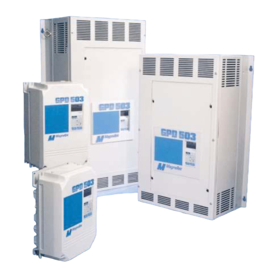
Summary of Contents for Magnetek gpd 503
- Page 1 Magne Tek GPD 503 Technical Manual...
- Page 2 This procedure will quickly get you up and running by Digital Operator keypad or user supplied remote operator control. It assumes that the GPD 503 and motor are correctly wired (see pages 1-8 thru 1-15), and start-up is to be performed without any changes to factory set constants.
- Page 3 (REAR VIEW) Shield wire SHIELD STOP termination WIRES Trim Pot 11 12 13 14 15 16 17 25 26 27 GPD 503 Control Board terminals 1 2 3 4 5 6 7 8 21 22 "Jumper wire" - ii -...
- Page 4 IMPORTANT: Programming is required to set up the drive for operation from external terminals. 6. Replace cover, make sure remote switch S1 is in “Stop” position, then apply power. Note that the DRIVE lamp is on. Press DRIVE/PROGRAM key, noting the DRIVE lamp goes out, indicating drive is in the “Program mode”.
- Page 5 Sn-20 Sn-21 Cn-28 (1) Setting depends on GPD 503 rating. See Table A3-1. (2) Initial value is related to V/f curve selected by Sn-02 setting. (3) Motor rated current (Cn-09) is set at 100% level. Setting range: 10 to 200% of GPD 503 rated capacity.
- Page 6 Horsepower Range HORSEPOWER RATED MODEL INPUT CT (150% OL) VT (125% OL) DS305 DS302 DS306 DS307 7.5/10 DS308 DS309 DS310 DS311 DS322 DS323 DS2040 40/50 GPD503-2L40 DS2050 GPD503-2L50 DS2060 GPD503-2L60 DS2075 GPD503-2L75 DS2100 GPD503-2L100 DS313 DS304 DS314 DS315 7.5/10 DS316 DS317 DS318 DS326...
- Page 7 For effective cooling as well as proper maintenance, a wall mount style GPD 503 must be installed vertically to the ground using four mounting screws. There MUST be a MINIMUM 6 in. clearance above and below the GPD 503. A MINIMUM 2 in. clearance is required on each side on the GPD 503.
- Page 8 • NEVER connect AC main power to output terminals T1 ( U ), T2 ( V ), and T3 ( W ). • NEVER allow wire leads to contact the GPD 503 enclosure. Short-circuit may result. • NEVER connect power factor correction capacitors or noise filter to GPD 503 output.
- Page 9 Table 1-1. Wire Sizing For Main Circuit SECTION A. 230V WIRE SIZE DRIVE TERMINAL TERMINAL WIRE SIZE TERMINAL SYMBOL mm 2 MODEL NO. SCREW RATING TERMINAL SYMBOL SCREW DS305 L1 (R), L2 (S), L3 (T), –, B1/+, B2, T1 (U), T2 (V), T3 (W), G (E) 14 - 10 2 - 5.5 DS302,...
- Page 10 Table 1-1. Wire Sizing For Main Circuit - Continued Section B. 460V WIRE SIZE DRIVE TERMINAL DRIVE TERMINAL WIRE SIZE TERMINAL SYMBOL MODEL NO. mm 2 mm 2 SCREW MODEL NO. TERMINAL SYMBOL SCREW DS313, DS304, L1 (R), L2 (S), L3 (T), –, B1/+, B2, T1 (U), T2 (V), T3 (W), G (E) 14 - 10 2 - 5.5 DS314...
- Page 11 Table 1-1. Wire Sizing For Main Circuit - Continued Section C. 575V WIRE SIZE DRIVE TERMINAL DRIVE TERMINAL WIRE SIZE TERMINAL SYMBOL MODEL NO. mm 2 mm 2 SCREW MODEL NO. TERMINAL SYMBOL SCREW DS5003, L1 (R), L2 (S), L3 (T), –, B1/+, B2, T1 (U), T2 (V), T3 (W) 14 - 10 2 - 5.5 DS5004...
- Page 12 Table 1-2. Terminal Functions and Voltages of Main Circuit SECTION A. 230V SECTION A. 230V FUNCTION TERMINAL FUNCTION TERMINAL 1 HP 1 - 10HP (CT) 15 - 30HP (CT) 3 TO 40 HP 40 - 100HP (CT) L1 (R) Three phase Main circuit input power supply L2 (S) 200 / 208 / 220V at 50 Hz;...


Need help?
Do you have a question about the gpd 503 and is the answer not in the manual?
Questions and answers