
Related Manuals for Endress+Hauser Smartec CLD18


Summary of Contents for Endress+Hauser Smartec CLD18
-
Page 1: Operating Instructions
Products Solutions Services BA01149C/07/EN/04.16 71314731 Operating Instructions Smartec CLD18 Conductivity measuring system... -
Page 3: Table Of Contents
......25 Calibration (Calibration menu) ..30 Endress+Hauser... -
Page 4: Document Information
Document information Smartec CLD18 Document information Warnings Structure of information Meaning This symbol alerts you to a dangerous situation. DANGER Failure to avoid the dangerous situation will result in a fatal or serious injury. Causes (/consequences) Consequences of non-compliance (if applicable) ‣... -
Page 5: Basic Safety Instructions
Smartec CLD18 Basic safety instructions Basic safety instructions Requirements for the personnel • Installation, commissioning, operation and maintenance of the measuring system may be carried out only by specially trained technical personnel. • The technical personnel must be authorized by the plant operator to carry out the specified activities. -
Page 6: Operational Safety
Basic safety instructions Smartec CLD18 Operational safety Before commissioning the entire measuring point, verify that all connections are correct. Ensure that electrical cables and hose connections are undamaged. Do not operate damaged products, and safeguard them to ensure that they are not operated inadvertently. -
Page 7: Incoming Acceptance And Product Identification
Smartec CLD18 Incoming acceptance and product identification Incoming acceptance and product identification Incoming acceptance Verify that the packaging is undamaged. Notify your supplier of any damage to the packaging. Keep the damaged packaging until the matter has been settled. -
Page 8: Scope Of Delivery
Enter the order code from the nameplate into the search field, and then select "Show details". You will receive information on each feature (selected option) of the order code. Scope of delivery The delivery comprises: • A Smartec CLD18 measuring system in the version ordered • Operating Instructions BA01149C/07/EN Endress+Hauser... -
Page 9: Certificates And Approvals
Smartec CLD18 Incoming acceptance and product identification Certificates and approvals 3.4.1 Declaration of Conformity The product meets the requirements of the harmonized European standards. As such, it complies with the legal specifications of the EC directives. The manufacturer confirms successful testing of the product by affixing to it the mark. -
Page 10: Product Description
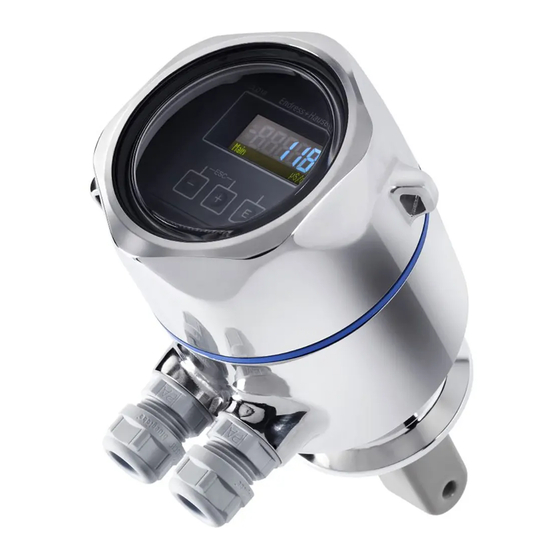
Product description Smartec CLD18 Product description A0019184 1 Elements Temperature sensor Process connection Leakage hole Removable housing cover Window for display Cable glands Flow opening of sensor Endress+Hauser... -
Page 11: Installation
Smartec CLD18 Installation Installation Installation conditions 5.1.1 Installation instructions For a 3-A compliant installation, the following must be noted: After the instrument is installed its hygienic integrity shall be maintained. The instrument shall be installed with the leakage detection at the lowest point of the assembly. - Page 12 Installation Smartec CLD18 The product should flow along the hole of the sensor (see the arrows on the housing). The symmetrical measuring channel allows flow in both directions. The ionic current in the liquid is affected by the walls in confined installation conditions.
- Page 13 Smartec CLD18 Installation 28 (1.10) 85 (3.35) (0.91) 112 (4.41) 28 (1.10) 85 (3.35) 5.2 (0.20) 20.5 (0.81) 114.5 (4.51) A0018942 5 Dimensions in mm (inch) and versions (examples) Endress+Hauser...
- Page 14 Installation Smartec CLD18 Plastic housing with thread G 1½ Stainless steel housing with ISO 2852 clamp 2" Stainless steel housing with Varivent DN 40 to 125 Plastic housing with coupling nut 2¼" PVC Endress+Hauser...
- Page 15 Smartec CLD18 Installation 5.1.2 Installation examples Ø 48.3 (1.90) Ø 44.3 (1.74) A0019302 6 Installation in DN 40 pipe with 2" Tri-Clamp process connection, dimensions in mm (inch) Endress+Hauser...
- Page 16 Installation Smartec CLD18 A0022166 7 Installation in DN 40 pipe with Varivent process connection, dimensions in mm (inch) Endress+Hauser...
-
Page 17: Mounting The Compact Device
Smartec CLD18 Installation Ø 40 (1.58) Ø 50 (1.97) A0024073 8 Installation in DN 40 pipe with coupling nut 2¼" PVC process connection, dimensions in mm (inch) Mounting the compact device Choose the installation depth of the sensor in the medium such that the coil body is completely immersed in the medium. -
Page 18: Electrical Connection
Electrical connection Smartec CLD18 Electrical connection WARNING Device is live Incorrect connection may result in injury or death ‣ The electrical connection may be performed only by an electrical technician. ‣ The electrical technician must have read and understood these Operating Instructions and must follow the instructions contained therein. - Page 19 Smartec CLD18 Electrical connection A0029684 10 Terminal assignment IOut1 Current output conductivity IOut2 Current output temperature Binary input (measuring range switch) Alarm output (open-collector) L+/L- Power supply Grounding pin (flat male tab 4.8 mm) Cover on electronics box Electronics box The recommended cable cross-section for the connecting cables is 0.5 mm...
-
Page 20: Ensuring The Degree Of Protection
Electrical connection Smartec CLD18 Ensuring the degree of protection Guarantee the degree of protection as follows: Check that the O-ring is seated correctly in the housing cover. Screw down the housing cover as far as it will go. Tighten the cable glands. -
Page 21: Operation Options
Smartec CLD18 Operation options Operation options Main µS/cm A0018963 11 Display and keys of the CLD18 Parameters Measured value Unit Operating keys The ASTN display (Advanced Super Twisted Nematic) is split into two sections. The segment section displays the measured value. The dot-matrix section displays the parameter and unit. -
Page 22: Operating Keys
Operation options Smartec CLD18 Operating keys • Open the Configuration menu • Confirm the entry • Select a parameter or submenu A0029236 Within the Configuration menu: • Gradually select the menu items / characters for the parameter • Change the selected parameter... -
Page 23: Menus
Perform sensor calibration* Diagnostics Device information, diagnostics logbook, sensor information, simulation * The air set and the correct cell constant have already been configured at the factory for Smartec CLD18 devices. A sensor calibration is not necessary during commissioning. Endress+Hauser... -
Page 24: Commissioning
Commissioning Smartec CLD18 Commissioning Switching on the device Familiarize yourself with the operation of the transmitter before it is first switched on. After power-up, the device performs a self-test and then goes to the measuring mode. If you are commissioning the device for the first time, program the setup as described in the following sections of the Operating Instructions. -
Page 25: Device Configuration (Setup Menu)
Smartec CLD18 Commissioning Device configuration (Setup menu) Press the ' E ' - key to call up the main menu. Navigate through the available menus with the ' + ' and ' – ' keys. Press the ' E ' - key to open the desired menu. Use the "x Back" option, which can be found at the bottom of each menu, to move up a level in the menu structure. - Page 26 Commissioning Smartec CLD18 Parameters Possible settings Description Inst. factor 0.1 to 5.0 The affect of the distance from the wall can be corrected with the installation factor (see the "Installation factor" section). Unit auto, μS/cm, mS/cm Unit of conductivity "auto" automatically switches between μS/cm and mS/cm.
- Page 27 Smartec CLD18 Commissioning Parameters Possible settings Description Damping main 0 ... 60 s Setting for the damping Alpha coeff. 1.0 to 20 %/K Coefficient for linear temperature compensation 2.1 %/K Factory default Factory settings Please confirm no, yes Endress+Hauser...
- Page 28 Commissioning Smartec CLD18 8.4.1 Installation factor In confined installation conditions, the conductivity measurement is affected by the pipe walls. The installation factor compensates for this effect. The cell constant is corrected by multiplying by the installation factor. The value of the installation factor depends on the diameter and the conductivity of the pipe nozzle as well as the sensor' s distance to the wall.
- Page 29 Smartec CLD18 Commissioning 8.4.2 Temperature compensation The conductivity of a liquid depends heavily on the temperature, as the mobility of the ions and the number of dissociated molecules are temperature-dependent. In order to compare measured values, they must be referenced to a defined temperature. The reference temperature is 25 °C (77 °F).
-
Page 30: Calibration (Calibration Menu)
The LOW and HIGH specifications are described in the "Technical data" section. Calibration (Calibration menu) The air set and the correct cell constant have already been configured at the factory for Smartec CLD18 devices. A sensor calibration is not necessary during commissioning. 8.5.1 Types of calibration The following types of calibration are possible: •... - Page 31 Smartec CLD18 Commissioning Calibrating the cell constant You enter a reference value for the conductivity with this type of calibration. In the result, the device calculates a new cell constant for the sensor. First switch off the temperature compensation: Select the "Setup" / "Extended setup" / "Input" / "Temp. comp:" menu.
- Page 32 Commissioning Smartec CLD18 8.5.3 Air set (residual coupling) While the calibration line goes through zero for physical reasons in the case of conductive sensors (a current flow of 0 corresponds to a conductivity of 0), when working with inductive sensors, the residual coupling between the primary coil (transmitter coil) and secondary coil (receiver coil) must be taken into account or compensated for.
-
Page 33: Diagnostics And Troubleshooting
Smartec CLD18 Diagnostics and troubleshooting Diagnostics and troubleshooting Trouble shooting instructions Press the ' E ' - key to call up the main menu. Navigate through the available menus with the ' + ' and ' – ' keys. Press the ' E ' - key to open the desired menu. Use the "x Back" option, which can be found at the bottom of each menu, to move up a level in the menu structure. -
Page 34: Diagnostic Messages
Diagnostics and troubleshooting Smartec CLD18 Diagnostic messages The diagnostic message consists of a diagnostic code and a message text. The diagnostic code consists of the error category as per Namur NE 107 and the message number. Error category (letter in front of the message number) •... - Page 35 Smartec CLD18 Diagnostics and troubleshooting Diagnostic code Message text Description F152 No airset Sensor data No calibration data available Remedy: Perform an air set F523 Cell const. Sensor calibration warning Invalid cell constant, max. range reached Remedy: • Enter cell constant as per factory specifications •...
- Page 36 Diagnostics and troubleshooting Smartec CLD18 Diagnostic code Message text Description S844 Process value Measured value outside the specified range Possible reasons: • Sensor in air • Incorrect flow to sensor • Sensor defective Remedy: • Increase process value • Check electrode system...
-
Page 37: Maintenance
The electronics box does not contain any parts that the user must maintain. • The cover on the electronics box may be opened only by Endress+Hauser Service staff. • The electronics box may be removed only by Endress+Hauser Service staff. -
Page 38: Repairs
The product must be returned if repairs or a factory calibration are required, or if the wrong product was ordered or delivered. As an ISO-certified company and also due to legal regulations, Endress+Hauser is obliged to follow certain procedures when handling any returned products that have been in contact with medium. -
Page 39: Accessories
Smartec CLD18 Accessories Accessories The following are the most important accessories available at the time this documentation was issued. For accessories not listed here, please contact your service or sales office. 12.1 Calibration solutions Conductivity calibration solutions CLY11 Precision solutions referenced to SRM (Standard Reference Material) by NIST for qualified calibration of conductivity measuring systems in accordance with ISO 9000 •... - Page 40 Technical data Smartec CLD18 13.1.4 Binary input The binary input is used for measuring range switching. Voltage range 0 V to 30 V Voltage HIGH min. 12 V Voltage LOW max. 9.0 V Current consumption at 24 V 30 mA Undefined voltage range 9.0 to 12 V...
-
Page 41: Power Supply
Smartec CLD18 Technical data 13.3 Power supply 13.3.1 Supply voltage 24 V DC ±20 %, protected against reverse polarity 13.3.2 Power consumption 13.3.3 Cable specification Recommendation 0.5 mm max. 1.0 mm 13.4 Performance characteristics 13.4.1 Response time Conductivity: t95 < 1.5 s Temperature: t90 <... - Page 42 Technical data Smartec CLD18 13.5 Environment 13.5.1 Ambient temperature range Stainless steel process connection: -20 to +60 °C (-4 to +140 °F) PVC process connection: -10 to +60 °C (14 to 140 °F) 13.5.2 Storage temperature Stainless steel process connection: -25 to +80 °C (-13 to +176 °F)
- Page 43 Smartec CLD18 Technical data 13.6 Process 13.6.1 Process temperature Stainless steel process connection: -10 to +110 °C (14 to 230 °F) Max.130 °C (266 °F) up to 60 minutes PVC process connection: -10 to +60 °C (14 to 140 °F) 13.6.2...
- Page 44 Technical data Smartec CLD18 13.6.3 Pressure-temperature ratings p (abs.) [psi] [bar] 188.5 130.5 14.5 [°C] T [°F] A0030822-EN 13 Pressure-temperature ratings Stainless steel process connection PVC process connection Process temperature increased briefly (max. 60 minutes) 13.6.4 Flow velocity max. 10 m/s (32.8 ft/s) for low-viscosity media in pipe DN 50...
- Page 45 Smartec CLD18 Technical data 13.7 Mechanical construction 13.7.1 Dimensions → Section "Installation" 13.7.2 Weight Stainless steel housing: up to 1.870 kg (4.12 lbs) Plastic housing: up to 1.070 kg (2.36 lbs) 13.7.3 Materials In contact with medium Sensor: PEEK (polyetheretherketone) Process connection: Stainless steel 1.4435 (AISI 316 L), PVC-U...
-
Page 46: Index
Menus ......23 MRS ......30 Endress+Hauser... - Page 48 *71314731* 71314731 www.addresses.endress.com...
Need help?
Do you have a question about the Smartec CLD18 and is the answer not in the manual?
Questions and answers