Do not proceed beyond a WARNING acquires no greater than Limited Rights as defined in FAR 27.401 or DFAR notice until the indicated conditions are 227.7103-5 (c), as applicable in any fully understood and met. technical data. N1911A/1912A P-Series Power Meters Programming Guide...
Keysight shall not be liable for errors or for incidental or consequential damages in connection with the furnishing, use, or performance of this document or any information contained herein.
For continued protection against fire hazard, replace the line fuse(s) only with fuses of the same type and rating (for example, normal blow, time delay, etc.). The use of other fuses or material is prohibited. N1911A/1912A P-Series Power Meters Programming Guide...
Failure to comply with these precautions or with specific warnings elsewhere in this manual violates safety standards of design, manufacture, and intended use of the instrument. Keysight Technologies assumes no liability for the customer’s failure to comply with these requirements.
Page 6
THIS PAGE HAS BEEN INTENTIONALLY LEFT BLANK. N1911A/1912A P-Series Power Meters Programming Guide...
....711 SERVice:SENSor[1]|2:FREQuency:MINimum? ....712 N1911A/1912A P-Series Power Meters Programming Guide...
Page 19
..........747 N1911A/1912A P-Series Power Meters Programming Guide...
Page 20
......760 Measurement Polling Example Measurement Polling Example using VEE program ....768 N1911A/1912A P-Series Power Meters Programming Guide...
..580 Figure 16-1 Measurement Display UNIT Block Window ..728 Figure B-1 Example of VEE program used in measurement polling N1911A/1912A P-Series Power Meters Programming Guide...
Page 22
THIS PAGE HAS BEEN INTENTIONALLY LEFT BLANK. N1911A/1912A P-Series Power Meters Programming Guide...
Settings ....... . .539 N1911A/1912A P-Series Power Meters Programming Guide...
Page 24
802.11a and HiperLan2: Power Meter Presets For Second- ary Channel Sensors ..... . . 567 N1911A/1912A P-Series Power Meters Programming Guide...
Page 26
Calibration Factor Block Layout: E4410 Series Sensors Table A-2 Calibration Factor Block Layout: E9300 Series Sensors Table A-3 Calibration Factor Block Layout: E9320 Series Sensors Table A-4 Calibration Factor Block Layout: N8480 Series Sensors N1911A/1912A P-Series Power Meters Programming Guide...
Page 27
N1911A/1912A P-Series Power Meters Programming Guide Power Meter Remote Operation Introduction Configuring the Remote Interface Zeroing and Calibrating the P-Series Power Sensor Making Measurement Using Frequency Dependent Offset Tables Setting the Range, Resolution and Averaging Range Configuring the Remote Interface...
– “An Introduction to the SCPI Language” on page 94. – “SCPI Compliance Information” on page 103. – “Summary of Commands” on page 105. – “Making Measurements on Wireless Communication Standards” on page 106. N1911A/1912A P-Series Power Meters Programming Guide...
Keysight Technologies USB/LAN/GPIB Interfaces Connectivity Guide. If you have installed the IO Libraries Suite, you can access the Connectivity Guide via the Keysight IO Libraries Control icon. Alternatively, you can access the Connectivity Guide via the Web at www.keysight.com/find/connectivity.
To individually specify the LAN settings, use the following commands: – IP Address -SYSTem:COMMuniucate:LAN:ADDRess – Subnet Mask -SYSTem:COMMunicate:LAN:SMASk – Default Gateway -SYSTem:COMMunicate:LAN:DGATeway – Domain Name -SYSTem:COMMunicate:LAN:DNAMe – Hostname -SYSTem:COMMunicate:LAN:HNAMe – Restart Network -SYSTem:COMMunicate:LAN:RESTart N1911A/1912A P-Series Power Meters Programming Guide...
Before connecting the USB cable, make sure that I/O software is installed on NOTE your computer. For more information about Keysight IO Libraries software refer to the NOTE Connectivity Guide. If you have installed other I/O Software, refer to documentation that accompanies the software.
– Prior to measuring low level signals. For example, 10 dB above the lowest specified power for your power sensor. Calibration The command used to calibrate the power meter is: CALibration[1|2]:AUTO ONCE It is recommended that you zero the power meter before calibrating. N1911A/1912A P-Series Power Meters Programming Guide...
Page 33
You can examine the Questionable Status Register or the error queue to discover if the sequence has passed or failed. Refer to “Status Reporting” on page 73 for further information. N1911A/1912A P-Series Power Meters Programming Guide...
1-1, the CONFigure command presets various states in the power meter. It may be likely that you do not want to preset these states. Refer to “Using the Lower Level Commands” on page 49 for further information. N1911A/1912A P-Series Power Meters Programming Guide...
(see Example 2 - Specifying the Source List Parameter), or defaults as in this example (see “Keysight N1912A Only” on page 38). N1911A/1912A P-Series Power Meters Programming Guide...
Page 36
The operation of the MEAS1? command when the source list parameter is defaulted is described in the note “Keysight N1912A Only” on page 38. For the N1911A it is not necessary to specify a channel as only one channel is NOTE available. Example 3 - Specifying the Expected Power Parameter The previous example details the three optional parameters which can be used with the MEASure? command.
Page 37
Note that as the source list parameter is the last specified parameter you do not have to specify DEF. The measurement is carried out on the upper window. specifies window specifies resolution setting MEAS1? DEF,3 N1911A/1912A P-Series Power Meters Programming Guide...
Page 38
(for example, A, B, A/B, A-B etc.) and on the particular command used (for example, MEAS[:POW][:AC]? and MEAS:POW:AC:RAT?). This means that when the source list parameter is defaulted, there are a number of possibilities. N1911A/1912A P-Series Power Meters Programming Guide...
Page 39
Current Window Setup Measurement Upper Window: MEAS1[:POW][AC]? Any Other Any Other Lower Window: MEAS2[:POW][AC]? Any Other Upper Window: MEAS1:POW:AC:RAT Any Other Lower Window: MEAS2:POW:AC:RAT Any Other Upper Window: MEAS1:POW:AC:DIFF? Any Other Lower Window: MEAS2:POW:AC:DIFF? Any Other N1911A/1912A P-Series Power Meters Programming Guide...
It is advisable to read through these examples in order as they become increasingly more detailed. These examples give an overview of the CONFigure command. For further information on the CONFigure commands refer to Chapter 2, "MEASurement Commands". N1911A/1912A P-Series Power Meters Programming Guide...
Page 41
Configure upper window -defaults to a Channel A measurement CONF1 Take upper window (Channel A) measurement READ1? Reset instrument *RST Configure lower window -defaults to a Channel A (N1911A), CONF2 Channel B (N1912A) measurement Take lower window measurement (Channel A on N1911A, READ2? B on N1912A)
Page 42
If they are defined they must be identical to those defined in the CONFigure command otherwise an error occurs. For the N1911A it is not necessary to specify a channel as only one channel is NOTE available.
Page 43
The resolution parameter is defaulted, leaving it at its current setting. The source list parameter specifies a Channel B measurement. The measurement is carried out on the upper window. N1911A/1912A P-Series Power Meters Programming Guide...
Page 44
Some fine tuning of measurements can be carried out using the CONFigure command and INITiate and FETCh? commands. For example, in the above program segment some fine tuning can be carried out by setting the filter length to 1024 and the trigger delay off. N1911A/1912A P-Series Power Meters Programming Guide...
Page 45
“Keysight N1912A Only” on page 38. Note that as the source list parameter is the last specified parameter you do not have to specify DEF. N1911A/1912A P-Series Power Meters Programming Guide...
Page 46
Causes Channel A to make a measurement INIT1 Retrieves the upper window’s measurement FETC1? DEF,3 Some fine tuning of the above program segment can be carried out for example, by setting the trigger delay off. 1 ABOR1 2 CONF1 DEF,3 N1911A/1912A P-Series Power Meters Programming Guide...
Page 47
CONF2:POW:AC:DIFF DEF,DEF,(@1),(@2) SENS1:AVER:COUN 1024 SENS2:AVER:COUN 1024 TRIG1:DEL:AUTO OFF TRIG2:DEL:AUTO OFF INIT1:IMM INIT2:IMM FETC2:POW:AC:DIFF? FETC2:POW:AC:DIFF? DEF,DEF,(@2),(@1) (A second FETCh? query is sent to make a Channel B -Channel A measurement using the current measurement data). N1911A/1912A P-Series Power Meters Programming Guide...
Page 48
Using INITiate and FETCh? ABOR1 ABOR2 CONF2:POW:AC:RAT DEF,DEF,(@1),(@2) SENS1:AVER:COUN 512 SENS2:AVER:COUN 256 INIT1:IMM INIT2:IMM FETC2:POW:AC:RAT? FETC2:POW:AC:RAT? DEF,DEF,(@2),(@1) (A second FETCh? query is sent to make a Channel B -Channel A measurement using the current measurement data.) N1911A/1912A P-Series Power Meters Programming Guide...
Sets lower range (E-Series sensors and N8480 SENS1:POW:AC:RANGE 0 Series sensors (excluding Option CFT) only) Sets the lower window’s resolution to setting 3 DISP:WIND2:RES 3 Causes Channel A to make a measurement INIT1 Retrieves the lower window’s measurement FETC2? N1911A/1912A P-Series Power Meters Programming Guide...
5 Specify the frequency of the signal you want to measure. The required offset is automatically set by the power meter from the frequency dependent offset table. 6 Make the measurement. Figure 1-1 illustrates how frequency dependent offset tables operate. N1911A/1912A P-Series Power Meters Programming Guide...
OFFSET FREQ OFFSET Frequency dependent Frequency of the signal you want offset used to make to measure Measurement. Calculated by the power meter using linear interpolation. FREQ OFFSET Figure 1-1 Frequency Dependent Offset Tables N1911A/1912A P-Series Power Meters Programming Guide...
" Frequency n Offset n 4 If required, rename the frequency dependent offset table using: MEMory:TABLe:MOVE <string>,<string>. The first <string> parameter identifies the existing table name, and the second identifies the new table name. N1911A/1912A P-Series Power Meters Programming Guide...
Page 53
Each string parameter returned indicates the name, type and size of a stored frequency dependent offset table: – <string>,<type>,<size> The <string>, <type> and <size> are all character data. The <type> is always TABL. The <size> is displayed in bytes. N1911A/1912A P-Series Power Meters Programming Guide...
Page 54
Query command which returns the offset factors stored in the frequency dependent offset table. Modifying Data If you need to modify the frequency and offset factor data stored in a frequency dependent offset table you need to resend the complete data lists. N1911A/1912A P-Series Power Meters Programming Guide...
Use either the INITiate, FETCh? or the READ? query to initiate the measurement as shown in the following program segments: INITiate Example ABORt1 CONFigure1:POWer:AC DEF,1,(@1) SENS1:CORR:CSET2:SEL "Offset1" SENS1:CORR:CSET2:STAT ON SENSe1:FREQuency 500KHZ INITiate1:IMMediate FETCh1? N1911A/1912A P-Series Power Meters Programming Guide...
Page 56
To find out the value of the offset being used by the power meter to make a measurement, use the query command: SENSe:CORRection:GAIN4|FDOFfset[:INPut][MAGNITUDE]? The response may be an interpolated value. N1911A/1912A P-Series Power Meters Programming Guide...
However, the time to take the measurement is increased. You can select the filter length or you can set the power meter to auto filter mode. To enable and disable averaging use the following command: [SENSe[1]]|SENSe2:AVERage[:STATe] <boolean> N1911A/1912A P-Series Power Meters Programming Guide...
Minimum Sensor Power 10 dB 10 dB 10 dB 10 dB Maximum Sensor Power Figure 1-2 Typical Averaged Readings on 8480 Series Sensors Figure 1-3 illustrates part of the power sensor dynamic range hysteresis. N1911A/1912A P-Series Power Meters Programming Guide...
The range of values for the filter length is 1 to 1024. Specifying this command disables automatic filter length selection. Increasing the value of the filter length reduces measurement noise. However, the time to take the measurement is increased. N1911A/1912A P-Series Power Meters Programming Guide...
For further information on this command refer to page 430. To enable autoranging use the following command: [SENSe[1]]|SENSe2:POWer:AC:RANGe:AUTO ON Use autoranging when you are not sure of the power level you will be measuring. N1911A/1912A P-Series Power Meters Programming Guide...
(refer to Figure 1-6 on page 72). Example The following example program, in HP Basic, details how to use the channel and display offsets on an N1912A making a Channel A/B ratio measurement. N1911A/1912A P-Series Power Meters Programming Guide...
Page 62
250 ENTER @Power;Reading 260 ! 270 PRINT "The measurement result is ";Reading;"dB." 280 END For further information on channel offsets refer to page 407. For further information on display offsets refer to page 182. N1911A/1912A P-Series Power Meters Programming Guide...
+90.00 dBm and the default lower limit is –90.00 dBm. A typical application for this feature is shown in Figure 1-4. Power Meter Swept Source Device Under Test CHANNEL A INPUT Figure 1-4 Limits Checking Application N1911A/1912A P-Series Power Meters Programming Guide...
100.0 p% 100.000 XW 1.000 aW 1.000 MW 1.000 pW Checking for Limit Failures There are two ways to check for limit failures: 1 Use the SENSe:LIMit:FAIL? and SENSe:LIMit:FCOunt? commands for channel limits or the N1911A/1912A P-Series Power Meters Programming Guide...
Page 65
0 if there have been no limit failures. In this case 1 is returned. Returns the total number of limit SENSe:LIMit:FCOunt? failures, in this case 2. Use the equivalent CALCulate commands for checking window limit failures. N1911A/1912A P-Series Power Meters Programming Guide...
SENSe or CALCulate, since you do not need to check the limit failures after every power measurement. Refer to “Status Reporting” on page 73 and “STATus Subsystem” on page 465 for further information. N1911A/1912A P-Series Power Meters Programming Guide...
E-Series sensors. Also, in FAST mode averaging, limits and ratio/difference math functions are disabled. Refer to “Specifications” in the P-Series Power Meters User’s Guide to see the influence of these speed settings on the accuracy and noise performance of the power meter. N1911A/1912A P-Series Power Meters Programming Guide...
Trigger, it takes a new measurement each time a trigger event is detected. A channel is in Triggered Free Run Continuous Trigger when INITiate:CONTinuous is set to ON and TRIGger:SOURce is not set to IMMediate. N1911A/1912A P-Series Power Meters Programming Guide...
Page 69
For example, with a filter length of 4 and SENS:SPE set to 20, approximately 5 readings/sec is calculated by the power meter. Typically, free run mode provides the best speed performance from the power meter (especially in 200 readings/sec mode). N1911A/1912A P-Series Power Meters Programming Guide...
FETCh command. For average only measurements a count of 4 is required, however, 10 is recommended. In normal mode (peak measurements) a count of 50 is required to attain 1000 readings per second. N1911A/1912A P-Series Power Meters Programming Guide...
The latter can be reduced using the FORMat REAL command to return results in binary format. The former is a combination of two factors: – the hardware platform being used – the programming environment being used N1911A/1912A P-Series Power Meters Programming Guide...
How Measurement are Calculated The MEASure commands in this figure can be replaced with the FETCh? and READ? commands. All references to Channel B in the above diagram refer to the N1912A only. NOTE N1911A/1912A P-Series Power Meters Programming Guide...
SCPI status system. This model consists of a condition register, a transition filter, an event register and an enable register. A set of these registers is called a status group. N1911A/1912A P-Series Power Meters Programming Guide...
It remains set until the event register is cleared; either when you read the register or when you send the *CLS (clear status) command. Event registers are read-only. N1911A/1912A P-Series Power Meters Programming Guide...
A small binary table shows the state of the chosen bit in each status register at the selected times T1 to T5. 0 0 0 0 0 0 Condition marks when event register is read Figure 1-8 Typical Status Register Bit Changes N1911A/1912A P-Series Power Meters Programming Guide...
This is not particularly efficient and there is a possibility that an event may be missed. For example on measurement polling, refer to Figure B-B-1 on page B-2. N1911A/1912A P-Series Power Meters Programming Guide...
– Enable your bus controller’s IEEE-488 SRQ interrupt Examples The following two examples are written in HP BASIC and illustrate possible uses for SRQ. In both cases, it is assumed that the power meter has been zeroed and calibrated. N1911A/1912A P-Series Power Meters Programming Guide...
Page 78
! Yes , read register ENTER @Pm;Event ! (this also clears it) OUTPUT @Pm;”STAT:DEV:COND?” ENTER @Pm;Cond IF Cond=0 THEN PRINT “Sensor disconnected” ELSE PRINT “Sensor connected” END IF END IF GOTO 170 ! Return to idle loop N1911A/1912A P-Series Power Meters Programming Guide...
Page 79
! Operation status bit set? OUTPUT @Pm;”STAT:OPER?”! Yes , read register ENTER @Pm;Oper ! (this also clears it) OUTPUT @Pm;”STAT:OPER:ULF?” ENTER @Pm;Ulf IF Ulf=2 THEN PRINT “Over limit detected” END IF GOTO 190 ! Return to idle loop N1911A/1912A P-Series Power Meters Programming Guide...
Page 80
Status and Questionable Status groups are 16 bits wide, while the Status Byte and Standard Event groups are 8 bits wide. In all 16-bit groups, the most significant bit (bit 15) is not used and is always set to 0. N1911A/1912A P-Series Power Meters Programming Guide...
Device Status Error/Event Queue Condition Event Enable Questionable Status Condition Event Enable Status Byte Output Queue RQS/MSS *STB? *SRE Standard Event Event Enable *ESR *ESE Operation Status Condition Event Enable Figure 1-9 Status System N1911A/1912A P-Series Power Meters Programming Guide...
Particular bits in the status byte register are cleared when: – The standard event, Questionable status, operation status and device status are queried. – The error/event queue becomes empty. – The output queue becomes empty. N1911A/1912A P-Series Power Meters Programming Guide...
Device Error A device error occurred, refer to error numbers 310 to 350 in the user’s guide. Execution Error An execution error occurred, refer to error numbers 211 to 241 in the user’s guide. N1911A/1912A P-Series Power Meters Programming Guide...
Page 84
STATus:QUEStionable:ENABle command to set the enable register mask. The questionable status model is shown in the pullout at the end of this chapter. The following bits in these registers are used by the power meter. N1911A/1912A P-Series Power Meters Programming Guide...
Error –231, ”Data questionable;Lower window log error” Error –231, ”Data questionable;Upper window log error” – CLEARED: When no errors are detected by the power meter during a measurement covering the causes given for it to set. N1911A/1912A P-Series Power Meters Programming Guide...
The following bits in these registers are used by the power meter: Table 1-9 Bit Definitions - Operation Status Bit Number Decimal Weight Definition CALibrating Summary 1 - 3 Not used MEASuring Summary Waiting for TRIGger Summary 6 - 9 Not used N1911A/1912A P-Series Power Meters Programming Guide...
– SET: If a measurement is made and either a channel or window upper limit test fails. – CLEARED: If a measurement is made and the upper limit test is not enabled or the test is enabled and passes. N1911A/1912A P-Series Power Meters Programming Guide...
Not used Channel A sensor connected Channel B sensor connected Channel A sensor error Channel B sensor error Channel A sensor Front/Rear Channel B sensor Front/Rear 16384 Front Panel key press [a] N1912A only N1911A/1912A P-Series Power Meters Programming Guide...
Front Panel Key Press This is an event, and DOES NOT set the condition register. The bit is set in the event register which is cleared when read. Note that the transition registers are of no use for this bit. N1911A/1912A P-Series Power Meters Programming Guide...
In GPIB mode only you can use a serial poll to check to see when bit 5 (standard event) is set in the status byte summary register. You could also configure the power meter for an SRQ interrupt by sending *SRE 32 (status byte enable register, bit 5). N1911A/1912A P-Series Power Meters Programming Guide...
Page 91
20 OUTPUT @Power;“*CLS” 30 OUTPUT @Power;“*ESE 1” 40 OUTPUT @Power;“CAL:AUTO ONCE;*OPC” 50 WHILE NOT BIT(SPOLL(@Power),5) 60 !(Computer carries out other operations here) 70 END WHILE 80 OUTPUT @Power;“MEAS:POW:AC?” 90 ENTER @Power;Result 100 PRINT Result 110 END N1911A/1912A P-Series Power Meters Programming Guide...
– The power meter’s input and output buffers are cleared. – The power meter is prepared to accept a new command string. For interfaces the that do not support a low-level device clear, use the ABORt NOTE command. N1911A/1912A P-Series Power Meters Programming Guide...
(for the specified root-level command) of the command tree. You must separate command mnemonics from each other using a colon. You can omit the leading colon if the command is the first of a new program line. N1911A/1912A P-Series Power Meters Programming Guide...
To avoid this, do not send a query command without reading the response. When you cannot avoid this situation, send a device clear before sending the second query command. N1911A/1912A P-Series Power Meters Programming Guide...
– Ovals enclose command mnemonics. The command mnemonic must be entered exactly as shown. – Dotted lines indicate an optional path for by passing secondary keywords. – Arrows and curved intersections indicate command path direction. N1911A/1912A P-Series Power Meters Programming Guide...
Throughout this document <character_data> is used to represent character data, that is, A -Z, a -z, 0 -9 and _ (underscore). For example: START and R6_5F. The format is defined as: <upper-case alpha> <upper-case alpha> <digit> Figure 1-11 Format of <character_data> N1911A/1912A P-Series Power Meters Programming Guide...
Page 98
Throughout this document <non-decimal numeric> is used to represent numeric information in bases other than ten (that is, hexadecimal, octal and binary). The following syntax diagram shows the standard for these three data structures. For examples, #HA2F, #ha4e, #Q62, #q15, #B01011. N1911A/1912A P-Series Power Meters Programming Guide...
Power Meter Remote Operation <digit> Figure 1-12 Format of <non-decimal numeric> Refer to section 7.7.4.1 of IEEE 488.2 for further details. N1911A/1912A P-Series Power Meters Programming Guide...
Throughout this document <NR2> numeric response data is defined as: digit digit Figure 1-14 Format of <NR2> For example: – 12.3 – +1.2345 – –0.123 Refer to section 8.7.3 of IEEE 488.2 for further details. N1911A/1912A P-Series Power Meters Programming Guide...
Throughout this document the decimal numeric element is abbreviated to <numeric_value>. For example, <NRf>, MINimum, MAXimum, DEFault or Not A Number (NAN). <string> Definition Throughout this document <string> is used to represent 7-bit ASCII characters. N1911A/1912A P-Series Power Meters Programming Guide...
A <carriage return> followed by a <newline> is also accepted. Many programming languages allow you to specify a message terminator character or EOI state to be automatically sent with each bus transaction. Message termination always sets the current path back to the root-level. N1911A/1912A P-Series Power Meters Programming Guide...
SCPI format in mind and they follow all of the syntax rules of the standard. CALibration[1|2]:RCALibration CALibration[1|2]:RCFactor DISPlay[:WINDow[1|2]]:FORMat DISPlay[:WINDow[1|2]]:METer:LOWer DISPlay[:WINDow[1|2]]:METer:UPPer DISPlay[:WINDow[1|2]]:RESolution DISPlay[:WINDow[1|2]]:SELect MEMory:CLEar[:NAME] MEMory:TABLe:SELect MEMory:STATe:DEFine MEMory:TABLe:GAIN[:MAGNitude] MEMory:TABLe:GAIN:POINts? MEMory:TABLe:MOVE [SENSe[1]]|SENSe2:AVERage:SDETect [SENSe[1]]|SENSe2:CORRection:CFACtor [SENSe[1]]|SENSe2:CORRection:DCYCle [SENSe[1]]|SENSe2:CORRection:FDOFfset [SENSe[1]]|SENSe2:SPEed [SENSe[1]]|SENSe2:POWer:AC:RANGe SERVice:SENSor[1|2]:CDATE? SERVice:SENSor[1|2]:CPLace? SERVice:SENSor[1|2]:SNUMber? SERVice:SENSor[1|2]:TYPE? SYSTem:COMMunicate:LAN:AIP SYSTem:COMMunicate:LAN:CURRent:ADDRess? SYSTem:COMMunicate:LAN:CURRent:DGATeway? N1911A/1912A P-Series Power Meters Programming Guide...
Page 104
Power Meter Remote Operation SYSTem:COMMunicate:LAN:CURRent:DNAMe? SYSTem:COMMunicate:LAN:CURRent:SMASk? SYSTem:COMMunicate:LAN:ADDRess SYSTem:COMMunicate:LAN:DGATeway SYSTem:COMMunicate:LAN:DHCP SYSTem:COMMunicate:LAN:HNAMe SYSTem:COMMunicate:LAN:RESTart SYSTem:COMMunicate:LAN:SMASk SYSTem:LOCal SYSTem:REMote SYSTem:RWLock UNIT[1|2]:POWer:RATio N1911A/1912A P-Series Power Meters Programming Guide...
This Guide details the commands available for both the N1911A and the N1912A NOTE power meters. As the N1911A is a single channel power meter only Channel A can be selected. Where instances of channel selection are detailed in this document they are only relevant for the N1912A.
580 for greater detail. – IDEN -See “iDEN” on page 584 for greater detail. – DVB -See “DVB” on page 588 for greater detail. – HIPERLAN2 -See “802.11a and HiperLan2” on page 565 for greater detail. N1911A/1912A P-Series Power Meters Programming Guide...
30 :SYST:ERR? <read string> !The system error query should !return “0: No Error” 40 SERV:SENS:TYPE? !The sensor type query should return one !of the following:E9321A|E9322A|E9323A|E9325A|E9326A|E9327A| !N1921A|N1922A The GSM setup is only valid with these !sensors 50 SYSTem:PRESet “GSM900” N1911A/1912A P-Series Power Meters Programming Guide...
Page 108
Power Meter Remote Operation THIS PAGE HAS BEEN INTENTIONALLY LEFT BLANK. N1911A/1912A P-Series Power Meters Programming Guide...
Page 110
MEASure[1]|2|3|4[:SCALar][:POWer:AC]:DIFFerence? [<expected_value>[,<resolution>[,<source list>]]] MEASure[1]|2|3|4[:SCALar][:POWer:AC]:DIFFerence: RELative? [<expected_value>[,<resolution>[,<source list>]]] MEASure[1]|2|3|4[:SCALar][:POWer:AC]:RATio? [<expected_value>[,<resolution>[,<source list>]]] MEASure[1]|2|3|4[:SCALar][:POWer:AC]:RATio:RELative? [<expected_value>[,<resolution>[,<source list>]]] This chapter explains how to use the MEASure group of instructions to acquire data using a set of high level instructions. N1911A/1912A P-Series Power Meters Programming Guide...
Chapter 14, “TRIGger Subsystem,” on page 639. The CONFigure, FETCh?, READ? and MEASure? commands all have a numeric suffix which refers to a specific window/measurement. Figure 2-1 shown an example of the configuration returned result windows. N1911A/1912A P-Series Power Meters Programming Guide...
If the current setting of the power sensor’s range is no longer valid for the new measurement, specifying the expected power value decreases the time taken to obtain a result. N1911A/1912A P-Series Power Meters Programming Guide...
Page 113
– Whether the calculation is A/B or B/A, for a ratio measurement. Entering a <source list> is only required if you are using an N1912A. As the N1911A has a single channel only, the source list can only be Channel A. The following commands are described in this chapter:...
Page 117
DISPlay:WINDow:RESolution?. The format of the return is <NR1> in the range 1 through 4. Example This command queries the current CONF2? configuration of the lower window/upper measurement. Reset Condition On reset: The command function is set to :POWer:AC. N1911A/1912A P-Series Power Meters Programming Guide...
Page 118
The expected power level is set to +20 dBm. The resolution is set to 3. The source list on the N1911A is set to Channel A on both windows and their measurements. The source list on the N1912A is set to Channel A for the upper measurement on both windows and Channel B for the lower measurement on both windows.
When TRIG:SOUR is set to BUS or HOLD, sets the power meter TRIGger:SOURce IMMediate to make the measurement immediately a trigger is received. Enables automatic delay before making the measurement. TRIGger:DELay:AUTO ON Enables automatic filter length selection. SENSE:AVERage:COUNt:AUTO ON Enables averaging. SENSE:AVERage:STATe ON N1911A/1912A P-Series Power Meters Programming Guide...
W. The default units are defined by UNIT:POWer. resolution A numeric value for the resolution. If unspecified the current 1 to 4 resolution setting is used. 1.0, 0.1, 0.01, 0.001 N1911A/1912A P-Series Power Meters Programming Guide...
Page 121
1 to 4 represents of 1, 0.1, 0.01 and 0.001 respectively. [c] N1912A only. Example This command configures the upper CONF1:POW:AC DEF,2,(@1) window/upper measurement to measure the power of Channel A, using the current sensor range and a resolution setting of 2. N1911A/1912A P-Series Power Meters Programming Guide...
W. The default units are defined by UNIT:POWer. resolution A numeric value for the resolution. If unspecified the 1 to 4 current resolution setting is used. 1.0, 0.1, 0.01, 0.001 N1911A/1912A P-Series Power Meters Programming Guide...
Page 123
[c] N1912A only. Example This command configures the lower CONF2:REL -50DBM,3,(@1) window/upper measurement to measure the relative power of Channel A, using an expected power level of –50 dBm and a resolution setting of 3. N1911A/1912A P-Series Power Meters Programming Guide...
[a] The mnemonic DEF means DEFault. This is not equivalent to the DEFault parameter used in the command sub-systems. The parameters must be entered in the specified order. If parameters are omitted, they default from the right. The parameter DEFault is used as a place holder. Specifying DEF leaves teh parameter value unchanged. N1911A/1912A P-Series Power Meters Programming Guide...
Page 125
[c] N1912A only. Example This command configures the lower CONF2:DIFF DEF,1,(@2),(@1) window/upper measurement to make a difference measurement of Channel B -Channel A, using the current sensor range and a resolution of 1 on both channels. N1911A/1912A P-Series Power Meters Programming Guide...
(@1),(@2) If unspecified and the current window setup is a (@2),(@1) source list difference measurement then this difference setup is (@1),(@1) used, otherwise it defaults to Channel A-B (N1912A) or (@2),(@2) A-A (N1911A). N1911A/1912A P-Series Power Meters Programming Guide...
Page 127
This command configures the upper CONF1:DIFF:REL DEF,1, window/upper measurement to make a (@1),(@2) difference measurement of Channel A -Channel B with relative mode on, using the current sensor range and a resolution of 1 on both channels. N1911A/1912A P-Series Power Meters Programming Guide...
[a] The mnemonic DEF means DEFault. This is not equivalent to the DEFault parameter used in the command sub-systems. The parameters must be entered in the specified order. If parameters are omitted, they default from the right. The parameter DEFault is used as a place holder. Specifying DEF leaves the parameter value unchanged. N1911A/1912A P-Series Power Meters Programming Guide...
Page 129
This command configures the upper CONF1:RAT DEF,4,(@1),(@2) window/upper measurement to make a ratio measurement of Channel A over Channel B, using the current sensor range and a resolution setting of 4 on both channels. N1911A/1912A P-Series Power Meters Programming Guide...
(@1),(@2) calculate the ratio. (@2),(@1) If unspecified and the current window setup is a ratio (@1),(@1) measurement then this ratio setup is used, otherwise it (@2),(@2) defaults to Channel A/B (N1912A) or A/A (N1911A). N1911A/1912A P-Series Power Meters Programming Guide...
Page 131
This command configures the upper CONF1:RAT:REL window/upper measurement to make a DEF,1,(@1),(@2) ratio measurement of Channel A over Channel B with relative mode on, using the current sensor range and a resolution setting of 1 on both channels. N1911A/1912A P-Series Power Meters Programming Guide...
To unlock the power meter and adjust trigger settings, an SDC (Selected Device Clear) GPIB Command must be performed. This is equivalent to “EXECUTE CLEAR” in Keysight VEE. N1911A/1912A P-Series Power Meters Programming Guide...
A numeric value for the resolution. If it is unspecified the 1 to 4 current resolution setting is used. If a value is entered it should 1.0, 0.1, 0.01, 0.001 correspond to the current resolution setting otherwise an error occurs. N1911A/1912A P-Series Power Meters Programming Guide...
Page 134
– If the expected_value and resolution parameters are not the same as the current expected value and resolution setting on the specified window, error –221, “Settings conflict” occurs. N1911A/1912A P-Series Power Meters Programming Guide...
A numeric value for the resolution. If it is unspecified the current 1 to 4 resolution setting is used. If a value is entered it should 1.0, 0.1, 0.01, 0.001 correspond to the current resolution setting otherwise an error occurs. N1911A/1912A P-Series Power Meters Programming Guide...
Page 136
– If the expected_value and resolution parameters are not the same as the current expected value and resolution settings on the specified window, error –221, “Settings conflict” occurs. N1911A/1912A P-Series Power Meters Programming Guide...
A numeric value for the resolution. If it is unspecified the 1 to 4 current resolution setting is used. If a value is entered it 1.0, 0.1, 0.01, 0.001 should correspond to the current resolution setting otherwise an error occurs. N1911A/1912A P-Series Power Meters Programming Guide...
Page 138
(@2),(@2) defaults to Channel A-B (N1912A) or A-A (N1911A). [a] The mnemonic DEF means DEFault. This is not equivalent to the DEFault parameter used in the command sub-systems. The parameters must be entered in the specified order.
A numeric value for the resolution. If it is unspecified the 1 to 4 current resolution setting is used. If a value is entered it 1.0, 0.1, 0.01, 0.001 should correspond to the current resolution setting otherwise an error occurs. N1911A/1912A P-Series Power Meters Programming Guide...
Page 140
(@2),(@2) defaults to Channel A-B (N1912A) or A-A (N1911A). [a] The mnemonic DEF means DEFault. This is not equivalent to the DEFault parameter used in the command sub-systems. The parameters must be entered in the specified order.
A numeric value for the resolution. If it is unspecified the 1 to 4 current resolution setting is used. If a value is entered it 1.0, 0.1, 0.01, 0.001 should correspond to the current resolution setting otherwise an error occurs. N1911A/1912A P-Series Power Meters Programming Guide...
Page 142
(@2),(@2) defaults to Channel A/B (N1912A) or A/A (N1911A). [a] The mnemonic DEF means DEFault. This is not equivalent to the DEFault parameter used in the command sub-systems. The parameters must be entered in the specified order.
A numeric value for the resolution. If it is unspecified the 1 to 4 current resolution setting is used. If a value is entered it should resolution 1.0, 0.1, 0.01, 0.001 correspond to the current resolution setting otherwise an error occurs. N1911A/1912A P-Series Power Meters Programming Guide...
Page 144
(@2),(@2) defaults to Channel A/B (N1912A) or A/A (N1911A). [a] The mnemonic DEF means DEFault. This is not equivalent to the DEFault parameter used in the command sub-systems. The parameters must be entered in the specified order.
The format of the result is set by FORM[:READ][:DATA]. Refer to Chapter 6, “FORMat Subsystem,” on page 261 for further information. – For the N1911A the READ? query is equivalent to: ABORt INITiate FETCh? –...
The expected power level parameter can be set to DEF or a sensor dependent (for the expected power level) numeric value. If a value is entered it should correspond to that set by CONFigure otherwise an error occurs. N1911A/1912A P-Series Power Meters Programming Guide...
Page 147
– If TRIGger:SOURce is set to BUS or HOLD, error –214, “Trigger deadlock” occurs. – If the expected value and resolution parameters are not the same as the current expected value and resolution settings on the specified window, error –221, “Settings conflict” occurs. N1911A/1912A P-Series Power Meters Programming Guide...
INITiate:CONTinuous must be set to OFF, otherwise error –213, “INIT ignored” NOTE occurs. If TRIGger:SOURce is set to BUS, error –214, “Trigger deadlock” occurs. Syntax READ :POW :REL :SCAL Space expected_value resolution source list N1911A/1912A P-Series Power Meters Programming Guide...
Page 149
Specifying DEF leaves the parameter value unchanged. [b] When the measurement result is linear this parameter represents the number of significant digits. When the measurement result is logarithmic 1 to 4 represents of 1, 0.1, 0.01 and 0.001 respectively. N1911A/1912A P-Series Power Meters Programming Guide...
Page 150
– If TRIGger:SOURce is set to BUS or HOLD, error –214, “Trigger deadlock” occurs. – If the expected value and resolution parameters are not the same as the current expected value and resolution settings on the specified window, error –221, “Settings conflict” occurs. N1911A/1912A P-Series Power Meters Programming Guide...
A numeric value for the resolution. If it is unspecified the current 1 to 4 resolution setting is used. If a value is entered it should correspond 1.0, 0.1, 0.01, 0.001 to the current resolution setting otherwise an error occurs. N1911A/1912A P-Series Power Meters Programming Guide...
Page 152
(@2),(@2) defaults to Channel A-B (N1912A) or A-A (N1911A). [a] The mnemonic DEF means DEFault. This is not equivalent to the DEFault parameter used in the command sub-systems. The parameters must be entered in the specified order.
IINITiate:CONTinuous must be set to OFF on both channels, otherwise error NOTE –213, “INIT ignored” occurs. If TRIGger:SOURce is set to BUS on either channel, error –214, “Trigger deadlock” occurs. Syntax :DIFF :REL READ :POW :SCAL expected_value Space resolution source list N1911A/1912A P-Series Power Meters Programming Guide...
Page 154
(@2),(@2) defaults to Channel A-B (N1912A) or A-A (N1911A). [a] The mnemonic DEF means DEFault. This is not equivalent to the DEFault parameter used in the command sub-systems. The parameters must be entered in the specified order.
Page 155
– If TRIGger:SOURce is set to BUS or HOLD on either channel, error –214, “Trigger deadlock” occurs. – If the resolution parameter is not the same as the current resolution setting on the specified window, error –221, “Settings conflict” occurs. N1911A/1912A P-Series Power Meters Programming Guide...
A numeric value for the resolution. If it is unspecified the current 1 to 4 resolution setting is used. If a value is entered it should correspond 1.0, 0.1, 0.01, 0.001 to the current resolution setting otherwise an error occurs. N1911A/1912A P-Series Power Meters Programming Guide...
Page 157
(@1),(@1) Channel A/B (N1912A) or A/A (N1911A). (@2),(@2) [a] The mnemonic DEF means DEFault. This is not equivalent to the DEFault parameter used in the command sub-systems. The parameters must be entered in the specified order.
IINITiate:CONTinuous must be set to OFF on both channels, otherwise error NOTE –213, “INIT ignored” occurs. If TRIGger:SOURce is set to BUS on either channel, error –214, “Trigger deadlock” occurs. Syntax READ :REL :RAT :SCAL :POW expected_value Space resolution source list N1911A/1912A P-Series Power Meters Programming Guide...
Page 159
[b] When the measurement result is linear this parameter represents the number of significant digits. When the measurement result is logarithmic 1 to 4 represents of 1, 0.1, 0.01 and 0.001 respectively. [c] N1912A only. N1911A/1912A P-Series Power Meters Programming Guide...
Page 160
– If TRIGger:SOURce is set to BUS or HOLD on either channel, error –214, “Trigger deadlock” occurs. – If the resolution parameter is not the same as the current resolution setting on the specified window, error –221, “Settings conflict” occurs. N1911A/1912A P-Series Power Meters Programming Guide...
Chapter 6, “FORMat Subsystem,” on page 261 for further information. MEASure? is a compound command which is equivalent to: – For the N1911A the MEASure? query is equivalent to: ABORt CONFigure READ? – For the N1912A carrying out a single channel measurement the MEASure?
If unspecified the current window setup is used. However, on (@2) (N1912A only) the N1912A, if the window shows a ratio or difference measurement, the upper window defaults to Channel A and the lower window to Channel B. N1911A/1912A P-Series Power Meters Programming Guide...
Page 163
1 to 4 represents of 1, 0.1, 0.01 and 0.001 respectively. Example This command queries the lower window/ MEAS2:POW:AC? -70DBM,1,(@1) upper measurement of Channel A, using an expected power level of -70 dBm and a resolution setting of 1. N1911A/1912A P-Series Power Meters Programming Guide...
W. The default units are defined by level) UNIT:POWer. resolution A numeric value for the resolution. If unspecified the current 1 to 4 resolution setting is used. 1.0, 0.1, 0.01, 0.001 N1911A/1912A P-Series Power Meters Programming Guide...
Page 165
1 to 4 represents of 1, 0.1, 0.01 and 0.001 respectively. Example This command queries the upper window/ MEAS1:REL? -50DBM,2,(@2) upper measurement relative measurement of Channel B, using an expected power level of –50 dBm and a resolution setting of 2. N1911A/1912A P-Series Power Meters Programming Guide...
(for the expected power parameter. Any value entered is treated like DEF. level) resolution A numeric value for the resolution. If unspecified the current 1 to 4 resolution setting is used. 1.0, 0.1, 0.01, 0.001 N1911A/1912A P-Series Power Meters Programming Guide...
Page 167
(@2),(@2) defaults to Channel A-B (N1912A) or A-A (N1911A). [a] The mnemonic DEF means DEFault. This is not equivalent to the DEFault parameter used in the command sub-systems. The parameters must be entered in the specified order.
(for the expected power parameter. Any value entered is treated like DEF. level) resolution A numeric value for the resolution. If unspecified the current 1 to 4 resolution setting is used. 1.0, 0.1, 0.01, 0.001 N1911A/1912A P-Series Power Meters Programming Guide...
Page 169
(@2),(@2) defaults to Channel A-B (N1912A) or A-A (N1911A). [a] The mnemonic DEF means DEFault. This is not equivalent to the DEFault parameter used in the command sub-systems. The parameters must be entered in the specified order.
(for the expected power parameter. Any value entered is treated like DEF. level) resolution A numeric value for the resolution. If unspecified the current 1 to 4 resolution setting is used. 1.0, 0.1, 0.01, 0.001 N1911A/1912A P-Series Power Meters Programming Guide...
Page 171
(@2),(@2) defaults to Channel A/B (N1912A) or A/A (N1911A). [a] The mnemonic DEF means DEFault. This is not equivalent to the DEFault parameter used in the command sub-systems. The parameters must be entered in the specified order.
(for the expected power parameter. Any value entered is treated like DEF. level) resolution A numeric value for the resolution. If unspecified the current 1 to 4 resolution setting is used. 1.0, 0.1, 0.01, 0.001 N1911A/1912A P-Series Power Meters Programming Guide...
Page 173
(@2),(@2) to Channel A/B (N1912A) or A/A (N1911A). [a] The mnemonic DEF means DEFault. This is not equivalent to the DEFault parameter used in the command sub-systems. The parameters must be entered in the specified order.
Page 174
MEASurement Commands THIS PAGE HAS BEEN INTENTIONALLY LEFT BLANK. N1911A/1912A P-Series Power Meters Programming Guide...
Measurement Display CALCulate Block Window Data from both SENSe blocks may feed any or all of the CALCulate blocks via the MATH command. Figure 3-1 details where the commands are applied with in the CALCulate block. N1911A/1912A P-Series Power Meters Programming Guide...
For example, if one feed is changed to PTAV, the other is automatically changed to PTAV. Under certain circumstances the measurement mode is changed by the CALC:MATH:EXPR command. Refer to “CALCulate[1]|2|3|4:MATH[:EXPRession] <string>” on page 201 for further information. Syntax Space string CALC :FEED N1911A/1912A P-Series Power Meters Programming Guide...
Page 180
2. The channel from which the feed is taken is determined by CALC:MATH:EXPR.. Reset Condition On reset, data_handle is set to :POW:AVER. Query CALCulate[1]|2|3|4:FEED[1]2? The query returns the current value of the string. N1911A/1912A P-Series Power Meters Programming Guide...
Page 181
– If the command changes the measurement mode to PEAK or PTAV when a sensor other than a P-Series or E9320 power sensor is connected or a P-Series or E9320 Sensor is connected and set to AVERage mode rather than NORMal mode, error –221, “Settings Conflict” occurs. N1911A/1912A P-Series Power Meters Programming Guide...
These commands are used to enter and enable a display offset on the specified window/measurement. The display offset is applied to the measurement signal after any math calculation. The following commands are detailed in this section: CALCulate[1]|2|3|4:GAIN[:MAGNitude] <numeric value> CALCulate[1]|2|3|4:GAIN:STATe <boolean> N1911A/1912A P-Series Power Meters Programming Guide...
Item Description/Defaul t Range of Values numeric_value A numeric value for the display offset: –100.000 to +100.000 dB – DEF: the default value is 0 dB – MIN: –100.000 dB – MAX: +100.000 dB N1911A/1912A P-Series Power Meters Programming Guide...
Page 184
This command queries the current setting CALC1:GAIN? of the display offset on the upper window/ upper measurement. Error Message If CALCulate[1]|2|3|4:GAIN[:MAGNitude] is set to ON while SENSe:SPEed is set to 200, error –221, “Settings Conflict” occurs. N1911A/1912A P-Series Power Meters Programming Guide...
The query enters a 1 or 0 into the output buffer indicating the status of the display offset. – 1 is returned when the display offset feature is enabled – 0 is returned when the display offset feature is disabled N1911A/1912A P-Series Power Meters Programming Guide...
Page 186
This command queries whether the display CALC1:GAIN:STAT? offset in the upper window/upper measurement is on or off. Error Message If CALCulate[1]|2|3|4:GAIN:STATe is set to ON while SENSe:SPEed is set to 200, error –221, “Settings Conflict” occurs. N1911A/1912A P-Series Power Meters Programming Guide...
– Query if there has been a failure – Count the number of failures – Clear the counter The following commands are detailed in this section: CALCulate[1]|2|3|4:LIMit:CLEar:AUTo <boolean> CALCulate[1]|2|3|4:LIMit:CLEar[IMMediate] CALCulate[1]|2|3|4:LIMit:FAIL? CALCulate[1]|2|3|4:LIMit:FCOunt? CALCulate[1]|2|3|4:LIMit:LOWer[:DATA] CALCulate[1]|2|3|4:LIMit:UPPer[:DATA] CALCulate[1]|2|3|4:LIMit:STATe <boolean> N1911A/1912A P-Series Power Meters Programming Guide...
– If OFF is specified, the FCO is not cleared by the above commands. – If ONCE is specified, the FCO is cleared only after the first initialization then starts accumulating any limit failures. Syntax 0|OFF Space :AUTO CALC :LIM :CLE 1|ON ONCE N1911A/1912A P-Series Power Meters Programming Guide...
Page 189
If a measurement is initiated then 0 is entered. Query Example This command queries when the FCO is CALC1:LIM:CLE:AUTO? cleared for the upper window/upper measurement. N1911A/1912A P-Series Power Meters Programming Guide...
This command immediately clears the FCO (fail counter) of any limit failures for the specified window. The FCO is used to determine the results returned by the CALCulate[1]|2|3|4:LIMit:FAIL? query. Syntax :CLE :IMM :LIM CALC Example This command clears the FCO for the lower CALC2:LIM:CLE:IMM window/upper measurement. N1911A/1912A P-Series Power Meters Programming Guide...
This command queries if there have been CALC1:LIM:FAIL? any limit failures on the upper window/ upper measurement. Reset Condition On reset, the buffer is set to zero for both upper and lower window measurements. N1911A/1912A P-Series Power Meters Programming Guide...
– read using READ? – initiated using: – INITiate[:IMMediate] or, – INITiate:CONTinuous ON The maximum number of errors is 2 –1. If more than 2 –1 errors are detected the counter returns to zero. N1911A/1912A P-Series Power Meters Programming Guide...
Page 193
Example This command queries the number of limit CALC1:LIM:FCO? failures on the upper window/upper measurement. Reset Condition On reset, the counter is set to zero for both measurements of the upper and lower windows. N1911A/1912A P-Series Power Meters Programming Guide...
Measurement Units Measurement Mode Measurement Type CALC:REL:STAT OFF CALC:REL:STAT ON Linear Linear Single Channel Avg, Pk Watt Pk–Avg Ratio Avg, Pk, Pk–Avg Difference Avg, Pk Watt Pk–Avg Syntax Space numeric_value :LOW :DATA CALC :LIM Space N1911A/1912A P-Series Power Meters Programming Guide...
Page 195
The query returns the current setting of the lower limit or the values associated with MIN and MAX for the specified window. Query Example This command queries the lower limit set CALC2:LIM:LOW:DATA? for the lower window upper measurement. N1911A/1912A P-Series Power Meters Programming Guide...
Measurement Units Measurement Mode Measurement Type CALC:REL:STAT OFF CALC:REL:STAT ON Linear Linear Single Channel Avg, Pk Watt Pk–Avg Ratio Avg, Pk, Pk–Avg Difference Avg, Pk Watt Pk–Avg Syntax Space numeric_value :DATA :LIM :UPP CALC Space N1911A/1912A P-Series Power Meters Programming Guide...
Page 197
This command queries the setting of the CALC2:LIM:UPP:DATA? upper limit for the lower window/upper measurement. The query returns the current setting of the upper limit or the values associated with MIN and MAX for the specified window/measurement. N1911A/1912A P-Series Power Meters Programming Guide...
The query enters 1 or 0 into the output buffer indicating the status of the limits testing feature for the specified window/measurement. – 1 is returned when limits testing is enabled – 0 is returned when limits testing is disabled N1911A/1912A P-Series Power Meters Programming Guide...
Page 199
This command queries whether the limit CALC1:LIM:STAT? checking function for the upper window/ upper measurement is on or off. Error Message If CALCulate[1|2|3|4]:LIMit:STATe is set to ON while [SENSe[1]]|SENSe2:SPEed is set to 200, error –221, “Settings Conflict” occurs. N1911A/1912A P-Series Power Meters Programming Guide...
CALCulate Subsystem CALCulate[1]|2|3|4:MATH Commands These commands define and carry out the following mathematical transformations on SENSe data: – Single channel – Difference – Ratio The following commands are detailed in this section: CALCulate[1]|2|3|4:MATH[:EXPRession] <string> CALCulate[1]|2|3|4:MATH[:EXPRession]:CATalog? N1911A/1912A P-Series Power Meters Programming Guide...
A single string value detailing the measurement type: “(SENS1)” – For the Keysight N1911A the default is SENS1. [a],[b] “(SENS2)” – For the Keysight N1912A the default is SENS1 if the upper [a],[c] “(SENS1–SENS1)” window is selected, or SENS2 if the lower window is [a],[b],[c] “(SENS2–SENS2)”...
Page 202
B/A ratio measurement. Reset Condition On reset, the Keysight N1911A upper and lower window measurements are set to Channel A ("(SENS1)"). On the N1912A the upper window measurements are set to Channel A ("(SENS1)") and the lower window measurements to Channel B ("(SENS2)").
Page 203
Error Messages – For the single channel N1911A power meter: if <string> is not set to “(SENS1)” while SENSe:SPEed is set to 200, error –221, “Settings Conflict” occurs. – For the dual channel N1912A power meter: if <string> is not set to “(SENS1)”...
CALCulate[1]|2|3|4:MATH[:EXPRession]:CATalog? This query lists all the defined expressions. The response is a list of comma separated strings. Each string contains an expression. – For the N1911A the string is: “(SENS1)”, “(SENS1–SENS1)”, “(SENS1/SENS1)” – For the N1912A the string is: "(SENS1)","(SENS2)","(SENS1/SENS2)", "(SENS2/SENS1)","(SENS1–SENS2)","(SENS2–SENS1)"...
– If a sensor, other than an P-Series or E9320 power sensor, is connected, error –241 “Hardware missing” occurs. – If SENS:DET:FUNC is set to AVER or TRIG:SOUR is set to INT1, INT2 or EXT, error –221 “Settings conflict” occurs. N1911A/1912A P-Series Power Meters Programming Guide...
These commands compare the measurement signal to a reference value. Within the CALCulate block the relative value is applied to the measurement signal after any math calculations and display offsets have been applied. The commands described in this section: CALCulate[1]|2|3|4:RELative[:MAGNitude]:AUTO <boolean>|ONCE CALCulate[1]|2|3|4:RELative:STATe <boolean> N1911A/1912A P-Series Power Meters Programming Guide...
OFF is only available because it is required for the query response. If 1|ON is selected, it causes error –224, “Illegal parameter value” to occur. Syntax Space :MAGN :AUTO 1|ON :REL CALC 0|OFF ONCE N1911A/1912A P-Series Power Meters Programming Guide...
Page 208
Error Message – If CALCulate:RELative[:MAGNitude]:AUTO is set to ONCE while SENSe:SPEed is set to 200, error –221, “Settings Conflict” occurs. – If the value is set to ON error –224, “Illegal parameter value” occurs. N1911A/1912A P-Series Power Meters Programming Guide...
On reset, relative mode is disabled. Query CALCulate[1]|2|3|4:RELative:STATe? The query returns a 1 or 0 into the output buffer. – 1 is returned when relative mode is enabled – 0 is returned when relative mode is disabled N1911A/1912A P-Series Power Meters Programming Guide...
Page 210
This command queries whether relative CALC1:REL:STAT? mode is off or on for the upper window/ upper measurement. Error Message If CALCulate:RELative:STATe is set to ON while SENSe:SPEed is set to 200, error –221, “Settings Conflict” occurs. N1911A/1912A P-Series Power Meters Programming Guide...
N1911A/1912A P-Series Power Meters Programming Guide CALibration Subsystem CALibration Subsystem CALibration[1]|2[:ALL] CALibration[1]|2[:ALL]? CALibration[1]|2:AUTO [ONCE|ON|OFF|0|1] CALibration[1]|2:RCALibration <boolean> CALibration[1]|2:RCFactor <numeric_value> CALibration[1]|2:ZERO:AUTO [ONCE|ON|OFF|0|1] CALibration[1]|2:ZERO:NORMal:AUTO <boolean> This chapter explains how the CALibration command subsystem is used to zero and calibrate the power meter.
– CALibration1 represents Channel A – CALibration2 represent Channel B This command does not apply to the single channel N1911A power meter and results in the error “Header suffix out of range.” Zeroing and calibration of the power meter is recommended: –...
CALibration:RCFactor?. E-Series power sensors and N8480 Series power sensors (excluding Option CFT) have their sensor calibration tables stored in EEPROM which means that the reference calibration factor is automatically downloaded by the power meter. N1911A/1912A P-Series Power Meters Programming Guide...
Page 215
– If zeroing was not carried out successfully the error –231, “Data Questionable; ZERO ERROR” occurs. If you are using an N1912A the error message specifies which channel failed calibration. – If there is no sensor connected, the error –241, “Hardware Missing” occurs. N1911A/1912A P-Series Power Meters Programming Guide...
The E-Series power sensors and N8480 Series power sensors (excluding Option CFT) have their sensor calibration tables stored in EEPROM which means that the reference calibration factor is automatically downloaded by the power meter. N1911A/1912A P-Series Power Meters Programming Guide...
Page 217
– If zeroing was not carried out successfully the error –231, “Data Questionable; ZERO ERROR” occurs. If you are using an N1912A the error message specifies which channel failed calibration. – If there is no sensor connected, the error –241, “Hardware Missing” occurs. N1911A/1912A P-Series Power Meters Programming Guide...
CALibration:RCFactor?. If the power meter is using an 8480, E-Series or N8480 Series power sensor it NOTE should be zeroed before calibration using the CALibration:ZERO:AUTO ONCE command. N1911A/1912A P-Series Power Meters Programming Guide...
Page 219
– If the calibration was not carried out successfully the error –231, “Data Questionable; CAL ERROR” occurs. If you are using an N1912A the error message specifies which channel failed calibration. – If there is no sensor connected, the error –241, “Hardware Missing” occurs. N1911A/1912A P-Series Power Meters Programming Guide...
Page 220
– If this command is set to ON (for dual channel, at either measurement channel) when a P-Series power sensor is connected (for dual channel, at either measurement channel) and is in the wait-for-trigger state for external trigger buffering, the error –224, “Illegal parameter value” occurs. N1911A/1912A P-Series Power Meters Programming Guide...
The query enters a 1 or 0 into the output buffer indicating whether zero/cal lockout is enabled or disabled. – 1 is returned if zero/cal lockout is enabled – 0 is returned if zero/cal lockout is disabled N1911A/1912A P-Series Power Meters Programming Guide...
Page 222
MEAS? etc) does not return a result and generates the error –230, “Data corrupt or stale; Please zero and Cal.” After the sensor has been zeroed and calibrated the return measurement results commands function normally. N1911A/1912A P-Series Power Meters Programming Guide...
Syntax Space numeric_value :RCF Space Parameters Item Description/Defaul t Range of Values numeric_value A numeric value: 1.0 to 150.0 PCT – DEF: the default is 100 % – MIN: 1 % – MAX:150 % N1911A/1912A P-Series Power Meters Programming Guide...
Page 224
This command queries the reference CAL2:RCF? calibration factor of Channel B. Error Messages If this command is used when a P-Series, E-Series or N8480 Series power sensors (excluding Option CFT) is connected the error –241, “Hardware missing” occurs. N1911A/1912A P-Series Power Meters Programming Guide...
Syntax Space :ZERO :AUTO 0|OFF 1|OFF ONCE Example This command causes the power meter to CAL2:ZERO:AUTO ONCE perform a zeroing routine on Channel B. Reset Condition On reset, automatic zeroing is disabled. N1911A/1912A P-Series Power Meters Programming Guide...
Page 226
– If there is no sensor connected, the error –241, “Hardware Missing” occurs. – If this command is set to ON and TRIGger[:SEQuence[1]|2]:COUNt setting is more than 1, the error –221, “Setting conflict” occurs. N1911A/1912A P-Series Power Meters Programming Guide...
Except when using a P-Series sensor, this command assumes that the E9320 Series sensor is not connected to a power source. Syntax Space :ZERO :NORM :AUTO 0|OFF ONCE Example This command causes the power meter to CAL2:ZERO:NORM:AUTO ONCE perform a zeroing routine on Channel B. N1911A/1912A P-Series Power Meters Programming Guide...
Page 228
– If there is no sensor connected, or if a sensor other than an E9320 or P-Series is connected, the error –241, “Hardware missing” occurs. – If an E9320 sensor is connected and is not in NORMAL mode, the error –221 “Settings conflict” occurs. N1911A/1912A P-Series Power Meters Programming Guide...
Page 229
N1911A/1912A P-Series Power Meters Programming Guide DISPlay Subsystem DISPlay Subsystem DISPlay:ENABle <boolean> DISPlay:SCReen:FORMat <character_data> DISPlay[:WINDow[1]|2] Commands DISPlay[:WINDow[1]|2]:ANALog Commands DISPlay[:WINDow[1]|2]:ANALog:LOWer <numeric_value> DISPlay[:WINDow[1]|2]:ANALog:UPPer <numeric_value> DISPlay[:WINDow[1]|2]:FORMat <character_data> DISPlay[:WINDow[1]|2]:METer Commands DISPlay[:WINDow[1]|2]:METer:LOWer <numeric_value> DISPlay[:WINDow[1]|2]:METer:UPPer <numeric_value> DISPlay[:WINDow[1]|2][:NUMeric[1]|2]:RESolution <numeric_value> DISPlay[:WINDow[1]|2]:SELect[1]|2 DISPlay[:WINDow[1]|2]:STATe <boolean> DISPlay[:WINDow[1]|2]:TRACe:FEED <character_data> This chapter explains how the DISPlay subsystem is used to control the selection...
The query returns a 1 or 0 into the output buffer. – 1 is returned when the display is enabled – 0 is returned when the display is disabled Query Example This command queries whether the display is DISP:ENAB? on or off. N1911A/1912A P-Series Power Meters Programming Guide...
The EXP display format provides access to softkeys. – FSCReen: the full screen format provides one display window which can display a single measurement. The FSCR display format does not provide access to softkeys. N1911A/1912A P-Series Power Meters Programming Guide...
Page 233
This command sets the display format to full DISP:SCReen:FORM FSCR screen. Reset Condition On reset, the display format is WIND. Query DISPlay:SCReen:FORMat? The query returns WIND, EXP or FSCR. . Query Example This command queries the display format. DISP:SCR:FORM? N1911A/1912A P-Series Power Meters Programming Guide...
WINDow2 represent the upper and lower windows respectively. The following commands are detailed in this section: DISPlay[:WINDow[1]|2]:ANALog:LOWer <numeric_value> DISPlay[:WINDow[1]|2]:ANALog:UPPer <numeric_value> DISPlay[:WINDow[1]|2]:FORMat <character_data> DISPlay[:WINDow[1]|2]:METer:LOWer <numeric_value> DISPlay[:WINDow[1]|2]:METer:UPPer <numeric_value> DISPlay[:WINDow[1]|2][NUMeric[1|2]]:RESolution <numeric_value> DISPlay[:WINDow[1]|2]:SELect[1]|2 DISPlay[:WINDow[1]|2][:STATe] <boolean> DISPlay[:WINDow[1]|2]:TRACe:FEED <character_data> N1911A/1912A P-Series Power Meters Programming Guide...
DISPlay Subsystem DISPlay[:WINDow[1]|2]:ANALog Commands These commands control the upper and lower scale limits of the analog meter. The following commands are detailed in this section: DISPlay[:WINDow[1]|2]:ANALog:LOWer <numeric_value> DISPlay[:WINDow[1]|2]:ANALog:UPPer <numeric_value> N1911A/1912A P-Series Power Meters Programming Guide...
CALCulate:RELative:STATe as shown in Table 5-1. Table 5-1 Measurement Units Measurement Mode Measurement Type CALC:REL:STAT OFF CALC:REL:STAT ON Linear Linear Single Channel Avg, Pk Watt Pk–Avg Ratio Avg, Pk, Pk–Avg Difference Avg, Pk Watt Pk–Avg N1911A/1912A P-Series Power Meters Programming Guide...
Page 237
Units used are determined by the current setting of UNIT:POWer and CALCulate:RELative:STATe as shown in Table 5-1. Example This command sets the upper window’s DISP:WIND1:ANAL:LOW –50 analog meter lower scale limit to –50 dBm. N1911A/1912A P-Series Power Meters Programming Guide...
Page 238
UNIT:POWer and CALCulate:RELative:STATe as shown in Table 5-1. Query Example This command queries the lower scale limit DISP:WIND1:ANAL:LOW? set on the analog meter in the upper window. N1911A/1912A P-Series Power Meters Programming Guide...
CALCulate:RELative:STATe as shown in Table 5-2. Table 5-2 Measurement Units Measurement Mode Measurement Type CALC:REL:STAT OFF CALC:REL:STAT ON Linear Linear Single Channel Avg, Pk Watt Pk–Avg Ratio Avg, Pk, Pk–Avg Difference Avg, Pk Watt Pk–Avg N1911A/1912A P-Series Power Meters Programming Guide...
Page 240
Units used are determined by the current setting of UNIT:POWer and CALCulate:RELative:STATe as shown in Table 5-2. Example This command sets the lower window’s DISP:WIND2:ANAL:UPP 50 analog meter upper scale limit to 50 dBm. N1911A/1912A P-Series Power Meters Programming Guide...
Page 241
UNIT:POWer and CALCulate:RELative:STATe as shown in Table 5-2. Query Example This command queries the upper scale limit DISP:WIND2:ANAL:UPP? set on the analog meter in the lower window. N1911A/1912A P-Series Power Meters Programming Guide...
– This command has the same purpose as DISPlay[:WINDow[1]|2]: NOTE ANALog:LOWer <numeric_value>. – This command does not allow the setting set to TRACe when either measurement channel (for dual channel) is configured to initiate external trigger buffering. N1911A/1912A P-Series Power Meters Programming Guide...
This command sets the lower window to a DISP:WIND2:FORM DIG digital display. Reset Condition On reset, the N1911A power meter upper window is DIGital and the lower window ANALog. For the N1912A power meter, the defaults for the upper and lower windows are DIGital. Query DISPlay:[WINDow[1]|2]:FORMat? The query returns the current format of the selected window.
Page 244
– If the command is set to TRACe ( for dual channel, at either measurement channel) when the P-Series or E9320 sensor is connected in normal mode and SENse:BUFFer:COUNt or SENse:FREQuency:STEP is more than 1, error –221, “Settings conflict” occurs. N1911A/1912A P-Series Power Meters Programming Guide...
DISPlay Subsystem DISPlay[:WINDow[1]|2]:METer Commands These commands control the upper and lower scale limits of the analog meter. The following commands are detailed in this section: DISPlay[:WINDow[1]|2]:METer:LOWer <numeric_value> DISPlay[:WINDow[1]|2]:METer:UPPer <numeric_value> N1911A/1912A P-Series Power Meters Programming Guide...
CALCulate:RELative:STATe as shown in Table 5-3. Table 5-3 Measurement Units Measurement Mode Measurement Type CALC:REL:STAT OFF CALC:REL:STAT ON Linear Linear Single Channel Avg, Pk Watt Pk–Avg Ratio Avg, Pk, Pk–Avg Difference Avg, Pk Watt Pk–Avg N1911A/1912A P-Series Power Meters Programming Guide...
Page 247
– DEF: the default is 20 dBm – MIN: –150 dBm – MAX: 230 dBm The default units are defined by UNIT:POWer and CALCulate:RELative:STATe. Example This command sets the lower window’s DISP:WIND2:MET:LOW 10 analog meter lower scale limit. N1911A/1912A P-Series Power Meters Programming Guide...
Page 248
UNIT:POWer and CALCulate:RELative:STATe as shown in Table 5-3. Query Example This command queries the lower scale limit DISP:MET:LOW? set on the analog meter in the upper window. N1911A/1912A P-Series Power Meters Programming Guide...
CALCulate:RELative:STATe as shown in Table 5-4. Table 5-4 Measurement Units Measurement Mode Measurement Type CALC:REL:STAT OFF CALC:REL:STAT ON Linear Linear Single Channel Avg, Pk Watt Pk–Avg Ratio Avg, Pk, Pk–Avg Difference Avg, Pk Watt Pk–Avg N1911A/1912A P-Series Power Meters Programming Guide...
Page 250
– MAX: 230 dBm Units used are determined by the current setting of UNIT:POWer and CALCulate:RELative:STATe as shown in Table 5-4. Example This command sets the lower window’s DISP:WIND2:MET:UPP 20 analog meter upper scale limit. N1911A/1912A P-Series Power Meters Programming Guide...
Page 251
UNIT:POWer and CALCulate:RELative:STATe as shown in the previous table. Query Example This command queries the upper scale limit DISP:WIND2:MET:UPP? set on the analog meter in the lower window. N1911A/1912A P-Series Power Meters Programming Guide...
Space numeric_value DISP :NUM :WIND :RES Space Parameters Item Description/Defaul t Range of Values numeric_value A numeric value for the window resolution: 1 to 4 – DEF: 3 – MIN: 1 – MAX: 4 N1911A/1912A P-Series Power Meters Programming Guide...
Page 253
The query returns the current setting of the window’s resolution or the value associated with MIN and MAX. The format of the response is <NR1>. Query Example This command queries the resolution setting DISP:WINDow1:NUMber2RES? of the upper window/lower measurement. N1911A/1912A P-Series Power Meters Programming Guide...
The query enters a 1 or 0 into the output buffer indicating whether the window specified is currently selected. – 1 is returned if the specified window is selected – 0 is returned if the specified window is not selected N1911A/1912A P-Series Power Meters Programming Guide...
Page 255
DISPlay Subsystem Query Example This command queries whether or not the DISP:SEL1? upper measurement in the upper window is selected. N1911A/1912A P-Series Power Meters Programming Guide...
The upper window in shown in expanded format, displaying its currently selected measurement. This command enables the lower window so DISP:WIND2:STAT ON that a dual window display is once more provided. Reset Condition On reset, both windows are enabled. N1911A/1912A P-Series Power Meters Programming Guide...
Page 257
This enters a 1 or 0 in the output buffer indicating the selected window. – 1 is returned if the window is enabled – 0 is returned if the window is disabled Query Example This command queries whether or not the DISP:WIND2:STAT? lower window is displayed. N1911A/1912A P-Series Power Meters Programming Guide...
DISP:WIND2:TRAC:FEED “SENS1” This command selects Channel A’s trace to be displayed in the lower window. Reset Condition On reset, the value is set to: – Upper window: SENS1 – Lower window (dual channel only): SENS2 N1911A/1912A P-Series Power Meters Programming Guide...
Page 259
DISPlay Subsystem Query DISPlay:[WINDow[1]|2]:TRACe:FEED? The query returns the channel of the trace currently displayed in the specified window. Query Example This command queries the channel of the DISP:WIND2:TRAC:FEED? trace currently displayed in the lower window. N1911A/1912A P-Series Power Meters Programming Guide...
Page 260
DISPlay Subsystem THIS PAGE HAS BEEN INTENTIONALLY LEFT BLANK. N1911A/1912A P-Series Power Meters Programming Guide...
Page 261
N1911A/1912A P-Series Power Meters Programming Guide FORMat Subsystem FORMat Subsystem FORMat[:READings]:BORDer <character_data> FORMat[:READings][:DATA] <character_data> This chapter explains how the FORMat subsystem is used to set a data format for transferring numeric information.
– FETCh? – READ? – MEASure? For the N1912A power meter the same FORMat is used on both channels. Keyword Parameter Form Notes Page FORMat [:READings] page 263 :BORDer <character_data> page 265 [:DATA] <character_data> N1911A/1912A P-Series Power Meters Programming Guide...
This command sets the byte order to FORM:BORD SWAP swapped. Reset Condition On reset, this value is set to NORMal. Query FORMat[:READings]:BORDer? The query returns the current setting of the byte order. The format of the response is NORMalor SWAPped. N1911A/1912A P-Series Power Meters Programming Guide...
Page 264
FORMat Subsystem Query Example This command queries the current byte order FORM:BORD? setting. N1911A/1912A P-Series Power Meters Programming Guide...
FORMat data formatting is not affected by TRACe subsystem data formatting. NOTE Syntax Space character_data FORM :READ :DATA Parameters Item Description/Defaul t Range of Values character_data Data format for transferring data: ASCii REAL – ASCii – REAL N1911A/1912A P-Series Power Meters Programming Guide...
Page 266
Reset Condition On reset, the format is set to ASCii. Query FORMat[:READings][:DATA]? The query returns the current setting of format: either ASCii or REAL. Query Example This command queries the current format FORM? setting. N1911A/1912A P-Series Power Meters Programming Guide...
– Sensor calibration tables (8480 Series sensors and N8480 Series sensors with Option CFT only) – Frequency dependent offset tables – Save/recall registers The following commands are detailed in this section: MEMory:CATalog[:ALL]? MEMory:CATalog:STATe? MEMory:CATalog:TABLe? N1911A/1912A P-Series Power Meters Programming Guide...
The power meter is shipped with a set of predefined sensor calibration tables. The data in these sensor calibration tables is based on statistical averages for a range of Keysight Technologies power sensors. These tables can be edited. The predefined data is listed in your user’s guide. These power sensors and table...
CUSTOM _A through CUSTOM _J which do not contain any data when the power meter is shipped from the factory. Syntax :CAT :ALL Example This command queries the list of tables and MEM:CAT? save/recall registers. N1911A/1912A P-Series Power Meters Programming Guide...
– <size> indicates the size of the save/recall register in bytes. For example, a sample of a response may look like: 0,16190,"State0,STAT,0","State1,STAT,0" ..Syntax :CAT :STAT Example This command queries the list of save/recall MEM:CAT:STAT? registers. N1911A/1912A P-Series Power Meters Programming Guide...
The power meter is shipped with a set of predefined sensor calibration tables. The data in these sensor calibration tables is based on statistical averages for a range of Keysight Technologies power sensors. These tables can be edited. The predefined data is listed in your user’s guide. These power sensors and table...
CUSTOM_9 and ten frequency dependent offset tables named CUSTOM_A through CUSTOM_J which do not contain any data when the power meter is shipped from the factory. Syntax :CAT :TABL Example This command queries the list of stored MEM:CAT:TABL? tables. N1911A/1912A P-Series Power Meters Programming Guide...
The following commands are detailed in this section: MEMory:CLEar:[NAME] <character_data> MEMory:CLEar:TABLe The contents cleared using these commands are non-recoverable. NOTE N1911A/1912A P-Series Power Meters Programming Guide...
For sensor calibration tables and frequency dependent offset tables, this command is an alternative form of the MEMory:CLEar:TABLE command, the only difference being the method in which the table is selected. The contents cleared using this command are non-recoverable. NOTE N1911A/1912A P-Series Power Meters Programming Guide...
Page 278
Any existing table name or save/recall register. register. Example This command clears the contents of sensor MEM:CLE "8485A" calibration table 8485A. Error Messages If the table or save/recall register name does not exist, error –224, “Illegal parameter value” occurs. N1911A/1912A P-Series Power Meters Programming Guide...
The contents cleared using this command are non-recoverable. NOTE Syntax :CLE :TABL Example This command clears the contents of the MEM:CLE:TABL currently selected table. Error Message If no table is selected, error –221, “Settings conflict” occurs. N1911A/1912A P-Series Power Meters Programming Guide...
(8480 Series sensors and N8480 Series sensors with Option CFT only), frequency dependent offset tables, and save/recall registers. The following commands are described in this section: MEMory:FREE[:ALL]? MEMory:FREE:STATe? MEMory:FREE:TABLe? N1911A/1912A P-Series Power Meters Programming Guide...
Series sensors and N8480 Series sensors with Option CFT only), frequency dependent offset tables, and save/recall registers. The format of the response is: <bytes_available>,<bytes_in_use> Syntax :FREE :ALL Example This command queries the amount of free MEM:FREE? memory in total. N1911A/1912A P-Series Power Meters Programming Guide...
This query returns the amount of memory free for save/recall registers. The format of the response is: <bytes_available>,<bytes_in_use> Syntax :FREE :STAT Example This command queries the amount of free MEM:FREE:STAT? memory for save/recall registers. N1911A/1912A P-Series Power Meters Programming Guide...
Series sensors and N8480 Series sensors with Option CFT only) and frequency dependent offset tables. The format of the response is: <bytes_available>,<bytes_in_use> Syntax :FREE :TABL Example This command queries the amount of free MEM:FREE:TABL? memory for tables. N1911A/1912A P-Series Power Meters Programming Guide...
This query returns the number of registers that are available for save/recall. As there are ten registers this query always returns ten. Syntax :NST Example This command queries the number of MEM:NST? registers available for save/recall. N1911A/1912A P-Series Power Meters Programming Guide...
MEMory Subsystem MEMory:STATe Commands These commands are used to query and define register names. The following commands are described in this section: MEMory:STATe:CATalog? MEMory:STATe:DEFine N1911A/1912A P-Series Power Meters Programming Guide...
This query returns a list of the save/recall register names in ascending order of register number. The format of the response is: <string>,<string>,..,<string> Syntax :STAT :CAT Example This command queries the register names. MEM:STAT:CAT? N1911A/1912A P-Series Power Meters Programming Guide...
A numeric value (<NRf>) for the register number. 0 to 9 Example This command names register 4 SETUP1. MEM:STAT:DEF "SETUP1",4 Query MEMory:STATe:DEFine? <string> The query returns the register number for the given register name. N1911A/1912A P-Series Power Meters Programming Guide...
Page 288
– If the name is invalid, error –224, “Illegal parameter value” occurs. – If a register or sensor calibration table with the same name already exists, error –257, “File name error” occurs (command only). N1911A/1912A P-Series Power Meters Programming Guide...
N8480 Series sensors with Option CFT only) or a frequency dependent offset table, and to write to and read data from it. The following commands are described in this section: MEMory:TABLe:FREQuency <numeric_value>{,<numeric_value>} MEMory:TABLe:FREQuency:POINts? MEMory:TABLe:GAIN[:MAGNitude] <numeric_value>{,<numeric_value>} MEMory:TABLe:GAIN[:MAGNitude]:POINts? MEMory:TABLe:MOVE <character_data>,<character_data> MEMory:TABLe:SELect <character_data> N1911A/1912A P-Series Power Meters Programming Guide...
Predefined sensor calibration table is not applicable for N8480 Series power NOTE sensors with Option CFT. Therefore you are required to create a new sensor calibration table for the sensors when a sensor calibration table is needed. N1911A/1912A P-Series Power Meters Programming Guide...
Depending on available memory, the power meter is capable of storing 20 sensor calibration tables and 10 frequency dependent offset tables, each containing 80 points. N1911A/1912A P-Series Power Meters Programming Guide...
Page 292
A numeric value for the frequency. The default units are Hz. 1 kHz to 1000.0 GHz [a] The following measurement units can be used: kHz (10 MHz (10 GHz (10 [b] All frequencies are truncated to a multiple of 1 kHz. N1911A/1912A P-Series Power Meters Programming Guide...
Page 293
–221, “Settings conflict” occurs. – If a frequency is sent which is outside of the allowed frequency range, error –222, “Data out of range” occurs. N1911A/1912A P-Series Power Meters Programming Guide...
The response format is <NRf>. If no frequency values have been set, this command returns 0. If no table is selected, this command returns NAN. Syntax :TABL :FREQ :POIN Example This command queries the number of MEM:TABL:FREQ:POIN? frequency points in the current table. N1911A/1912A P-Series Power Meters Programming Guide...
For sensor calibration tables the number of frequency points must be one less than the number of calibration factor data points. This is verified when the sensor calibration table is selected using SENSe:CORRection:CSET1:SELect <string>. N1911A/1912A P-Series Power Meters Programming Guide...
Page 296
97 % and calibration factors of MEM:TABL:GAIN 97,99.5,97.4 99.5 % and 97.4 % into the sensor calibration table. Query MEMory:TABLe:GAIN[:MAGNitude]? The query returns a list of calibration factor/offset points for the currently selected table. N1911A/1912A P-Series Power Meters Programming Guide...
Page 297
– If a table is not specified using the MEMory:TABLe:SELect command, the data cannot be entered and error –221, “Settings conflict” occurs. – If any of the calibration/offset factors are outside of the allowed range, error –222, “Data out of range” occurs. N1911A/1912A P-Series Power Meters Programming Guide...
If no values have been set, 0 is returned. If no table is selected, NAN is returned. Syntax :TABL :GAIN :MAGN :POIN Example This command queries the number of MEM:TABL:GAIN:POIN? calibration factor/offset points in the current table. N1911A/1912A P-Series Power Meters Programming Guide...
Details the new table name. A maximum of 12 characters A to Z (uppercase) (2nd parameter) can be used. a to z (lowercase) 0 - 9 _ (underscore) Example MEM:TABL:MOVE "tab1","tab1a" This command renames a table named tab1 to tab1a. N1911A/1912A P-Series Power Meters Programming Guide...
Page 300
– If the first parameter does not match an existing table name, error –256, “File name not found” occurs. – If the second parameter matches an existing table name or save/recall register, error –257, “File name error” occurs. N1911A/1912A P-Series Power Meters Programming Guide...
12 characters can be used. a to z (lowercase) 0 - 9 _ (underscore) Example This command selects a sensor calibration MEM:TABL:SEL "Sensor1" table named “Sensor1”. Query MEMory:TABLe:SELect? The query returns the name of the currently selected table. N1911A/1912A P-Series Power Meters Programming Guide...
Page 302
MEMory Subsystem THIS PAGE HAS BEEN INTENTIONALLY LEFT BLANK. N1911A/1912A P-Series Power Meters Programming Guide...
Page 303
N1911A/1912A P-Series Power Meters Programming Guide OUTPut Subsystem OUTPut Subsystem OUTPut:RECorder[1]|2:FEED <data_handle> OUTPut:RECorder[1]|2:LIMit:LOWer <numeric_value> OUTPut:RECorder[1]|2:LIMit:UPPer <numeric_value> OUTPut:RECorder[1]|2:STATe <boolean> OUTPut:ROSCillator[:STATe] <boolean> OUTPut:TRIGger[:STATe] <boolean> This chapter explains how the OUTput command subsystem is used to switch the POWER REF output on and off.
The CALC block specifying the measurement to be sent to “CALC1” or “CALC” the recorder output. “CALC2” “CALC3” “CALC4” Example This command sends the CALC1 OUTP:REC2:FEED “CALC1” measurement to recorder output 2. Reset Condition On reset, data_handle is set to its previous value. N1911A/1912A P-Series Power Meters Programming Guide...
Page 306
OUTPut Subsystem Query OUTPut:RECorder[1]|2:FEED? The query command returns the current value of data_handle. Query Example This command queries the value of OUTP:REC2:FEED? data_handle for recorder output 2. N1911A/1912A P-Series Power Meters Programming Guide...
CALC block specified in 0 % to 999 % OUTPut:RECorder[1]|2:FEED <data_handle>. Example This command sets the minimum scaling OUTP:REC:LIM:LOW –90 value to –90. Reset Condition On reset, the minimum scaling value is set to –150 dBm. N1911A/1912A P-Series Power Meters Programming Guide...
Page 308
OUTPut Subsystem Query OUTPut:RECorder[1]|2:LIMit:LOWer? The query command returns the minimum scaling value. Query Example This command returns the minimum scaling OUTP:REC:LIM:LOW? value for the specified recorder output. N1911A/1912A P-Series Power Meters Programming Guide...
This command sets the maximum scaling OUTP:REC:LIM:UPP 10 value to 10. Reset Condition On reset, the maximum scaling value is set to +20 dBm. Query OUTPut:RECorder[1]|2:LIMit:UPPer? The query command returns the maximum scaling value. N1911A/1912A P-Series Power Meters Programming Guide...
Page 310
OUTPut Subsystem Query Example This command returns the maximum scaling OUTP:REC:LIM:UPP? value for the specified recorder output. N1911A/1912A P-Series Power Meters Programming Guide...
– 1 is returned when the recorder output is switched ON – 0 is returned when the recorder output is switched OFF Query Example This command queries the status of the OUTP:REC2:STAT? recorder output. N1911A/1912A P-Series Power Meters Programming Guide...
– 1 is returned when the POWER REF output is enabled – 0 is returned when the POWER REF output is disabled Query Example This command queries the status of the OUTP:ROSC? POWER REF output. N1911A/1912A P-Series Power Meters Programming Guide...
This command is also applicable when used with 8480, N8480, E4410, E9300 or NOTE E9320 sensor (Average mode only). Syntax Space OUTP :TRIG :STAT 0|OFF 1|ON Example This command enables the trigger output OUTP:TRIG:STAT 1 signal. Reset Condition On reset, the trigger output signal is disabled. N1911A/1912A P-Series Power Meters Programming Guide...
Page 314
This command queries the status of the OUTP:TRIG:STAT? trigger output signal. Error Messages – If 8480, N8480, E4410, E9300 or E9320 sensor is connected and the trigger source is not set to external, error –221 “Settings conflict” occurs. N1911A/1912A P-Series Power Meters Programming Guide...
Page 316
PSTatistic Subsystem Chapter 17 explains how the PSTatistic command subsystem is used to configure the settings of Complementary Cumulative Distribution Function (CCDF), both in table and trace format. N1911A/1912A P-Series Power Meters Programming Guide...
:CCDF 0|OFF :GAUS 1|ON Example This command turns on the Gaussian trace. PST:CCDF:GAUS ON This command turns off the Gaussian trace. PST:CCDF:GAUS OFF Reset Conditions On reset, the Gaussian trace will be cleared (OFF). N1911A/1912A P-Series Power Meters Programming Guide...
Page 320
Query Example This command queries the state of the PST:CCDF:GAUS? Gaussian trace. Error Messages – If command is executed in other window besides expanded CCDF window, error –221 "Settings conflict: Requires CCDF expanded window" occurs. N1911A/1912A P-Series Power Meters Programming Guide...
This command sets marker 1 on the PST:CCDF:GAUS:MARK Gaussian trace. Reset Condition On reset, the marker is set on the next visible trace according to the sequence Channel A, Channel B, Reference or Gaussian. N1911A/1912A P-Series Power Meters Programming Guide...
Page 322
–221 "Settings conflict: Requires CCDF expanded window" occurs. – If command is executed when the specific trace is not visible , error –221 "Settings conflict:Trace Not Present" occurs. Check with the command PST:CCDF:GAUS? to check if the trace is enabled. N1911A/1912A P-Series Power Meters Programming Guide...
– Free-run acquisition mode is selected – NORMal or DOUBle measurement speed setting is chosen Algorithm Delta = Marker 2 Value - Marker 1 Value where Delta is the power difference and probability difference Syntax :CCDF :MARK :DEL N1911A/1912A P-Series Power Meters Programming Guide...
Page 324
On reset, the marker 1 and marker 2 will be set back to their default positions. Error Messages – If command is executed in other window besides CCDF window, error –221 “Settings conflict: Requires CCDF window” occurs. N1911A/1912A P-Series Power Meters Programming Guide...
On reset, the marker 1 and marker 2 will be set back to their default positions. Error Messages – If command is executed in other window besides CCDF window, error –221 “Settings conflict: Requires CCDF window” occurs. N1911A/1912A P-Series Power Meters Programming Guide...
– Maximum Value: 50 dB. The value will be set to 0 if negative value is inserted. [a] The marker will be placed at the point nearest to the specified X-axis position if that particular X value is not available. N1911A/1912A P-Series Power Meters Programming Guide...
Page 327
“Settings conflict: Requires CCDF window” occurs. – If the requested X position is more than max dB then error –220 "Parameter error" occurs. – If invalid parameter choice has been used then error –224 “Illegal parameter value” occurs. N1911A/1912A P-Series Power Meters Programming Guide...
The current marker Y-axis position – Minimum Value: 0 % – Maximum Value: 100 % [a] The marker will be placed at the point nearest to the specified Y-axis position if that particular Y value is not available. N1911A/1912A P-Series Power Meters Programming Guide...
Page 329
– If the requested Y position is more than 100 or less than 0 then error –220 "Parameter error" occurs. – If invalid parameter choice has been used then error –224 “Illegal parameter value” occurs. N1911A/1912A P-Series Power Meters Programming Guide...
– The reference trace data maximum X-axis value in dB – 501 points of the reference trace data Syntax :CCDF :REF :DAT Example This command returns the previously saved PST:CCDF:REF:DAT? reference trace data. Reset Condition On reset, the trace will be cleared. N1911A/1912A P-Series Power Meters Programming Guide...
Page 331
"Settings conflict: Requires CCDF window" occurs. – If there was no previously saved trace, error –221 "Settings conflict: No reference trace saved" occurs. Please check the status of saved reference trace using command PST:CCDF:STOR:REF?. N1911A/1912A P-Series Power Meters Programming Guide...
1|ON Example This command turns on the previously saved PST:CCDF:REF ON reference trace. This command turns off the previously saved PST:CCDF:REF OFF reference trace. Reset Condition On reset, the reference trace will be cleared. N1911A/1912A P-Series Power Meters Programming Guide...
Page 333
–221 "Settings conflict: Requires CCDF expanded window" occurs. – If there was no previously saved trace, error –221 "Settings conflict: No reference trace saved" occurs. Please check the status of saved reference trace using command PST:CCDF:STOR:REF?. N1911A/1912A P-Series Power Meters Programming Guide...
This command sets marker 1 on the PST:CCDF:REF:MARK1 reference trace. Reset Condition On reset, the marker will be set on the next visible trace according to the sequence of Channel A, Channel B, Reference or Gaussian. N1911A/1912A P-Series Power Meters Programming Guide...
Page 335
PST:CCDF:REF? to check if the trace is enabled. – If there was no previously saved trace, error –221 "Settings conflict: No reference trace saved" occurs. Please check the status of saved reference trace using command PST:CCDF:STOR:REF?. N1911A/1912A P-Series Power Meters Programming Guide...
"Settings conflict: Requires CCDF window" occurs. – If there was no previously saved trace, error –221 "Settings conflict: No reference trace saved" occurs. Please check the status of saved reference trace using command PST:CCDF:STOR:REF?. N1911A/1912A P-Series Power Meters Programming Guide...
"Settings conflict: Requires CCDF window" occurs. – If there was no previously saved trace, error –221 "Settings conflict: No reference trace saved" occurs. Please check the status of saved reference trace using command PST:CCDF:STOR:REF?. N1911A/1912A P-Series Power Meters Programming Guide...
"Settings conflict: Requires CCDF window" occurs. – If there was no previously saved trace, error –221 "Settings conflict: No reference trace saved" occurs. Please check the status of saved reference trace using command PST:CCDF:STOR:REF?. N1911A/1912A P-Series Power Meters Programming Guide...
This command turns off the CCDF PST2:CCDF:CONT OFF Continuous Refresh mode for Channel B and the Single Refresh mode is on. Reset Condition On reset, the CCDF Continuous Refresh mode will be turned on. N1911A/1912A P-Series Power Meters Programming Guide...
Page 340
Channel A. Error Messages – If no sensor or wrong sensor is connected to the channel, error –241 "Hardware missing" occurs. – If channel is not in free-run acquisition mode, error –221 "Settings conflict" occurs. N1911A/1912A P-Series Power Meters Programming Guide...
The CCDF cummulative counts in numeric value. 100 M to 10 G – Minimum value: 100 M – Maximum value: 10 G Example This command sets the CCDF cummulative PST1:CCDF:COUN 1.2G counts for Channel A to 1.2 G. N1911A/1912A P-Series Power Meters Programming Guide...
Page 342
– If user inputs a count that is lesser than 100 M or greater than 10 G, error –222 "Data out of range" occurs. Any input count that is within range will be normalized and round down to the nearest 100 M. N1911A/1912A P-Series Power Meters Programming Guide...
– NORMal or DOUBle measurement speed setting is chosen Syntax :CCDF :DAT Example This command returns 501 probability values PST1:CCDF:DAT? in % at different power levels within certain range (from 0 dB to maximum power level defined). N1911A/1912A P-Series Power Meters Programming Guide...
Page 344
– If measurement speed setting is FAST, error –221 "Settings conflict" occurs. – If the acquisition mode is in continuous triggering or triggering source is set to either INT1, INTl2, or EXT, error –221 "Settings conflict" occurs. N1911A/1912A P-Series Power Meters Programming Guide...
PST1:CCDF:DAT:MAX 10 X-axis CCDF trace to 10 dB. Reset Condition On reset, the maximum value for CCDF trace X-axis is set to 50 dB. Query PSTatistic[1]|2:CCDF:DATa:MAX? The query returns the X-axis CCDF trace maximum value. N1911A/1912A P-Series Power Meters Programming Guide...
Page 346
– If the parameter set is less than 5.0, error –222 "Data out of range; value clipped to lower limit" occurs. – If the parameter set is more than 50.0, error –222 "Data out of range; value clipped to upper limit" occurs. N1911A/1912A P-Series Power Meters Programming Guide...
The probability at the queried power. 0.0 to 100 – Maximum value: 0 % – Minimum value: 100 % Example This command queries the power level at PST1:CCDF:POW? 30 probability of 30 %. N1911A/1912A P-Series Power Meters Programming Guide...
Page 348
INT1, INT2, or EXT, error –221 "Setting conflict" occurs. – If the parameter specified is less than 0.0 or more than 100.0, error –220 "Parameter error" occurs. – If no parameter is specified, error –109 "Missing parameter" occurs. N1911A/1912A P-Series Power Meters Programming Guide...
– NORMal or DOUBle measurement speed setting is chosen Syntax :PROB :CCDF space numeric_value Parameters Item Description/Defaul t Range of Values numeric_value The power level at the queried probability. 0.00 to 50.0 – Maximum value: 50.00 dB – Minimum value: 0.00 dB N1911A/1912A P-Series Power Meters Programming Guide...
Page 350
INT1, INT2, or EXT, error –221 "Setting conflict" occurs. – If the parameter specified is less than 0.0 or more than 50.0, error –220 "Parameter error" occurs. – If no parameter is specified, error –109 "Missing parameter" occurs. N1911A/1912A P-Series Power Meters Programming Guide...
– Expanded window is enabled (not full CCDF screen window) Syntax :REF :CCDF :STOR Example This command saves the Channel A trace as PST:CCDF:STOR:REF reference trace. This command saves the Channel B trace as PST2:CCDF:STOR:REF reference trace. N1911A/1912A P-Series Power Meters Programming Guide...
Page 352
–221 "Settings conflict: Requires CCDF expanded window" occurs. – If the acquisition mode is in continuous triggering or triggering source is set to either INT1, INT2, or EXT, error –221 "Settings conflict" occurs. N1911A/1912A P-Series Power Meters Programming Guide...
10 Sample count This command is only applicable when P-Series sensors are present and the NOTE following conditions are met: – Free run acquisition mode is selected – NORMal or DOUBle measurement speed setting is chosen N1911A/1912A P-Series Power Meters Programming Guide...
Page 354
(10 %, 1 %, 0.1 %, 0.01 %, 0.001 % and 0.0001 %), peak to average power ratio and sample count for Channel B. The sample count will always be returned as 100 million samples (100,000,000). NOTE N1911A/1912A P-Series Power Meters Programming Guide...
Page 355
– If measurement speed setting is FAST, error –221 "Settings conflict" occurs. – If the acquisition mode is in continuous triggering or triggering source is set to either INT1, INT2, or EXT, error –221 "Settings conflict" occurs. N1911A/1912A P-Series Power Meters Programming Guide...
1|ON Example This command turns on Channel A trace. PST:CCDF:TRAC ON This command turns off Channel B trace. PST2:CCDF:TRAC OFF Reset Condition On reset, the trace of the physically connected channel will be shown. N1911A/1912A P-Series Power Meters Programming Guide...
Page 357
–221 "Settings conflict: Requires CCDF expanded window" occurs. – If no power sensor is connected, error –241 "Hardware missing" occurs. – If sensor/sensors connected are not P-Series sensors, error –241 "Hardware missing" occurs. N1911A/1912A P-Series Power Meters Programming Guide...
This command sets the marker2 on Channel B. PST2:CCDF:TRAC:MARK2 Reset Condition On reset, the marker will be set on the next visible trace according to the sequence Channel A, Channel B, Reference or Gaussian. N1911A/1912A P-Series Power Meters Programming Guide...
Page 359
–221 "Settings conflict: Requires CCDF expanded window" occurs. – If command is executed when the specific trace is not visible , error –221 "Settings conflict:Trace Not Present" occurs. Use the command PST:CCDF:TRAC? to check if the trace is enabled. N1911A/1912A P-Series Power Meters Programming Guide...
– If command executed in other window besides CCDF window, error –221 "Settings conflict: Requires CCDF window" occurs. – If the acquisition mode is in continuous triggering or triggering source is set to either INT1, INT2, or EXT, error –221 "Settings conflict" occurs. N1911A/1912A P-Series Power Meters Programming Guide...
– If command executed in other window besides CCDF window, error –221 "Settings conflict: Requires CCDF window" occurs. – If the acquisition mode is in continuous triggering or triggering source is set to either INT1, INT2, or EXT, error –221 "Settings conflict" occurs. N1911A/1912A P-Series Power Meters Programming Guide...
– If command is executed in other window besides CCDF window, error –221 "Settings conflict: Requires CCDF window" occurs. – If the acquisition mode is in continuous triggering or triggering source is set to either INT1, INT2, or EXT, error –221 "Settings conflict" occurs. N1911A/1912A P-Series Power Meters Programming Guide...
[SENSe[1]]|SENSe2:TRACe:UNIT <character_data> [SENSe[1]]|SENSe2:V2P ATYPe|DTYPe SENSe[1]|SENSe2:TRACe:OFFSet:TIME <numeric_value> SENSe[1]|SENSe2:TRACe:TIME <numeric_value> SENSe[1]|2:TRACe:AUToscale SENSe[1]|2:TRACe:LIMit:LOWer <numeric_value> SENSe[1]|2:TRACe:LIMit:UPPer <numeric_value> SENSe[1]|2:TRACe:X:SCALe:PDIV <numeric_value> SENSe[1]|2:TRACe:Y:SCALe:PDIV <numeric_value> This chapter explains how the SENSe command subsystem directly affects device specific settings used to make measurements. N1911A/1912A P-Series Power Meters Programming Guide...
SENSe1 and SENSe2 represent Channel A and Channel B respectively. If you are using the single channel N1911A power meter the SENSe2 commands NOTE are irrelevant and cause the error “Header suffix out of range.”...
These commands control the measurement averaging which is used to improve measurement accuracy. They combine successive measurements to produce a new composite result. The following commands are detailed in this section: [SENSe[1]]|SENSe2:AVERage:COUNt <numeric_value> [SENSe[1]]|SENSe2:AVERage:COUNt:AUTO <boolean> [SENSe[1]]|SENSe2:AVERage:SDETect <boolean> [SENSe[1]]|SENSe2:AVERage[:STATe] <boolean> N1911A/1912A P-Series Power Meters Programming Guide...
However, manual filter length selection ([SENSe[1]]|SENSe2:AVERage:COUNt <numeric_value>) is useful in applications requiring either high resolution or fast settling times, where signal variations rather than measurement noise need filtering, or when approximate results are needed quickly. N1911A/1912A P-Series Power Meters Programming Guide...
Page 371
On reset, the filter length is set to 4. Query AVERage:COUNt? [MIN|MAX] The query returns the current setting of the filter length or the values associated with MIN and MAX. The format of the response is <NR1>. N1911A/1912A P-Series Power Meters Programming Guide...
Page 372
If a filter length value is entered using [SENSe[1]]|SENSe2:AVERage:COUNt while [SENSe[1]]|SENSe2:SPEed is set to 200, the error –221, “Settings Conflict” occurs. However, the filter length value is set but the [SENSe[1]]|SENSe2:AVERage:STATe command is not automatically set ON. N1911A/1912A P-Series Power Meters Programming Guide...
Example of Averaged Readings If [SENSe[1]]|SENSe2:AVERage:COUNt:AUTO is set to OFF, the filter length is set by the [SENSe[1]]|SENSe2:AVERage:COUNt command. Using the [SENSe[1]]|SENSe2:AVERage:COUNt command disables automatic averaging. Auto averaging is enabled by the MEASure:POWer:AC? and CONFigure:POWer:AC? commands. N1911A/1912A P-Series Power Meters Programming Guide...
Page 374
Syntax Space SENS :COUN :AUTO AVER 0|OFF 1|ON SENS2 ONCE Example This command disables automatic filter AVER:COUN:AUTO OFF length selection for Channel A. Reset Condition On reset, automatic averaging is enabled. Query [SENSe[1]]|SENSe2:AVERage:COUNt:AUTO? N1911A/1912A P-Series Power Meters Programming Guide...
Page 375
Error Messages If [SENSe[1]]|SENSe2:AVERage:COUNt:AUTO is set to ON while [SENSe[1]]|SENSe2:SPEed is set to 200, the error –221, “Settings Conflict” occurs. However, automatic averaging is enabled but the [SENSe[1]]|SENSe2:AVERage:STATe command is not automatically set ON. N1911A/1912A P-Series Power Meters Programming Guide...
With certain pulsing signals step detect may operate on the pulses, preventing NOTE the final average being completed and making the results unstable. Under these conditions SDET should be set to OFF. Syntax Space SENS :SDET 0|OFF AVER 1|ON SENS2 N1911A/1912A P-Series Power Meters Programming Guide...
Page 377
The query enters a 1 or 0 into the output buffer indicating the status of step detection. – 1 is returned when step detection is enabled – 0 is returned when step detection is disabled Query Example This command queries whether step SENS:AVER:SDET? detection is on or off. N1911A/1912A P-Series Power Meters Programming Guide...
Query [SENSe[1]]|SENSe2:AVERage[:STATe]? The query enters a 1 or 0 into the output buffer indicating the status of averaging. – 1 is returned when averaging is enabled – 0 is returned when averaging is disabled N1911A/1912A P-Series Power Meters Programming Guide...
Page 379
– If [SENSe[1]]|SENSe2:AVERage:STATe is set to ON when a N1920 or E9320 power sensor is connected in AVERage measurement mode and is in the wait-for-trigger state for external trigger buffering, the error –221, “Settings Conflict” occurs. N1911A/1912A P-Series Power Meters Programming Guide...
If the commands in this section are used when an E9320 sensor is connected and set to AVERage mode rather than NORMal mode, the error –221, “Settings Conflict” occurs. The following commands are detailed in this section: [SENSe[1]]|SENSe2:AVERage2:COUNt <numeric_value> [SENSe[1]]|SENSe2:AVERage2[:STATe] <boolean> N1911A/1912A P-Series Power Meters Programming Guide...
1 to 256 – : the default value is 4. [a] This is only implemented in powers of 2 (2 Example This command enters a video filter length of AVER2:COUN 16 16 for Channel A. N1911A/1912A P-Series Power Meters Programming Guide...
Page 382
–241, “Hardware missing” occurs – If the command is used when an E9320 sensor is connected and set to AVERage mode rather than NORMal mode, the error –221, “Settings Conflict” occurs. N1911A/1912A P-Series Power Meters Programming Guide...
Query [SENSe[1]]|SENSe2:AVERage2[:STATe]? The query enters a 1 or 0 into the output buffer indicating the status of averaging. – 1 is returned when averaging is enabled. – 0 is returned when averaging is disabled. N1911A/1912A P-Series Power Meters Programming Guide...
Page 384
–241, “Hardware missing” occurs – If the command is used when an E9320 sensor is connected and set to AVERage mode rather than NORMal mode, the error –221, “Settings Conflict” occurs. N1911A/1912A P-Series Power Meters Programming Guide...
300 kHz 1.5 MHz 1.5 MHz E9326A E9323A 300 kHz 1.5 MHz 5 MHz 5 MHz E9327A N1920A 5 MHz 15 MHz 30 MHz 30 MHz N1921A [a] At 3.0 dB roll off point. N1911A/1912A P-Series Power Meters Programming Guide...
Page 386
Reset Condition On reset, sensor bandwidth is set to OFF. Query [SENSe[1]]|SENSe2:BANDwidth|BWIDth:VIDeo? The query returns the current sensor bandwidth setting. Query Example This command queries the current sensor SENS2:BAND:VID? bandwidth setting for Channel B. N1911A/1912A P-Series Power Meters Programming Guide...
Page 387
Selection of video bandwidth to LOW, MED or HIGH implements digital signal NOTE processing to ensure a flat bandwidth up to the frequency shown, bandwidths are flat to ±0.1 dB. In the OFF state no corrections are applied and the response has a slow roll-off. N1911A/1912A P-Series Power Meters Programming Guide...
This command is only applicable when used with 8480, N8480, E4410, E9300, NOTE E9320 or N1920 power sensors (average or peak). Syntax FREQ :COUN numeric_value SENS Space SENS2 Parameters Item Description Range of Values numeric_value A numeric value for buffer size. 1 to 2048 N1911A/1912A P-Series Power Meters Programming Guide...
Page 389
– If parameter is set lower than 1, error –222 “Data out of range; value clipped to lower limit” occurs. – If parameter is set higher than 2048, error –222 “Data out of range; value clipped to upper limit” occurs. N1911A/1912A P-Series Power Meters Programming Guide...
The input measurement type to be fed to the specific input on the “PEAK” SENSe block: “PTAV” – PEAK: peak power “AVER” – PTAV: peak to average “MIN” – AVER: average – MIN: minimum power N1911A/1912A P-Series Power Meters Programming Guide...
Page 391
– If E9320 or N1920 sensor is connected but trigger source is not external, error-221 “Setting conflict. Invalid acquisition mode” occurs. – If parameter set is a string but it is invalid, error-224 “Illegal parameter value” occurs. N1911A/1912A P-Series Power Meters Programming Guide...
They are used to enter duty cycle values, calibration factors and other external gains and losses. The following commands are detailed in this section: [SENSe[1]]|SENSe2:CORRection:CFACtor|GAIN[1][:INPut] [:MAGNitude] <numeric_value> [SENSe[1]]|SENSe2:CORRection:CSET[1]|CSET2 [:SELect] <string> [SENSe[1]]|SENSe2:CORRection:CSET[1]|CSET2:STATe <boolean> [SENSe[1]]|SENSe2:CORRection:DCYCle|GAIN3[:INPut] [:MAGNitude] <numeric_value> [SENSe[1]]|SENSe2:CORRection:DCYCle|GAIN3:STATe <boolean> [SENSe[1]]|SENSe2:CORRection:FDOFfset|GAIN4[:INPut] [:MAGNitude]? [SENSe[1]]|SENSe2:CORRection:LOSS2[:INPut][:MAGNitude] <numeric_value> [SENSe[1]]|SENSe2:CORRection:LOSS2:STATe <boolean> N1911A/1912A P-Series Power Meters Programming Guide...
Either CFACtor and GAIN1 can be used in the command—both have an identical result. Using GAIN1 complies with the SCPI standard, whereas CFACtor does not—this may make your program easier to understand. Syntax SENS :INP CORR :GAIN :MAGN SENS2 :CFAC Space numeric_value Space N1911A/1912A P-Series Power Meters Programming Guide...
Page 394
100% for Channel B. Reset Condition On reset, CFACtor|GAIN1 is set to 100 %. Query [SENSe[1]]|SENSe2:CORRection:CFACtor|GAIN[1][:INPut] [:MAGNitude]? [MIN|MAX] The query returns the current gain correction setting or the values associated with MIN and MAX. N1911A/1912A P-Series Power Meters Programming Guide...
Page 395
The SENSe[1]]|SENSe2:CORRection:CFACtor|GAIN1 command can be used for the 8480 Series power sensor when no sensor calibration table has been set up. If a sensor calibration table is selected the error –221, “Settings Conflict” occurs. N1911A/1912A P-Series Power Meters Programming Guide...
If any of the CSET1 commands are used when a P-Series, N8480 Series NOTE (excluding Option CFT) or E-Series power sensor is connected, the error –241, “Hard ware missing” occurs. The following commands are detailed in this section: [SENSe[1]]|SENSe2:CORRection:CSET[1]|CSET2[:SELect] <string> [SENSe[1]]|SENSe2:CORRection:CSET[1]|CSET2:STATe <boolean> N1911A/1912A P-Series Power Meters Programming Guide...
SENS2 Parameters Item Description/Defaul t Range of Values string String data representing a sensor calibration table, Any existing table name or frequency dependent offset table name. (Existing table names can be listed using MEMory:CATalog:TABle? N1911A/1912A P-Series Power Meters Programming Guide...
Page 398
If this is not the case, error –226, “Lists not the same length” occurs. – If the CSET1 command is used when a P-Series or an E-Series power sensor is connected the error –241, “Hardware missing” occurs. N1911A/1912A P-Series Power Meters Programming Guide...
Example This command enables the use of the CORR:CSET1:STAT 1 currently active sensor calibration table for Channel A. Reset Condition On reset, the sensor calibration table and frequency dependent offset table are not affected. N1911A/1912A P-Series Power Meters Programming Guide...
Page 400
“Settings conflict” occurs and [SENSe[1]]|SENSe2:CORRection:CSET[1]|CSET2:STATe remains OFF. – If the CSET1 command is used when a P-Series, N8480 Series (excluding Option CFT) or an E-Series power sensor is connected, the error –241 “Hardware missing” occurs. N1911A/1912A P-Series Power Meters Programming Guide...
[SENSe[1]]|SENSe2:CORRection:DCYCle|GAIN3:STATe <boolean> You can use either DCYCLe or GAIN3 in these commands, both do the same. NOTE Using GAIN3 complies with the SCPI standard whereas DCYCle does not, but may make your program more understandable. N1911A/1912A P-Series Power Meters Programming Guide...
In order to ensure accurate pulse power readings, the input signal must be pulsed with a rectangular pulse. Other pulse shapes (such as triangle, chirp or Gaussian) cause incorrect results. The pulse power on/off ratio must be much greater than the duty cycle ratio. N1911A/1912A P-Series Power Meters Programming Guide...
Page 403
The units are PCT, and are optional. Example This command sets a duty cycle of 90 % for CORR:DCYC 90PCT Channel A. Reset Condition On reset, the duty cycle is set to 1 % (DEF). N1911A/1912A P-Series Power Meters Programming Guide...
Page 404
– If this command is used when a E9320 Series power sensor is set to NORMal mode, the error –221, “Settings Conflict” occurs. – If this command is used when a P-Series power sensor is connected, the error –241, “Hardware missing” occurs. N1911A/1912A P-Series Power Meters Programming Guide...
The query enters a 1 or 0 into the output buffer indicating the status of the pulse power measurement feature. – 1 is returned when the pulse power measurement feature is enabled – 0 is returned when the pulse power measurement feature is disabled N1911A/1912A P-Series Power Meters Programming Guide...
– If this command is used when a E9320 power sensor is set to NORMal mode, the error –221, “Settings Conflict” occurs. – If this command is used when a P-Series power sensor is connected, the error –241, “Settings Conflict” occurs. N1911A/1912A P-Series Power Meters Programming Guide...
Syntax SENS :GAIN4 CORR :INP :MAG :FDOFfset SENS2 Example This command queries the current frequency CORR:GAIN4? dependent offset being applied to Channel A. Reset Condition On reset, the frequency dependent offset is not affected. N1911A/1912A P-Series Power Meters Programming Guide...
SENSe Subsystem [SENSe[1]]|SENSe2:CORRection:GAIN2 Commands These commands provide a simple correction to a measurement for an external gain/loss. The following commands are detailed in this section: [SENSe[1]]|SENSe2:CORRection:GAIN2:STATe <boolean> [SENSe[1]]|SENSe2:CORRection:GAIN2[:INPut][:MAGNitude] <numeric_value> N1911A/1912A P-Series Power Meters Programming Guide...
[:MAGNitude] command is used to enter the loss/gain value. Syntax Space SENS CORR :GAIN2 :STAT 0|OFF 1|ON SENS2 Example This command enables a channel offset on CORR:GAIN2:STAT ON Channel A. Reset Condition On reset, channel offsets are disabled. N1911A/1912A P-Series Power Meters Programming Guide...
Page 410
This command queries whether or not there CORR:GAIN2:STAT? is a channel offset applied to Channel A. Error Messages If [SENSe[1]]|SENSe2:CORRection:GAIN2:STATe is set to ON while [SENSe[1]]|SENSe2:SPEed is set to 200, the error –221, “Settings Conflict” occurs. N1911A/1912A P-Series Power Meters Programming Guide...
The power meter then corrects every measurement by this factor to compensate for the gain/loss. Entering a value for GAIN2 using this command automatically turns the [SENSe[1]]|SENSe2:CORRection:GAIN2:STATe command to ON. Syntax SENS :INP CORR :GAIN2 :MAGN SENS2 Space numeric_value Space N1911A/1912A P-Series Power Meters Programming Guide...
Page 412
Channel A. Reset Condition On reset, GAIN2 is set to 0.00 dB. Query [SENSe[1]]|SENSe2:CORRection:GAIN2[:INPut][:MAGNitude]? [MIN|MAX] The query returns the current setting of the channel offset or the values associated with MIN and MAX. N1911A/1912A P-Series Power Meters Programming Guide...
Page 413
However, the correction value is set but the [SENSe[1]]|SENSe2:CORRection:GAIN2:STATe command is not automatically set ON. – The SENSe[1]]|SENSe2:CORRection:GAIN2[:INPut][:MAGNitude] command can be used for the 8480 Series power sensor when no sensor calibration table has been set up. N1911A/1912A P-Series Power Meters Programming Guide...
– SENS:AVER2:STAT is set automatically to OFF. – CALC:FEED is set automatically to “POW:AVG” for all CALC blocks using the specified channel in their CALC:MATH:EXPR. [b] When measurement mode is set to NORMal: SENS:CORR:DCYC:STAT is set automatically to OFF. N1911A/1912A P-Series Power Meters Programming Guide...
Page 415
This command queries the current sensor SENS:DET:FUNC? mode setting for Channel A. Error Messages – If the command is used when a non E9320 or N1920 sensor is connected, the error –241, “Hardware missing” occurs. N1911A/1912A P-Series Power Meters Programming Guide...
[SENSe[1]]|SENSe2:CORRection:CSET:STATe is ON. For P-Series and E-Series power sensor, the appropriate corrections are applied for the frequency selected, dependant on the calibration data stored in the sensor’s EEPROM. Syntax Space numeric_value SENS FREQ :FIX SENS2 Space N1911A/1912A P-Series Power Meters Programming Guide...
The query returns the current frequency setting or the values associated with MIN and MAX. The units in which the results are returned are Hz. Query Example This command queries the Channel B SENS2:FREQ? frequency setting. N1911A/1912A P-Series Power Meters Programming Guide...
– If frequency stop point is less than frequency start point, the frequency range will be swept in a descending order. – If frequency stop point and frequency start point are equal, it is the same as power sweep mode. N1911A/1912A P-Series Power Meters Programming Guide...
Page 419
: the default value is 50 MHz – : 1 kHz – : 1000.0 GHz The default units are Hz. [a] The following measurement units can be used: – Hz – kHz (10 – MHz (10 – GHz (10 N1911A/1912A P-Series Power Meters Programming Guide...
– If parameter set is lower than 1 kHz, error –222, “Data out of range; value clipped to lower limit” occurs. – If parameter set is higher than 1000 GHz, error –222, “Data out of range; value clipped to upper limit” occurs. N1911A/1912A P-Series Power Meters Programming Guide...
= 5 GHz with given interval of 0.5 GHz, the Step start stop should be set to Step = f – f + Interval stop start Interval = 5 GHz – 1 GHz + 0.5 GHz 0.5 GHz N1911A/1912A P-Series Power Meters Programming Guide...
Page 422
Parameters Item Description Range of Values numeric_value A numeric value for number of step in the average trigger 0 to 2048 frequency sweep: – : the default value is 0 – – : 2048 N1911A/1912A P-Series Power Meters Programming Guide...
Page 423
– If parameter set is lower than 0, error –222, “Data out of range; value clipped to lower limit” occurs. – If parameter set is higher than 2048, error –222, “Data out of range; value clipped to upper limit” occurs. N1911A/1912A P-Series Power Meters Programming Guide...
– If frequency stop point is less than frequency start point, the frequency range will be sweep in a descending order. – If frequency stop point and frequency start point are equal, it is the same as power sweep mode. N1911A/1912A P-Series Power Meters Programming Guide...
Page 425
: the default value is 50 MHz – : 1 kHz – : 1000.0 GHz The default units are Hz. [a] The following measurement units can be used: – Hz – kHz (10 – MHz (10 – GHz (10 N1911A/1912A P-Series Power Meters Programming Guide...
Page 426
– If parameter set is lower than 1 kHz, error –222, “Data out of range; value clipped to lower limit” occurs. – If parameter set is higher than 1000 GHz, error –222, “Data out of range; value clipped to upper limit” occurs. N1911A/1912A P-Series Power Meters Programming Guide...
[b] This change occurs when either channel is set to FAST. When both channels are changed from FAST to NORMal or DOUBle, the settings that were in place when FAST was entered are restored. [c] Applicable to the N1912A dual channel power meter only. N1911A/1912A P-Series Power Meters Programming Guide...
Page 428
This command sets the Channel A speed to MRAT DOUBle 40 readings/second. Reset Condition On reset, the speed is set to NORMal. Query [SENSe[1]]|SENSe2:MRAT? The query returns the current speed setting, either NORMal, DOUBle or FAST. N1911A/1912A P-Series Power Meters Programming Guide...
Page 429
– If <character_data> is not set to NORMal, DOUBle or FAST, error –224 “Illegal parameter value” occurs. – If a P-Series or an E-Series power sensor is not connected and <character_data> is set to FAST, error –241 “Hardware missing” occurs. N1911A/1912A P-Series Power Meters Programming Guide...
The query enters a 1 or 0 into the output buffer indicating the status of the power sensor’s range. – 1 is returned when the upper range is selected – 0 is returned when the lower range is selected N1911A/1912A P-Series Power Meters Programming Guide...
Page 431
This command is used with the E-Series power sensor. If one is not connected the error –241, “Hardware missing” occurs. For E-Series power sensor (E9320), the auto ranging feature will be disabled NOTE when normal and trigger modes are selected. N1911A/1912A P-Series Power Meters Programming Guide...
For E9320 power sensor, only UPPER and LOWER ranges are available in Normal NOTE and Triggered modes. Syntax SENS :AUTO Space :RANG 0|OFF 1|ON SENS2 Example This command disables autoranging. POW:AC:RANG:AUTO 0 N1911A/1912A P-Series Power Meters Programming Guide...
Page 433
N8480 Series power sensor (excluding Option CFT) connected, the error –241, “Hardware missing” occurs. – If this command is set to ON when E9320 power sensor is in Normal and Triggered modes, the error -221, “Setting conflicts” occurs. N1911A/1912A P-Series Power Meters Programming Guide...
SWEep component of the command. These commands can only be used with P-Series and E9320 sensors. The E9320 NOTE sensor must be set to NORMal mode. The following commands are detailed in this section: [SENSe[1]]|SENSe2:SWEep[1]|2|3|4:OFFSet:TIME <numeric_value> [SENSe[1]]|SENSe2:SWEep[1]|2|3|4:TIME <numeric_value> N1911A/1912A P-Series Power Meters Programming Guide...
Space SENS :AUTO ONCE SENS2 Parameters Item Description/Defaul t Range of Values character_data The status of Auto Gating and Perpetual Gating. ONCE: To turn on Auto Gating ONCE ON/OFF: To turn on/off Perpetual Gating N1911A/1912A P-Series Power Meters Programming Guide...
– If no sensor or wrong sensor is connected to the channel, error –241 "Hardware missing" occurs. – If channel is not in trigger acquisition mode, error –221 "Settings conflict" occurs. – If Auto Gate fails, error –221 "Settings conflict; Auto Once failed" occurs. N1911A/1912A P-Series Power Meters Programming Guide...
Description/Defaul t Range of Values numeric_value The values of Auto Gating Marker References 1 and 2 for the 0.0 to 99.9 selected gate. The combined value of REF1 and REF2 can not exceed 99.9 %. N1911A/1912A P-Series Power Meters Programming Guide...
– If channel is not in trigger acquisition mode, error –221 "Settings conflict" occurs. – If limits of the values keyed in are exceeded, error –222 "Data out of range; upper (or lower) limit exceeded; no change" occurs. N1911A/1912A P-Series Power Meters Programming Guide...
If the query is used when the following conditions are not met, error –221, “Settings conflict” occurs: – Sensor mode: Peak – Trigger mode: Single INT/EXT trigger (INIT:CONT OFF) or continuous INT/EXT trigger (INIT:CONT ON) N1911A/1912A P-Series Power Meters Programming Guide...
Range of Values numeric_value The delay between the trigger point and the start of the –1 to 1 second time-gated period. – : the default value is 0 seconds Units are resolved to 1 ns. N1911A/1912A P-Series Power Meters Programming Guide...
Page 441
–241, “Hardware missing” occurs. If the command is used when an E9320 sensor is connected and set to AVERage mode rather than NORMal mode, the error –221, “Settings Conflict” occurs. N1911A/1912A P-Series Power Meters Programming Guide...
Item Description/Defaul t Range of Values numeric_value The length of the time gated period in seconds. 0 to 1 second – : the default value is 100 µs Units are resolved to 1 ns. N1911A/1912A P-Series Power Meters Programming Guide...
Page 443
–241, “Hardware missing” occurs – If the command is used when an E9320 sensor is connected and set to AVERage mode rather than NORMal mode, the error –221, “Settings Conflict” occurs. N1911A/1912A P-Series Power Meters Programming Guide...
This command returns the current sensor SENS2:TEMP? temperature found on Channel B. Reset Condition On reset, this parameter is not affected. Error Messages – If a P-Series sensor is not connected, error –241, “Hardware missing” occurs. N1911A/1912A P-Series Power Meters Programming Guide...
These commands can only be used with P-Series and E9320 sensors. The E9320 NOTE sensor must be set to NORMal mode. The following commands are detailed in this section: SENSe[1]|2:TRACe:LIMit:LOWer <numeric_value> SENSe[1]|2:TRACe:LIMit:UPPer <numeric_value> SENSe[1]|SENSe2:TRACe:OFFSet:TIME <numeric_value> SENSe[1]|SENSe2:TRACe:TIME <numeric_value> [SENSe[1]]|SENSe2:TRACe:UNIT <character_data> N1911A/1912A P-Series Power Meters Programming Guide...
Range of Values character_data – DBM: dBm – W: Watts Example This command sets the trace units for SENS2:TRAC:UNIT W Channel B to Watts. Reset Condition On reset the units are set to dBm. N1911A/1912A P-Series Power Meters Programming Guide...
Page 447
SENSe Subsystem Query [SENSe[1]]|SENSe2:TRACe:UNIT? The query command returns the current value of character_data. Query Example This command queries the current trace SENS2:TRAC:UNIT? units for Channel B. N1911A/1912A P-Series Power Meters Programming Guide...
Channel B. Reset Condition On reset, the linearity correction is set for A type. Query [SENSe[1]]|SENSe2:V2P? The query returns the current type of linearity correction being displayed on the screen. N1911A/1912A P-Series Power Meters Programming Guide...
Page 449
This command queries which linearity SENS:V2P? correction type is currently being used on Channel A. Error Messages If no sensor is connected or the sensor is not an A type, the error –241, “Hardware missing” occurs. N1911A/1912A P-Series Power Meters Programming Guide...
The length of the delay in seconds. –1 to 1 second – : the default value is 0 seconds Units are resolved to 1 ns. Example This command sets the delay to 0.05 SENS:TRAC:OFFS:TIME 0.05 seconds. N1911A/1912A P-Series Power Meters Programming Guide...
Page 451
–241, “Hardware missing” occurs – If the command is used when an E9320 sensor is connected and set to AVERage mode rather than NORMal mode, the error –221, “Settings Conflict” occurs. N1911A/1912A P-Series Power Meters Programming Guide...
20 ns to 1 s – : the default value is 100 µs. Units are resolved to 1 ns. Example This command sets the duration of the trace SENS2:TRAC:TIME 0.5 to 0.5 seconds for Channel B. N1911A/1912A P-Series Power Meters Programming Guide...
Page 453
–241, “Hardware missing” occurs – If the command is used when an E9320 sensor is connected and set to AVERage mode rather than NORMal mode, the error –221, “Settings Conflict” occurs. N1911A/1912A P-Series Power Meters Programming Guide...
It will also turn on the continuous triggering mode upon completion. Perpetual gating function will also be disabled after autoscaling. This command is only applicable when N192x or E932x sensor is present and NOTE trigger acquisition mode is selected. Syntax :TRAC SENS N1911A/1912A P-Series Power Meters Programming Guide...
Page 455
On reset, X Start = 0 s, X Scale = 10 ms, Y Max = 20 dBm, Y Scale = 7 dB. Error Messages – If no sensor or wrong sensor is connected to the channel, error –241 "Hardware missing" occurs. – If channel is not in trigger acquisition mode, error –221 "Settings conflict" occurs. N1911A/1912A P-Series Power Meters Programming Guide...
Refer to “SENSe[1]|2:TRACe:LIMit:UPPer <numeric_value>” page 458 for further information on setting the trace upper scale limit. Syntax Space numeric_value :TRAC :LIM :LOW :SENS Space N1911A/1912A P-Series Power Meters Programming Guide...
Page 457
The query returns the current setting of the trace lower scale limit or the value associated with MIN or MAX. The format of the response is <NR3>. Query Example This command queries the trace lower scale SENSe:TRAC:LIM:LOW? limit of Channel A. N1911A/1912A P-Series Power Meters Programming Guide...
Refer to “SENSe[1]|2:TRACe:LIMit:LOWer <numeric_value>” page 456 for further information on setting the trace lower scale limit. Syntax Space numeric_value :TRAC :LIM :UPP :SENS Space N1911A/1912A P-Series Power Meters Programming Guide...
Page 459
The query returns the current setting of the trace upper scale limit or the value associated with MIN or MAX. The format of the response is <NR3>. Query Example This command queries the trace upper scale SENS:TRAC:LIM:UPP? limit of Channel A. N1911A/1912A P-Series Power Meters Programming Guide...
2 ns to 0.1 s Example This command sets the X Scale value of SENS:TRAC:X:SCAL:PDIV 0.02 Channel A to 0.02 step. This command sets the X Scale value of SENS2:TRAC:X:SCAL:PDIV 0.05 Channel B to 0.05 step. N1911A/1912A P-Series Power Meters Programming Guide...
Page 461
– If channel is not in trigger acquisition mode, error –221 "Settings conflict" occurs. – If limits of the values keyed in are exceeded, error –222 "Data out of range; upper (or lower) limit exceeded; no change" occurs. N1911A/1912A P-Series Power Meters Programming Guide...
Syntax numeric_value Space SENS :TRAC :PDIV :SCAL Parameters Item Description/Defaul t Range of Values numeric_value The numeric value for Y-axis scale. 0.001 dB to10 dB 1 nWatt to10 MWatt N1911A/1912A P-Series Power Meters Programming Guide...
Page 463
– If channel is not in trigger acquisition mode, error –221 "Settings conflict" occurs. – If limits of the values keyed in are exceeded, error –222 "Data out of range; upper (or lower) limit exceeded; no change" occurs. N1911A/1912A P-Series Power Meters Programming Guide...
Page 464
SENSe Subsystem THIS PAGE HAS BEEN INTENTIONALLY LEFT BLANK. N1911A/1912A P-Series Power Meters Programming Guide...
Page 465
N1911A/1912A P-Series Power Meters Programming Guide STATus Subsystem STATus Subsystem Status Register Set Commands Device Status Register Sets Operation Register Sets STATus:OPERation STATus:OPERation:CALibrating[:SUMMary] STATus:OPERation:LLFail[:SUMMary] STATus:OPERation:MEASuring[:SUMMary] STATus:OPERation:SENSe[:SUMMary] STATus:OPERation:TRIGger[:SUMMary] STATus:OPERation:ULFail[:SUMMary] STATus:PRESet Questionable Register Sets STATus:QUEStionable STATus:QUEStionable:CALibration[:SUMMary] STATus:QUEStionable:POWer[:SUMMary] This chapter explains how the STATus command subsystem enables you to examine the status of the power meter by monitoring the “Device Status...
IEEE488.2 Registers SESR STB none clear clear none The contents of the status registers are examined using the following status register set commands: :CONDition? :ENABle <NRf>|<non-decimal numeric> [:EVENt?] :NTRansition <NRf>|<non-decimal numeric> :PTRansition <NRf>|<non-decimal numeric> N1911A/1912A P-Series Power Meters Programming Guide...
Page 467
– To use the :CONDition? command to examine the STATus:DEVice register: STATus:DEVice:CONDition? – To use the :NTRansition command to examine the STATus:OPERation:SENSe[:SUMMary] register: STATus:OPERation:SENSe[:SUMMary]:NTRansition This chapter describes the status register set commands and the status registers which they are used to examine. N1911A/1912A P-Series Power Meters Programming Guide...
Condition Register of the SCPI Register Set you require to control. The format of the return is <NR1> in the range of 0 to 32767 (2 –1). The contents of the Condition Register remain unchanged after it is read. Syntax :COND N1911A/1912A P-Series Power Meters Programming Guide...
Page 469
2 has its first 15 bits written into the Enable Register of the SCPI Register Set concerned. The last bit (bit 15) is always set to 0. Syntax space :ENAB non-decimal numeric N1911A/1912A P-Series Power Meters Programming Guide...
Page 470
The parameter value, when rounded to an integer and expressed in base 2 has its first 15 bits written into the Negative Transition Register of the SCPI Register Set concerned. The last bit (bit 15) is always set to 0. N1911A/1912A P-Series Power Meters Programming Guide...
Page 471
Set you require to control. The first 15 bits of the input parameter are written into the Positive Transition Register of the SCPI Register Set concerned. The last bit (bit 15) is always set to 0. N1911A/1912A P-Series Power Meters Programming Guide...
Page 472
The query returns a 15 bit decimal-weighted number representing the contents of the Positive Transition Register of the SCPI register set being queried. The format of the return is <NR1> in the range of 0 to 32767 (2 –1). N1911A/1912A P-Series Power Meters Programming Guide...
The Channel A and B sensor connected bits (bits 1 and 2), when queried with the STATus:DEVice:EVENt? query indicate whether a power sensor has been connected or disconnected depending on the state of the corresponding bits of STATus:DEVice:NTRansition and STATus:DEVice:PTRansition. If the corresponding bit in: N1911A/1912A P-Series Power Meters Programming Guide...
Page 474
This bit ignores the :NTRansition, and :PTRansition registers and a :CONDition? query always returns a 0. N1911A/1912A P-Series Power Meters Programming Guide...
Register Set commands. The seven Operation Register Sets are: STATUS:OPERation STATus:OPERation:CALibrating[:SUMMary] STATus:OPERation:LLFail[:SUMMary] STATus:OPERation:MEASuring[:SUMMary] STATus:OPERation:SENSe[:SUMMary] STATus:OPERation:TRIGger[:SUMMary] STATus:OPERation:ULFail[:SUMMary] Further information on these register sets is provided on the following pages. N1911A/1912A P-Series Power Meters Programming Guide...
Waiting for TRIGger Summary 6 - 9 Not used 1024 SENSe Summary 2048 Lower Limit Fail Summary 4096 Upper Limit Fail Summary 13 to 15 Not used (bit 15 always 0) Syntax STAT :OPER N1911A/1912A P-Series Power Meters Programming Guide...
(CALibration:AUTO ONCE). Also for the compound command/query CALibration[:ALL]?, this bit is set at the beginning of the calibration sequence. These bits are cleared at the end of zeroing or calibration. Syntax :OPER :CAL :SUMM STAT N1911A/1912A P-Series Power Meters Programming Guide...
The appropriate bits are set if a channel lower limit test fails or a window lower limit test fails. These bits are cleared if a measurement is made and the test is enabled and passes. Syntax :SUMM :OPER :LLF STAT N1911A/1912A P-Series Power Meters Programming Guide...
Channel B MEASuring Status (N1912A only) 3-15 Not used These bits are set when the power meter is taking a measurement. These bits are cleared when the measurement is finished. Syntax :OPER :MEAS :SUMM STAT N1911A/1912A P-Series Power Meters Programming Guide...
N8480 Series power sensor EEPROM. These bits are cleared when the power meter is not reading data from the E-Series power sensor or N8480 Series power sensor EEPROM. Syntax :OPER :SENS :SUMM STAT N1911A/1912A P-Series Power Meters Programming Guide...
The following bits in these registers are used by the power meter: Bit Number Decimal Weight Definition Not used Channel A TRIGger Status Channel B TRIGger Status (N1912A only) 3-15 Not used Syntax :TRIG :SUMM STAT :OPER N1911A/1912A P-Series Power Meters Programming Guide...
The appropriate bits are set if a channel upper limit test fails or a window upper limit test fails. These bits are cleared if a measurement is made and the test is enabled and passes. Syntax :SUMM :OPER :ULF STAT N1911A/1912A P-Series Power Meters Programming Guide...
- all other registers are unaffected. Bit 15 is always 0. Register Fil ter/Enable PRESet Value OPERational ENABle all zeros all ones all zeros QUEStionable ENABle all zeros all ones all zeros All Others ENABle all ones all ones all zeros Syntax STAT :PRES N1911A/1912A P-Series Power Meters Programming Guide...
Status Register Set Commands. The following command descriptions detail the SCPI register you require to control but do not detail the register set commands. The three questionable register sets are: STATus:QUEStionable STATus:QUEStionable:CALibration[:SUMMary] STATus:QUEStionable:POWer[:SUMMary] N1911A/1912A P-Series Power Meters Programming Guide...
Bit 3 is set by the logical OR outputs of the STATus:QUEStionable:POWer:SUMMary register set. Bit 8 is set by the logical OR outputs of the STATus:QUEStionable:CALibration:SUMMary register set. Bit 9 is set if power-on self-test fails, and cleared if it passes. Syntax :QUES STAT N1911A/1912A P-Series Power Meters Programming Guide...
– Error –231, “Data questionable; CAL ERROR ChB” These bits are cleared when any of the three commands listed above succeed and no errors are placed on the error queue. Syntax :SUMM :QUES :CAL STAT N1911A/1912A P-Series Power Meters Programming Guide...
– Error –230, “Data corrupt or stale” – Error –231, “Data questionable;Upper window log error” Bit 4 is set when the following error occurs: – Error –230, “Data corrupt or stale” – Error –231, “Data questionable;Lower window log error” N1911A/1912A P-Series Power Meters Programming Guide...
Page 488
– Channel B requires zeroing These bits are cleared when no errors or events are detected by the power meter during a measurement covering the causes given for it to set. Syntax :POW :SUMM STAT :QUES N1911A/1912A P-Series Power Meters Programming Guide...
Page 489
STATus Subsystem Logical OR Logical OR Logical OR Logical OR Logical OR Logical OR Logical OR Logical OR Logical OR Logical OR Logical OR Logical OR Logical OR N1911A/1912A P-Series Power Meters Programming Guide...
Page 490
STATus Subsystem THIS PAGE HAS BEEN INTENTIONALLY LEFT BLANK. N1911A/1912A P-Series Power Meters Programming Guide...
Page 492
SYSTem Subsystem This chapter explains how to use the SYSTem command subsystem to return error numbers and messages from the power meter, preset the power meter, set the remote address, and query the SCPI version. N1911A/1912A P-Series Power Meters Programming Guide...
A numeric value for the address. 0 to 30 – DEF: the default value is 13 – MIN: 0 – MAX: 30 Example This command sets the GPIB address to 13. SYST:COMM:GPIB:ADDR 13 N1911A/1912A P-Series Power Meters Programming Guide...
Page 496
SYSTem Subsystem Query SYSTem:COMMunicate:GPIB[:SELF]:ADDRess? MIN|MAX The query returns the current setting of the GPIB address or the values associated with MIN and MAX. Query Example This command queries the setting of the SYST:COMM:GPIB:ADDR? GPIB address. N1911A/1912A P-Series Power Meters Programming Guide...
This command enables the AutoIP SYST:COMM:LAN:AIP ON Query SYSTem:COMMunicate:LAN:AIP? – 1 is returned if AutoIP is enabled – 0 is returned if AutoIP is disabled Query Example SYST:COMM:LAN:AIP? This command queries the state of the AutoIP. N1911A/1912A P-Series Power Meters Programming Guide...
If DHCP or AutoIP are enabled and successful, then one of these IP address NOTE modes assigns the IP address, otherwise it is the static IP address. Syntax :COMM :LAN SYST :CURR :ADDR Example This command queries the current setting of SYST:COMM:LAN:CURR:ADDR? the IP address. N1911A/1912A P-Series Power Meters Programming Guide...
LAN IP router/gateway address, otherwise it is the static LAN IP router/gateway address Syntax :COMM :LAN :DGAT SYST :CURR Example This command queries the current setting of SYST:COMM:LAN:CURR:DGAT? the LAN IP router/gateway address. N1911A/1912A P-Series Power Meters Programming Guide...
If DHCP or AutoIP are successfully enabled, then one of these IP address modes NOTE assign the LAN domain name, otherwise it is the static LAN domain name. Syntax :COMM :LAN SYST :CURR :DNAM Example This command queries the current setting of SYST:COMM:LAN:CURR:DNAM? the LAN domain name. N1911A/1912A P-Series Power Meters Programming Guide...
If DHCP or AutoIP are successfully enabled, then one of these IP address modes NOTE assign the LAN subnet mask, otherwise it is the static LAN subnet mask. Syntax :COMM :LAN SYST :CURR :SMAS Example This command queries the current setting of SYST:COMM:LAN:CURR:SMAS? the LAN subnet mask. N1911A/1912A P-Series Power Meters Programming Guide...
A.B.C.D where A, B, C, D = 0 to 255 Example This command sets the LAN IP address to SYST:COMM:LAN:ADDR 130.015.156.255. ‘130.015.156.255’ Query SYSTem:COMMunicate:LAN:ADDRess? The query returns the current setting of the LAN address. N1911A/1912A P-Series Power Meters Programming Guide...
Page 503
SYSTem Subsystem Query Example This command queries the setting of the LAN SYST:COMM:LAN:ADDR? IP address. Remark If the paramater value is more than 255, error –232 “Invalid format" occurs. N1911A/1912A P-Series Power Meters Programming Guide...
A.B.C.D where A, B, C, D = 0 to 255 Example This command sets the gateway address to SYST:COMM:LAN:DGAT 130.2.6.200. ‘130.2.6.200’ Query SYSTem:COMMunicate:LAN:DGAT? The query returns the current setting of the LAN gateway address. N1911A/1912A P-Series Power Meters Programming Guide...
Page 505
SYSTem Subsystem Query Example This command queries the setting of the SYST:COMM:LAN:DGAT? gateway address. Remark If the paramater value is more than 255, error –232 “Invalid format" occurs. N1911A/1912A P-Series Power Meters Programming Guide...
This command enables the DHCP. SYST:COMM:LAN:DHCP ON Query SYSTem:COMMunicate:LAN:DHCP? – 1 is returned if DHCP is enabled – 0 is returned if DHCP is disabled Query Example This command queries the state of the DHCP. SYST:COMM:LAN:DHCP? N1911A/1912A P-Series Power Meters Programming Guide...
This command sets the hostname to SYST:COMM:LAN:DNAM myco.com. ‘myco.com’ Query SYSTem:COMMunicate:LAN:DNAM? The query returns the current setting of the LAN domain name. Query Example This command queries the setting of the SYST:COMM:LAN:DNAM? domain name. N1911A/1912A P-Series Power Meters Programming Guide...
Example This command sets the hostname to SYST:COMM:LAN:HNAM PowerMeter 1. ‘PowerMeter1’ Query SYSTem:COMMunicate:LAN:HNAM? The query returns the current setting of the LAN hostname. Query Example This command queries the setting of the SYST:COMM:LAN:HNAM? hostname. N1911A/1912A P-Series Power Meters Programming Guide...
SYSTem Subsystem SYSTem:COMMunicate:LAN:MAC? This query returns the LAN MAC address. Syntax :COMM :LAN SYST :MAC Example This command queries the current MAC SYST:COMM:LAN:MAC? address. N1911A/1912A P-Series Power Meters Programming Guide...
This command restarts the power meter's network stack; any LAN configuration changes can only take effect after this is performed. Syntax :COMM :LAN :REST SYST Example This command restarts the LAN network with SYST:COMM:LAN:REST new configuration. N1911A/1912A P-Series Power Meters Programming Guide...
A.B.C.D where A, B, C, D = 0 to 255 Example This command sets the subnet mask to SYST:COMM:LAN:SMAS 255.255.248.0. ‘255.255.248.0’ Query SYSTem:COMMunicate:LAN:SMASk? The query returns the current setting of the LAN subnet mask. N1911A/1912A P-Series Power Meters Programming Guide...
Page 512
SYSTem Subsystem Query Example This command queries the setting of the LAN SYST:COMM:LAN:SMAS? subnet mask. Remark If the paramater value is more than 255, error –232 “Invalid format" occurs. N1911A/1912A P-Series Power Meters Programming Guide...
It is not recommended to use this command in Fast Mode, as it slows down the NOTE measurement rate. Syntax SYST :DISP :BMP Example This command returns the display image in SYST:DISP:BMP? bitmap format. N1911A/1912A P-Series Power Meters Programming Guide...
On reset, the error queue is unaffected. Error Messages – If the error queue overflows, the last error is replaced with –350, “Queue overflow”. No additional errors are accepted by the queue until space becomes available. N1911A/1912A P-Series Power Meters Programming Guide...
Page 515
For example, TRIG:SOUR IMM. –121 Invalid character in number An invalid character was found in the number specified for a parameter value. For example, SENS:AVER:COUN 128#H. N1911A/1912A P-Series Power Meters Programming Guide...
Page 516
A block data element was expected but was invalid for some reason. For example, *DDT #15FET. The 5 in the string indicates that 5 characters should follow, whereas in this example there are only 3. N1911A/1912A P-Series Power Meters Programming Guide...
Page 517
For example, SENS:FREQ 2KHZ. –224 Illegal parameter value A discrete parameter was received which was not a valid choice for the command. You may have used an invalid parameter choice. For example, TRIG:SOUR EXT. N1911A/1912A P-Series Power Meters Programming Guide...
Page 518
–231 Data questionable;ZERO ERROR ChA Power meter zeroing failed on Channel A. The most likely cause is attempting to zero when some power signal is being applied to the power sensor. N1911A/1912A P-Series Power Meters Programming Guide...
Page 519
You cannot connect two power sensors to the one channel input. In this instance the power meter detects power sensors connected to both it’s front and rear channel inputs. –321 Out of memory The power meter required more memory than was available to run an internal operation. N1911A/1912A P-Series Power Meters Programming Guide...
Page 520
The power meter was addressed to talk (that is, to send data over the interface) but a command has not been received which sends data to the output buffer. For example you may have executed a CONFigure command (which does not generate data) and then attempted to read data from the remote interface. N1911A/1912A P-Series Power Meters Programming Guide...
Page 521
A command was received which generates too much data to fit in the output buffer and the input buffer is also full. Command execution continues but data is lost. –440 Query UNTERMINATED after indefinite response The *IDN? command must be the last query command within a command string. N1911A/1912A P-Series Power Meters Programming Guide...
The MS byte is transmitted first. Each complete block is terminated by a line feed. Commands are listed in alphabetical order. Syntax SYST :HELP :HEAD Example This command returns the SCPI commands SYST:HELP:HEAD? supported by the instrument. N1911A/1912A P-Series Power Meters Programming Guide...
The power meter display status reporting line shows “LCL”. Syntax :LOC SYST Example This command unlocks the power meter front SYST:LOC panel keypad and enables local front panel control. N1911A/1912A P-Series Power Meters Programming Guide...
SYSTem:PERSona:MANufacturer<character_data> This command is to allow changing the manufacturer string to “Agilent Technologies” or “Keysight Technologies”. The manufacturer string affected by this command are *IDN query and instrument web pages. It only accepts two non-case sensitive strings “Agilent Technologies” and “Keysight Technologies”.
Page 525
The query returns the manufacturer string that was set. Query example Queries the manufacturer string that was set. SYST:PERS:MAN? Error message If the parameter string entered is not “Agilent Technologies” or “Keysight Technologies”, error -158, “String data not allowed” occurs. N1911A/1912A P-Series Power Meters Programming Guide...
SYSTem Subsystem SYSTem:PERSona:MANufacturer:DEFault This command sets the instrument’s manufacturer string to “Keysight Technologies” which is the default manufacturer setting. Syntax :PERS SYST :DEF :MAN Example SYST:PERS:MAN:DEF This command sets the instrument’s manufacturer string to “Keysight Technologies”. Query SYSTem:PERSona:MANufacturer:DEFault? The query returns the default manufacturer string.
Channel A or Channel B. The other model’s channel is the secondary channel. – If a dual channel meter has two, P-Series or E9320 sensors, connected to it, the primary channel is always Channel A and the secondary channel is Channel B. N1911A/1912A P-Series Power Meters Programming Guide...
Page 528
Refer to Table 12-1 through to Table 12-49 for the GSM900 preset values for each format. EDGE NADC BLUetooth CDMAone WCDMA CDMA2000 IDEN MCPa RADar WL802DOT11A WL802DOT11B XEVDO XEVDV TDSCdma HIPERLAN2 WIMAX HSDPA DMEPRT N1911A/1912A P-Series Power Meters Programming Guide...
Page 529
– If two E9320 power sensors are connected to a dual channel power meter and only one is of sufficient bandwidth to support the selected format, error –241 “Hardware missing: Higher bandwidth E9320 sensor required on Channel X. Measurements on Channel X may be inaccurate” occurs. N1911A/1912A P-Series Power Meters Programming Guide...
CAL[1]|2:RCAL 100.0 % Reference calibration factor CAL[1]|2:RCF not affected Display contrast DISP:CONT Display enabled DISP:ENAB WIND Display format set to windowed DISP:SCR:FORM –70 dBm Lower scale limit DISP[:WIND[1]|2]:ANAL:LOW 20 dBm Upper scale limit DISP[:WIND[1]|2]:ANAL:UPP N1911A/1912A P-Series Power Meters Programming Guide...
Page 531
OUTP:ROSC:STAT Trigger output signal disabled OUTP:TRIG:STAT Filter length [SENS[1]]|SENS2:AVER:COUN Auto-filtering enabled [SENS[1]]|SENS2:AVER:COUN:AUTO Step detection enabled [SENS[1]]|SENS2:AVER:SDET Averaging enabled [SENS[1]]|SENS2:AVER[:STAT] Video average length [SENS[1]]|SENS2:AVER2:COUN Video averaging enabled [SENS[1]]|SENS2:AVER2[:STAT] Sensor video bandwidth set to off [SENS[1]]|SENS2:BAND|BWID:VID N1911A/1912A P-Series Power Meters Programming Guide...
Page 532
Gate 1: 100 µs Set time gated period [SENS[1]]|SENS2:SWE[1]|2|3|4 Other gates: 0 sec :TIME Delay [SENS[1]]|SENS2:TRACe:OFFSet: TIME 100 µs Duration of trace [SENS[1]]|SENS2:TRACe:TIME ATYP Select linearity correction [SENS[1]]|SENS2:V2P not affected Power meter address SYST:GPIB[:SELF]ADDR N1911A/1912A P-Series Power Meters Programming Guide...
Page 533
Enable automatic setting of trigger level TRIG[:SEQ]:LEV:AUTO Trigger event recognized on rising edge TRIG[:SEQ]:SLOP Trigger events for measurement cycle TRIG[:SEQ[1]|2]:COUN Enable settling time delay TRIG[:SEQ[1]|2]:DEL:AUTO Trigger source set up TRIG[:SEQ[1]|2]:SOUR Power units UNIT:POW Ratio units UNIT:POW:RAT N1911A/1912A P-Series Power Meters Programming Guide...
Gate 1: 520 µs Length of time gated period for time gated [SENS[1]]|SENS2:SWE[1]|2|3|4 Gates 2 - 4: 0 measurements. :TIME Trigger setup INT1 Trigger source set up and acquisition TRIG[:SEQ[1]|2]:SOUR mode continuous triggering INIT:CONT N1911A/1912A P-Series Power Meters Programming Guide...
Page 535
:TIME <numeric_value> 700 µs Length of the trace [SENS[1]]|SENS2:TRAC:TIME <numeric_value> The Range setting in Table 12-2 is only applicable for E-Series power sensor NOTE N8480 Series power sensor (excluding Option CFT) N1911A/1912A P-Series Power Meters Programming Guide...
GSM900: Power Meter Presets For Secondary Channel Sensors Function Secondary Channel Sensor No Sensor Non P-Series or E9320 P-Series and E9320 Sensor Sensor Display setup Lower window LU single numeric Dual numeric Dual numeric N1911A/1912A P-Series Power Meters Programming Guide...
EDGE. Commands not listed are preset according to their DEFault values (for further information refer to Table 12-1). Table 12-5 EDGE: Power Meter Presets Command Setting Comments Frequency +900.000 MHz Frequency setting [SENS[1]]|SENS2:FREQ[:CW|:FIX] N1911A/1912A P-Series Power Meters Programming Guide...
Page 538
4275 µs Trigger holdoff TRIG[:SEQ]:HOLD 3 dB Hysteresis TRIG[:SEQ]:HYST Range Auto range off [SENS[1]]|SENS2:POW:AC:RANG:AUTO UPPER Range set to upper [SENS[1]]|SENS2:POW:AC:RANG Averaging Averaging On [SENSe[1]]|SENSe2:AVER[:STATe] Averaging set to 64 [SENSe[1]]|SENSe2:AVER:COUN Step detection N1911A/1912A P-Series Power Meters Programming Guide...
Page 540
Gate 1 Channel A Gate 1 primary channel Measurement Lower window/lower measurement (LL) Feed Gate 1 Channel A Table 12-7 Measurement Pk-to-Avg Table 12-7 [a] For further information refer to “Primary and Secondary Channels” on page 527. N1911A/1912A P-Series Power Meters Programming Guide...
Sensor video bandwidth setup E9321A/25A: DEF Sensor video bandwidth [SENS[1]]|SENS2:BAND|BWID:VID E9322A/26A: OFF E9323A/27A: OFF N1921/2A: OFF Gate Setup Gate 1: 0 s Delay between trigger point and time [SENS[1]]|SENS2:SWE[1]|2|3|4 Gates 2 - 4: 0 gated period. :OFF:TIME N1911A/1912A P-Series Power Meters Programming Guide...
Page 543
UPPER Range set to upper [SENS[1]]|SENS2:POW:AC:RANG Step detection Step detection disabled [SENSe[1]]|SENS2:AVER:SDET [a] The Range setting in Table 12-8 is only applicable for E-Series power sensor and N8480 Series power sensor (excluding Option CFT). N1911A/1912A P-Series Power Meters Programming Guide...
Table 12-10 Measurement Peak Table 12-10 Lower window/lower measurement (LL) Feed Gate 1 Channel A Table 12-10 Measurement Pk-to-Avg Table 12-10 [a] For further information refer to “Primary and Secondary Channels” on page 527. N1911A/1912A P-Series Power Meters Programming Guide...
Pk-to-Avg Lower window/lower measurement (LL) Feed Gate 1 primary channel Secondary channel Gate 1 secondary channel (Channel B) Measurement Pk-to-Avg Pk-to-Avg [a] For further information refer to “Primary and Secondary Channels” on page 527. N1911A/1912A P-Series Power Meters Programming Guide...
Sensor video bandwidth setup E9321A/25A: DEF Sensor video bandwidth [SENS[1]]|SENS2:BAND|BWID:VID E9322A/26A: DEF E9323A/27A: OFF N1921/2A: OFF Gate Setup Gate 1: 0 s Delay between trigger point and time [SENS[1]]|SENS2:SWE[1]|2|3|4 Gates 2 - 4: 0 gated period. :OFF:TIME N1911A/1912A P-Series Power Meters Programming Guide...
Page 547
UPPER Range set to upper [SENS[1]]|SENS2:POW:AC:RANG Step detection Step detection disabled [SENSe[1]]|SENS2:AVER:SDET and N8480 Series power sensor (excluding Option CFT) [a] The Range setting in Table 12-11 is only applicable for E-Series power sensor N1911A/1912A P-Series Power Meters Programming Guide...
Peak Pk-to-Avg Lower window/lower measurement (LL) Feed Gate 1 primary channel Secondary channel Gate1 secondary channel (channel B) Measurement Pk-to-Avg Pk-to-Avg [a] For further information refer to “Primary and Secondary Channels” on page 527. N1911A/1912A P-Series Power Meters Programming Guide...
Delay between trigger point and time [SENS[1]]|SENS2:SWE[1]|2|3|4 Gates 2 - 4: 0 gated period. :OFF:TIME Gate 1: 10 ms Length of time gated period for time gated [SENS[1]]|SENS2:SWE[1]|2|3|4 Gates 2 - 4: 0 measurements. :TIME N1911A/1912A P-Series Power Meters Programming Guide...
Page 551
UPPER Range set to upper [SENS[1]]|SENS2:POW:AC:RANG Step detection Step detection disabled [SENSe[1]]|SENS2:AVER:SDET [a] The Range setting in Table 12-14 is only applicable for E-Series power sensor and N8480 Series power sensor (excluding Option CFT). N1911A/1912A P-Series Power Meters Programming Guide...
Table 12-16 Measurement Peak Table 12-16 Lower window/lower measurement (LL) Feed Gate 1 Channel A Table 12-16 Measurement Pk-to-Avg Table 12-16 [a] For further information refer to “Primary and Secondary Channels” on page 527. N1911A/1912A P-Series Power Meters Programming Guide...
Pk-to-Avg Lower window/lower measurement (LL) Feed Gate 1 primary channel Secondary channel Gate 1 secondary channel (Channel B) Measurement Pk-to-Avg Pk-to-Avg [a] For further information refer to “Primary and Secondary Channels” on page 527. N1911A/1912A P-Series Power Meters Programming Guide...
Delay between trigger point and time [SENS[1]]|SENS2:SWE[1]|2|3|4 Gates 2 - 4: 0 gated period. :OFF:TIME Gate 1: 366 µs Length of time gated period for time gated [SENS[1]]|SENS2:SWE[1]|2|3|4 Gates 2 - 4: 0 measurements. :TIME Trigger setup N1911A/1912A P-Series Power Meters Programming Guide...
Page 555
:TIME <numeric_value> 3.8 ms Length of the trace [SENS[1]]|SENS2:TRAC:TIME <numeric_value> [a] The Range setting in Table 12-17 is only applicable for E-Series power sensor and N8480 Series power sensor (excluding Option CFT). N1911A/1912A P-Series Power Meters Programming Guide...
Table 12-19 BLUetooth: Power Meter Presets For Secondary Channel Sensors Function Secondary Channel Sensor No Sensor Non P-Series or E9320 P-Series and E9320 Sensor Sensor Display setup Lower window Dual numeric Dual numeric Dual numeric N1911A/1912A P-Series Power Meters Programming Guide...
Delay between trigger point and time [SENS[1]]|SENS2:SWE[1]|2|3|4 Gates 2 - 4: 0 gated period. :OFF:TIME Gate 1: 10 ms Length of time gated period for time gated [SENS[1]]|SENS2:SWE[1]|2|3|4 Gates 2 - 4: 0 measurements. :TIME Trigger setup N1911A/1912A P-Series Power Meters Programming Guide...
Page 560
Non P-Series or E9320 P-Series and E9320 Sensor Sensor Feed Gate 1 primary channel Secondary channel Gate1 secondary channel (Channel B) Measurement Pk-to-Avg Pk-to-Avg [a] For further information refer to “Primary and Secondary Channels” on page 527. N1911A/1912A P-Series Power Meters Programming Guide...
Trigger source set up and acquisition TRIG[:SEQ[1]|2]:SOUR mode continuous triggering INIT:CONT Disable automatic setting of the trigger TRIG[:SEQ]:LEV:AUTO level AUTO Automatic Power level TRIG[:SEQ]:LEV Trigger event recognized on the rising TRIG[:SEQ]:SLOP edge of a signal N1911A/1912A P-Series Power Meters Programming Guide...
Enable automatic setting of the trigger TRIG[:SEQ]:LEV:AUTO level AUTO Power level TRIG[:SEQ]:LEV Trigger event recognized on the rising TRIG[:SEQ]:SLOP edge of a signal Delay between recognition of trigger event TRIG[:SEQ]:DEL and start of a measurement Trigger holdoff TRIG[:SEQ]:HOLD N1911A/1912A P-Series Power Meters Programming Guide...
Pk-to-Avg Lower window/lower measurement (LL) Feed Gate 1 primary channel Secondary channel Gate 1 secondary channel (Channel B) Measurement Pk-to-Avg Pk-to-Avg [a] For further information refer to “Primary and Secondary Channels” on page 527. N1911A/1912A P-Series Power Meters Programming Guide...
Enable automatic setting of the trigger TRIG[:SEQ]:LEV:AUTO level AUTO Power level TRIG[:SEQ]:LEV Trigger event recognized on the rising TRIG[:SEQ]:SLOP edge of a signal Delay between recognition of trigger event TRIG[:SEQ]:DEL and start of a measurement Trigger holdoff TRIG[:SEQ]:HOLD N1911A/1912A P-Series Power Meters Programming Guide...
Table 12-31 Measurement Peak Table 12-31 Lower window/lower measurement (LL) Feed Gate 1 Channel A Table 12-31 Measurement Pk-to-Avg Table 12-31 [a] For further information refer to “Primary and Secondary Channels” on page 527. N1911A/1912A P-Series Power Meters Programming Guide...
Peak Pk-to-Avg Lower window/lower measurement (LL) Feed Gate 1 primary channel Secondary channel Gate1 secondary channel (Channel B) Measurement Pk-to-Avg Pk-to-Avg [a] For further information refer to “Primary and Secondary Channels” on page 527. N1911A/1912A P-Series Power Meters Programming Guide...
TRIG[:SEQ]:LEV:AUTO level AUTO Power level TRIG[:SEQ]:LEV Trigger event recognized on the rising TRIG[:SEQ]:SLOP edge of a signal Delay between recognition of trigger event TRIG[:SEQ]:DEL and start of a measurement 1 ms Trigger holdoff TRIG[:SEQ]:HOLD N1911A/1912A P-Series Power Meters Programming Guide...
TRIG[:SEQ]:LEV:AUTO level AUTO Power level TRIG[:SEQ]:LEV Trigger event recognized on the rising TRIG[:SEQ]:SLOP edge of a signal Delay between recognition of trigger event TRIG[:SEQ]:DEL and start of a measurement 1 ms Trigger holdoff TRIG[:SEQ]:HOLD N1911A/1912A P-Series Power Meters Programming Guide...
Dual numeric Lower window/lower measurement (LL) Feed Gate 1 primary channel Secondary channel Gate 1 secondary channel (Channel B) Measurement Pk-to-Avg [a] For further information refer to “Primary and Secondary Channels” on page 527. N1911A/1912A P-Series Power Meters Programming Guide...
TRIG[:SEQ]:LEV:AUTO level AUTO Power level TRIG[:SEQ]:LEV Trigger event recognized on the rising TRIG[:SEQ]:SLOP edge of a signal Delay between recognition of trigger event TRIG[:SEQ]:DEL and start of a measurement 1 ms Trigger holdoff TRIG[:SEQ]:HOLD N1911A/1912A P-Series Power Meters Programming Guide...
Command Setting Comments Frequency +800.000 MHz Frequency setting [SENS[1]]|SENS2:FREQ[:CW|:FIX] Sensor measurement mode NORM Measurement mode [SENS[1]]|SENS2:DET:FUNC Sensor video bandwidth setup E9321A/25A: OFF Sensor video bandwidth [SENS[1]]|SENS2:BAND|BWID:VID E9322A/26A: OFF E9323A/27A: OFF N1921/2A: OFF Gate Setup N1911A/1912A P-Series Power Meters Programming Guide...
Page 581
:TIME <numeric_value> 28 ms Length of the trace [SENS[1]]|SENS2:TRAC:TIME <numeric_value> [a] The Range setting in Table 12-41 is only applicable for E-Series power sensor and N8480 Series power sensor (excluding Option CFT). N1911A/1912A P-Series Power Meters Programming Guide...
Gate 1 Channel A Gate 1 primary channel Measurement Lower window/lower measurement (LL) Feed Gate 2 Channel A Table 12-43 Measurement Table 12-43 [a] For further information refer to “Primary and Secondary Channels” on page 527. N1911A/1912A P-Series Power Meters Programming Guide...
Dual numeric Dual numeric Lower window/lower measurement (LL) Feed Gate 2 primary channel Secondary channel Gate1 secondary channel (Channel B) Measurement [a] For further information refer to “Primary and Secondary Channels” on page 527. N1911A/1912A P-Series Power Meters Programming Guide...
Gates 2 - 4: 0 gated period. :OFF:TIME Gate 1: 15 ms Length of time gated period for time gated [SENS[1]]|SENS2:SWE[1]|2|3|4 Gate 2: 90 ms measurements. :TIME Gate 3: 160 µs Gate 4: 0 Trigger setup N1911A/1912A P-Series Power Meters Programming Guide...
Page 585
:TIME <numeric_value> 100 ms Length of the trace [SENS[1]]|SENS2:TRAC:TIME <numeric_value> [a] The Range setting in Table 12-44 is only applicable for E-Series power sensor and N8480 Series power sensor (excluding Option CFT). N1911A/1912A P-Series Power Meters Programming Guide...
Table 12-46 Measurement Peak Table 12-46 Lower window/lower measurement (LL) Feed Gate 1 Channel A Table 12-46 Measurement Pk-to-Avg Table 12-46 [a] For further information refer to “Primary and Secondary Channels” on page 527. N1911A/1912A P-Series Power Meters Programming Guide...
Peak Pk-to-Avg Lower window/lower measurement (LL) Feed Gate 1 primary channel Secondary channel Gate1 secondary channel (Channel B) Measurement Pk-to-Avg Pk-to-Avg [a] For further information refer to “Primary and Secondary Channels” on page 527. N1911A/1912A P-Series Power Meters Programming Guide...
Disable automatic setting of the trigger TRIG[:SEQ]:LEV:AUTO level -15 dBm Power level TRIG[:SEQ]:LEV Trigger event recognized on the rising TRIG[:SEQ]:SLOP edge of a signal Delay between recognition of trigger event TRIG[:SEQ]:DEL and start of a measurement N1911A/1912A P-Series Power Meters Programming Guide...
Measurement Pk-to-Avg Lower window/lower measurement (LL) Feed Gate 2 primary channel Secondary channel Gate 1 secondary channel (Channel B) Measurement Pk-to-Avg [a] For further information refer to “Primary and Secondary Channels” on page 527. N1911A/1912A P-Series Power Meters Programming Guide...
Trigger source set up and acquisition TRIG[:SEQ[1]|2]:SOUR mode continuous triggering INIT:CONT Enable automatic setting of the trigger TRIG[:SEQ]:LEV:AUTO level AUTO Power level TRIG[:SEQ]:LEV Trigger event recognized on the rising TRIG[:SEQ]:SLOP edge of a signal N1911A/1912A P-Series Power Meters Programming Guide...
Measurement Lower window/lower measurement (LL) Feed Gate 2 primary channel Secondary channel Gate 1 secondary channel (Channel B) Measurement Pk-to-Avg Pk-to-Avg [a] For further information refer to “Primary and Secondary Channels” on page 527. N1911A/1912A P-Series Power Meters Programming Guide...
Trigger source set up and acquisition TRIG[:SEQ[1]|2]:SOUR mode continuous triggering INIT:CONT Enable automatic setting of the trigger TRIG[:SEQ]:LEV:AUTO level AUTO Power level TRIG[:SEQ]:LEV Trigger event recognized on the rising TRIG[:SEQ]:SLOP edge of a signal N1911A/1912A P-Series Power Meters Programming Guide...
Page 595
1 %, 81% Transition reference levels TRAC[1]|2:DEF:TRAN:REF Pulse duration reference level TRAC[1]|2:DEF:DUR:REF [a] The Range setting in Table 12-53 is only applicable for E-Series power sensor and N8480 Series power sensor (excluding Option CFT). N1911A/1912A P-Series Power Meters Programming Guide...
Trigger source set up and acquisition TRIG[:SEQ[1]|2]:SOUR mode continuous triggering INIT:CONT Enable automatic setting of the trigger TRIG[:SEQ]:LEV:AUTO level AUTO Power level TRIG[:SEQ]:LEV Trigger event recognized on the rising TRIG[:SEQ]:SLOP edge of a signal N1911A/1912A P-Series Power Meters Programming Guide...
Page 599
Reference level setup 0.25%, 9% Transition reference levels TRAC[1]|2:DEF:TRAN:REF Pulse duration reference level TRAC[1]|2:DEF:DUR:REF [a] The Range setting in Table 12-56 is only applicable for E-Series power sensor and N8480 Series power sensor (excluding Option CFT). N1911A/1912A P-Series Power Meters Programming Guide...
AUTO Automatic Power level TRIG[:SEQ]:LEV Trigger event recognized on the rising TRIG[:SEQ]:SLOP edge of a signal Delay between recognition of trigger event TRIG[:SEQ]:DEL and start of a measurement 1 µs Trigger holdoff TRIG[:SEQ]:HOLD N1911A/1912A P-Series Power Meters Programming Guide...
Pk-to-Avg Lower window/lower measurement (LL) Feed Gate 1 primary channel Secondary channel Gate 1 secondary channel (Channel B) Measurement Pk-to-Avg Pk-to-Avg [a] For further information refer to “Primary and Secondary Channels” on page 527. N1911A/1912A P-Series Power Meters Programming Guide...
Enable automatic setting of the trigger TRIG[:SEQ]:LEV:AUTO level AUTO Power level TRIG[:SEQ]:LEV Trigger event recognized on the rising TRIG[:SEQ]:SLOP edge of a signal Delay between recognition of trigger event TRIG[:SEQ]:DEL and start of a measurement N1911A/1912A P-Series Power Meters Programming Guide...
Local key. Syntax :REM SYST Example This command locks the power meter SYST:REM front panel keypad excepting the Local key. N1911A/1912A P-Series Power Meters Programming Guide...
The power meter display status reporting line shows “RMT”. In this state the power meter cannot be returned to manual control from the front panel. Syntax :RWL SYST Example This command locks the power meter front SYST:RWL panel keypad - including the Local key. N1911A/1912A P-Series Power Meters Programming Guide...
This query returns the version of SCPI used in the power meter. The response is in the form of XXXX.Y, where XXXX is the year and Y is the version number. Syntax :VERS SYST Example This command queries which version of SCPI SYST:VERS? is used in the power meter. N1911A/1912A P-Series Power Meters Programming Guide...
Page 611
N1911A/1912A P-Series Power Meters Programming Guide TRACe Subsystem TRACe Subsystem TRACe[1]|2[:DATA]? <character_data> TRACe[1]|2:DEFine:DURation:REFerence<numeric_value> TRACe[1]|2:DEFine:TRANsition:REFerence <numeric_value>, <numeric_value> TRACe[1]|2:MEASurement:INSTant:REFerence? <numeric_value> TRACe[1]|2:MEASurement:PULSe[1]|...|10:DCYCle? TRACe[1]|2:MEASurement:PULSe[1]|...|10:DURation? TRACe[1]|2:MEASurement:PULSe[1]|...|10:PERiod? TRACe[1]|2:MEASurement:PULSe[1]|...|10:SEParation? TRACe[1]|2:MEASurement:TRANsition[1]|...|10:NEGative:DURation? TRACe[1]|2:MEASurement:TRANsition[1]|...|10:NEGative:OCCurrence? TRACe[1]|2:MEASurement:TRANsition[1]|...|10:POSitive:DURation? TRACe[1]|2:MEASurement:TRANsition[1]|...|10:POSitive:OCCurrence? TRACe[1]|2:MEASurement:REFerence? <numeric_value> TRACe[1]|2:STATe <boolean> TRACe[1]|2:UNIT <character_data> This chapter explains how to use the TRACe command subsystem to configure and...
Page 613
Fetch the result (waits for the measurement to complete) FETCH? Retrieves the trace data once the measurement has completed TRACE:DATA? MRES1 [a] A trace display format must be set when this command is used. N1911A/1912A P-Series Power Meters Programming Guide...
The MS byte is transmitted first. Each complete block is terminated by a line feed. TRACe data formatting is not affected by FORMat subsystem formatting. NOTE Syntax TRAC :DATA Space character_data N1911A/1912A P-Series Power Meters Programming Guide...
Page 615
Channel A at high resolution. Error Messages If TRAC:STAT is off, the error –221, “Settings Conflict” occurs. The TRIG:SOUR must be set to something other than IMM, and INIT:CONT must NOTE be set to off. N1911A/1912A P-Series Power Meters Programming Guide...
This command sets trace 1 pulse duration TRAC1:DEF:DUR:REF 25 measurements to look for the 25 % reference levels. This command sets trace 1 pulse duration TRAC1:DEF:DUR:REF DEF measurements to look for the 50 % reference levels. N1911A/1912A P-Series Power Meters Programming Guide...
Page 617
The query returns the numeric value of the reference level used in the pulse duration calculation. Query Example This command queries the value of the TRAC1:DEF:DUR:REF? reference level used in pulse duration measurement for trace 1. N1911A/1912A P-Series Power Meters Programming Guide...
TRAC1:DEF:TRAN:REF 1,18 measurements to look for the 1 % and 81 % reference levels. TRAC1:DEF:TRAN:REF DEF,DEF This command sets trace 1 transition measuremetns to look for the 10 % and 90 % reference levels. N1911A/1912A P-Series Power Meters Programming Guide...
Page 619
The query returns trace 1 reference levels used in the transition occurences calculation. Query Example This command queries the reference levels TRAC1:DEF:TRAN:REF? used in the calculation of transition durations and occurrences for trace 1. N1911A/1912A P-Series Power Meters Programming Guide...
This command return the time instant for TRAC1:MEAS:INST:REF? 25 trace 1 when the power transitioned through 25 % reference level. Error Messages – If P-Series power sensor is not present, the error –241, “Hardware Missing” occurs. N1911A/1912A P-Series Power Meters Programming Guide...
If you attempt to measure a pulse out of the range of the capture, for example, NOTE measure the 5th pulse and there are only 4 pulses displayed, the power meter returns #0##9.91E37 as the result. N1911A/1912A P-Series Power Meters Programming Guide...
PULSe:DURation = time the second negative transition occurs -time the first positive transition occurs. Syntax :PUL TRAC :DUR :MEAS 2|...|10 Example This command returns the duration of the TRAC2:MEAS:PULS3:DUR? 3rd pulse found on trace 2. N1911A/1912A P-Series Power Meters Programming Guide...
Page 623
TIf you attempt to measure a pulse out of the range of the capture, for example, NOTE measure the 5th pulse and there are only 4 pulses displayed, the power meter returns #0##9.91E37 as the result. N1911A/1912A P-Series Power Meters Programming Guide...
PULSe:PERiod = time the second negative transition occurs -time the first negative transition occurs. Syntax TRAC :PULS :MEAS :PER 2|...|10 Example This command returns the period of the TRAC:MEAS:PULS:PER? pulse found on trace 1. N1911A/1912A P-Series Power Meters Programming Guide...
Page 625
TIf you attempt to measure a pulse out of the range of the capture, for example, NOTE measure the 5th pulse and there are only 4 pulses displayed, the power meter returns #0##9.91E37 as the result. N1911A/1912A P-Series Power Meters Programming Guide...
PULSe:SEParation = time the first positive transition occurs -time the first negative transition occurs. Syntax TRAC :MEAS :PULS :SEP 2|...|10 Example This command returns the time separation of TRAC1:MEAS:PULS:SEP? the 1st and 2nd pulses found on trace 1. N1911A/1912A P-Series Power Meters Programming Guide...
Page 627
TIf you attempt to measure a pulse out of the range of the capture, for example, NOTE measure the 5th pulse and there are only 4 pulses displayed, the power meter returns #0##9.91E37 as the result. N1911A/1912A P-Series Power Meters Programming Guide...
If you attempt to measure a pulse out of the range of the capture, for example, NOTE measure the 5th pulse and there are only 4 pulses displayed, the power meter returns #0#0#0 as the result. N1911A/1912A P-Series Power Meters Programming Guide...
If you attempt to measure a pulse out of the range of the capture, for example, NOTE measure the 5th pulse and there are only 4 pulses displayed, the power meter returns #0#0#0 as the result. N1911A/1912A P-Series Power Meters Programming Guide...
If you attempt to measure a pulse out of the range of the capture, for example, NOTE measure the 5th pulse and there are only 4 pulses displayed, the power meter returns #0#0#0 as the result. N1911A/1912A P-Series Power Meters Programming Guide...
TIf you attempt to measure a pulse out of the range of the capture, for example, NOTE measure the 5th pulse and there are only 4 pulses displayed, the power meter returns #0#0#0 as the result. N1911A/1912A P-Series Power Meters Programming Guide...
100% Watts. Syntax numeric_value :REF TRAC :MEAS Reset Condition On reset, this parameter is not affected. Example This command returns the high state TRAC2:MEAS:REF? 100 power for trace 2. N1911A/1912A P-Series Power Meters Programming Guide...
Page 633
Error Messages – If a P-Series sensor is not connected, error –241, “Hardware missing” occurs. – If a P-Series sensor is connected and Free Run trigger acquisition is selected, error –221, “Settings conflict” occurs. N1911A/1912A P-Series Power Meters Programming Guide...
The query command enters a 1 or 0 into the output buffer indicating whether or not trace capture is enabled or disabled. – 1 is returned when trace capture is enabled – 0 is returned when trace capture is disabled N1911A/1912A P-Series Power Meters Programming Guide...
Page 635
– If source is set to ON ( for dual channel, at either measurement channel) when the N1920 sensor is connected in normal mode and SENse:BUFFer:COUNt or SENse:FREQuency:STEP is more than 1, error –221, “Settings conflict” occurs. N1911A/1912A P-Series Power Meters Programming Guide...
Syntax TRAC Space :UNIT character_data Parameters Item Description/Defaul t Range of Values character_data – DBM: dBm – W: Watts Example This command sets the trace units for TRAC2:UNIT W Channel B Watts. N1911A/1912A P-Series Power Meters Programming Guide...
Page 637
Reset Condition On reset the units are set to dBm. Query TRACe[1]|2:UNIT? The query command returns the current value of character_data. Query Example This command queries the current trace TRAC2:UNIT? units for Channel B. N1911A/1912A P-Series Power Meters Programming Guide...
Page 638
TRACe Subsystem THIS PAGE HAS BEEN INTENTIONALLY LEFT BLANK. N1911A/1912A P-Series Power Meters Programming Guide...
Page 641
For example TRIGger1 and TRIGger2 represent Channel A and Channel B respectively. Channel B commands cannot be used with the single Channel N1911A power meter and result in the error “Header suffix out of range.” N1911A/1912A P-Series Power Meters Programming Guide...
ABORt was executed. If INITiate:CONTinuous is ON, then after ABORt the specified channel immediately goes into the wait for trigger state. Syntax ABOR Example This command places Channel A in the idle ABOR state. N1911A/1912A P-Series Power Meters Programming Guide...
The following commands are described in this section: INITiate[1]|2:CONTinuous <boolean> INITiate[1]|2[:IMMediate] INITiate:CONTinuous:ALL <boolean> INITiate:CONTinuous:SEQuence[1]|2 <boolean> INITiate[:IMMediate]:ALL INITiate[:IMMediate]:SEQuence[1]|2 N1911A/1912A P-Series Power Meters Programming Guide...
This command performs the same function as NOTE INITiate:CONTinuous:SEQuence[1]|2 <boolean>. Syntax Space INIT :CONT 0|OFF 1|ON Example This command places Channel B in the wait INIT2:CONT ON for trigger state. N1911A/1912A P-Series Power Meters Programming Guide...
Page 645
– 1 is returned when there is continuous triggering – 0 is returned when there is only a single trigger Query Example This command queries whether Channel B is INIT2:CONT? set for single or continuous triggering. N1911A/1912A P-Series Power Meters Programming Guide...
Example This command places Channel B in the wait INIT2:IMM for trigger state. Error Messages If the power meter is not in the idle state or INITiate:CONTinuous is ON, error –213, “INIT ignored” occurs. N1911A/1912A P-Series Power Meters Programming Guide...
On reset (*RST), this command is set to OFF. On preset (SYSTem:PRESet) and instrument power-up, when entering local mode, if TRIGger[:SEQuence[1]|2]:SOURce is set to INT[[1]|2] or EXT, INITiate:CONTinuous is not changed. For other trigger sources, INITiate:CONTinuous is set to ON. N1911A/1912A P-Series Power Meters Programming Guide...
Page 648
– 1 is returned when trigger sequences are set to be continuous – 0 is returned when trigger sequences are not set to be continuous Query Example This command queries whether both INIT:CONT:ALL? channels are in a wait for trigger state. N1911A/1912A P-Series Power Meters Programming Guide...
This command performs the same functions as INITiate[1]|2:CONTinuous NOTE <boolean>. Syntax INIT Space :CONT :SEQ 0|OFF 1|ON Example This command places Channel B in a wait for INIT:CONT:SEQ2 ON trigger state. N1911A/1912A P-Series Power Meters Programming Guide...
Page 650
– 1 is returned when there is continuous triggering – 0 is returned when there is only a single trigger Query Example This command queries whether Channel B is INIT2:CONT:SEQ? set for single or continuous triggering. N1911A/1912A P-Series Power Meters Programming Guide...
This command initiates all trigger sequences. Syntax :IMM :ALL INIT Example This command initiates all trigger INIT:IMM:ALL sequences. Error Messages If the power meter is not in the idle state or INITiate:CONTinuous is ON, error –213, “INIT ignored” occurs. N1911A/1912A P-Series Power Meters Programming Guide...
Example This command places Channel A in the INIT:IMM:SEQ1 wait for trigger state. Error Messages If the power meter is not in the “idle” state or INITiate:CONTinuous is ON, error –213, “INIT ignored” occurs. N1911A/1912A P-Series Power Meters Programming Guide...
TRIGger commands control the behavior of the trigger system. The following commands are described in this section: TRIGger[1]|2:DELay:AUTO <boolean> TRIGger[1]|2:SOURce BUS|IMMediate|HOLD TRIGger[1]|2[:IMMediate] TRIGger[:SEQuence]:DELay <numeric_value> TRIGger[:SEQuence]:HOLDoff <numeric_value> TRIGger[:SEQuence]:HYSTeresis <numeric_value> TRIGger[:SEQuence]:LEVel <numeric_value> TRIGger[:SEQuence]:LEVel:AUTO <boolean> TRIGger[:SEQuence]:SLOPe <character_data> TRIGger[:SEQuence[1]|2]:COUNt <numeric_value> TRIGger[:SEQuence[1]|2]:DELay:AUTO <boolean> TRIGger[:SEQuence[1]|2]:IMMediate TRIGger[:SEQuence[1]|2]:SOURce BUS|EXTernal|HOLD|IMMediate|INTernal[[1]|2 N1911A/1912A P-Series Power Meters Programming Guide...
TRIGger[1]|2:DELay:AUTO is ignored if TRIGger[1]|2[:IMMediate] is used to trigger the power meter. Syntax Space :AUTO TRIG :DEL 0|OFF 1|ON Trigger delay is not applicable when the power meter is set to power sweep NOTE mode or frequency sweep mode. N1911A/1912A P-Series Power Meters Programming Guide...
Page 655
Query TRIGger:DELay:AUTO? The query enters a 1 or 0 into the output buffer indicating the status of TRIGger:DELay:AUTO. – 1 is returned when it is ON – 0 is returned when it is OFF N1911A/1912A P-Series Power Meters Programming Guide...
:IMM Example This command causes a Channel A trigger to TRIG occur immediately. Error Messages If the power meter is not in the wait for trigger state, then TRIGger:IMMediate causes error –211, “Trigger ignored”. N1911A/1912A P-Series Power Meters Programming Guide...
BUS|EXTernal|HOLD|IMMediate|INTernal[[1]|2] which should be used in preference. – If the source is set to INT, INT1 or INT2 when connecting the N1920 or E9320 sensor in average mode, errors occurs. Syntax Space TRIG :SOUR HOLD N1911A/1912A P-Series Power Meters Programming Guide...
The READ? or MEASure commands should not be used if the trigger source is set to BUS or HOLD. Example This command configures Channel A for TRIG:SOUR IMM immediate triggering. Reset Condition On reset, the trigger source is set to IMMediate. N1911A/1912A P-Series Power Meters Programming Guide...
– If the source is changed to INT1, INT2 or EXT and SENS:DET:FUNC is set to AVERage, error –221 “Settings Conflict” occurs. – If the source is set to INT1 or INT2 when connecting the N1920 sensor in average mode, error –221 “Settings Conflict” occurs. N1911A/1912A P-Series Power Meters Programming Guide...
– DEF: the default value is 0 seconds Units are resolved to 1.25 ns. Trigger delay is not applicable when the power meter is set to power sweep NOTE mode or frequency sweep mode. N1911A/1912A P-Series Power Meters Programming Guide...
Page 661
TRIGger[:SEQuence]:DELay? The query returns the current setting of the trigger delay. Query Example This command queries the trigger delay of TRIG:SEQ:DEL? Channel A. Reset Condition On reset, trigger delay is set to 0 seconds. N1911A/1912A P-Series Power Meters Programming Guide...
– MIN: 1 µs – MAX: 400 ms Units are resolved to 1 ns. Trigger holdoff is not applicable when the power meter is set to power sweep NOTE mode or frequency sweep mode. N1911A/1912A P-Series Power Meters Programming Guide...
Page 663
Reset Condition On reset the trigger holdoff is set to 1 µs. Query TRIGger[:SEQuence]:HOLDoff? The query returns the current trigger holdoff setting. Query Example This command queries the trigger holdoff TRIG:SEQ:HOLD? setting for Channel A. N1911A/1912A P-Series Power Meters Programming Guide...
How far a signal must fall/rise before a rising or falling edge can 0 to 3 dB be detected. – DEF: the default value is 0 dB Units are resolved to 0.05 dB. N1911A/1912A P-Series Power Meters Programming Guide...
Page 665
Channel A. Reset Condition On reset the value is set to 0 dB. Query TRIGger[:SEQuence]:HYSTeresis? The query returns the current value in dB. Query Example This command queries the value for Channel A. TRIG:SEQ:HYST? N1911A/1912A P-Series Power Meters Programming Guide...
– DEF: the default value is 0 dBm Units are resolved to 0.1 dBm. [a] If a channel offset has been previously set, a higher numeric value is permitted. See“Setting Offsets” on page 61 for more information. N1911A/1912A P-Series Power Meters Programming Guide...
Page 667
Reset Condition On reset the power level is set to 0 dBm. Query TRIGger[:SEQuence]:LEVel? The query returns the current power level setting. Query Example This command queries the power level TRIG:SEQ1:LEV? setting for Channel A. N1911A/1912A P-Series Power Meters Programming Guide...
Space TRIG :SEQ :LEV :AUTO 0|OFF 1|ON ONCE Example This command disables the automatic TRIG:SEQ:LEV:AUTO 0 setting of the trigger level for Channel A. Reset Condition On reset the value is set to ON. N1911A/1912A P-Series Power Meters Programming Guide...
Page 669
The query enters a 1 or 0 into the output buffer indicating the status of TRIGger[:SEQuence]:LEVel:AUTO. – 1 is returned when it is ON – 0 is returned when it is OFF Query Example This command queries the setting for TRIG:SEQ:LEV:AUTO? Channel A. N1911A/1912A P-Series Power Meters Programming Guide...
How a trigger event is recognized: POSitive – POSitive: a trigger event is recognized on the rising edge of a NEGative signal. – NEGative: a trigger event is recognized on the falling edge of a signal. N1911A/1912A P-Series Power Meters Programming Guide...
Page 671
This command queries the current value of TRIG:SEQ:SLOP? <character_data> for Channel A. Error Messages – If 8480, N8480, E4410, E9300 or E9320 sensor is connected and trigger source is not set to external, –221 “Settings conflict” occurs. N1911A/1912A P-Series Power Meters Programming Guide...
COUNt is set to 1. – Setting a channel from FAST mode to NORMal mode or DOUBle mode will also restore both the CALibration[1]|2:ZERO:AUTO and COUNt to its default setting automatically. Syntax :SEQ numeric_value TRIG :COUN Space N1911A/1912A P-Series Power Meters Programming Guide...
Page 673
This command queries the number of TRIG:SEQ2:COUN? triggered events for the Channel B measurement cycle. Error Messages If COUNt >1 when [SENSe[1]]|SENSe2:MRATe <character_data> is set to NORMal or DOUBle, error –221, “Settings Conflict” occurs. N1911A/1912A P-Series Power Meters Programming Guide...
– ONCE, a settling-time delay is inserted before taking the requested measurement, for one measurement only. TRIGger[:SEQuence[1]|2]:DELay:AUTO is ignored if TRIGger[1]|2[:IMMediate] is used to trigger the power meter. Syntax TRIG :SEQ Space :DEL :AUTO 0|OFF 1|ON ONCE N1911A/1912A P-Series Power Meters Programming Guide...
Page 675
The query enters a 1 or 0 into the output buffer indicating the status of TRIGger:DELay:AUTO. – 1 is returned when it is ON – 0 is returned when it is OFF Query Example This command queries the settling-time TRIG:SEQ2:DEL:AUTO? delay of Channel B. N1911A/1912A P-Series Power Meters Programming Guide...
In other words, the instrument stops waiting for a trigger and takes a measurement ignoring any delay set by TRIG:DELay. Syntax TRIG :SEQ :IMM Example This command initiates a measurement on TRIG:SEQ:IMM Channel A. N1911A/1912A P-Series Power Meters Programming Guide...
This command only selects the trigger source. Use the INITiate command to place the power meter in the wait for trigger state. This command has the same purpose as TRIGger[1]|2:SOURce NOTE BUS|EXTernal|HOLD|IMMediate|INTernal[[1]|2]. Syntax :SEQ Space TRIG :SOUR HOLD N1911A/1912A P-Series Power Meters Programming Guide...
Page 678
The MEASure and CONFigure commands automatically set the trigger source to IMMediate. The READ? or MEASure commands should not be used if the trigger source is set to BUS or HOLD. Example This command configures Channel A for TRIG:SOUR IMM immediate triggering. N1911A/1912A P-Series Power Meters Programming Guide...
Page 679
– For dual channel power meters: if the adjacent sensor is in peak mode, setting the trigger source of 8480, N8480, E4410, E9300 or E9320 (Average mode only) to EXTernal causes error –221 “Settings Conflict”. N1911A/1912A P-Series Power Meters Programming Guide...
Page 680
TRIGger Subsystem THIS PAGE HAS BEEN INTENTIONALLY LEFT BLANK. N1911A/1912A P-Series Power Meters Programming Guide...
Page 682
SERVice Subsystem SERVice:SENSor[1]|2:POWer:USABle:MAXimum? SERVice:SENSor[1]|2:POWer:USABle:MINimum? SERVice:SENSor[1]|2:RADC? SERVice:SENSor[1]|2:SNUMber? SERVice:SENSor[1]|2:TNUMber? SERVice:SENSor[1]|2:TYPE? SERVice:SNUMber <character_data> SERVice:VERSion:PROCessor <character_data> SERVice:VERSion:SYSTem <character_data> This chapter explains how the SERVice command subsystem is used to obtain and set information useful for servicing the power meter. N1911A/1912A P-Series Power Meters Programming Guide...
The query enters a 1 or 0 into the output buffer indicating the status of the self-test. – 1 is returned when the self-test is enabled – 0 is returned when the self-test is disabled Query Example This command queries whether the self-test SERV:BIST:CAL? is enabled or disabled. N1911A/1912A P-Series Power Meters Programming Guide...
SERVice Subsystem SERVice:BIST:CW[1]|2:LINearity This command initiates the CW linearity test. Syntax SERV :BIST :LIN Example This command enables the CW linearity test. SERV:BIST:CW:LIN N1911A/1912A P-Series Power Meters Programming Guide...
SERVice Subsystem SERVice:BIST:CW[1]|2:LINearity:PERRor? This command returns the worst case error in the CW linearity test. Syntax SERV :BIST :LIN :PERR Example This command queries the worst case error SERV:BIST:CW:LIN:PERR? in the CW linearity test. N1911A/1912A P-Series Power Meters Programming Guide...
This command returns the worst case error in the CW Zero test invoked by "SERVice:BIST:PEAK[1 2]:Z SET" Syntax SERV :BIST :ZSET :NUM Example This command queries the worst case error SERV:BIST:CW:ZSET:NUM? in the CW zero test. N1911A/1912A P-Series Power Meters Programming Guide...
Range of Values Numeric_value Define the number of samples taken for results, default:0 0 to 8000 Example This command sets the number of samples SERV:BIST:PEAK:LIN 8000 of the PEAK linearity test to be 8000. N1911A/1912A P-Series Power Meters Programming Guide...
SERVice Subsystem SERVice:BIST:PEAK[1]|2:LINearity:PERRor? This command returns the PEAK linearity worst case error. Syntax SERV :BIST :PEAK :LIN :PERR Example This commands queries the PEAK linearity SERV:BIST:PEAK:LIN PERR? worst case error. N1911A/1912A P-Series Power Meters Programming Guide...
This command initiates the zero set and noise test for both peak and CW for a channel. Syntax SERV :BIST :PEAK :ZSET Example This command enables the zero set and SERV:BIST:PEAK1:ZSET noise test for Channel A. N1911A/1912A P-Series Power Meters Programming Guide...
This command returns the worst case error in the PEAK zero test invoked by "SERVice:BIST:PEAK[1 2]:ZSET" Syntax SERV :BIST :PEAK :ZSET :NUM Example This command queries the worst case error SERV:BIST:PEAK:ZSET:NUM? in the PEAK zero test. N1911A/1912A P-Series Power Meters Programming Guide...
SERVice Subsystem SERVice:BIST:TBASe:STATe This command toggles the 10 MHz timebase out of the trigger outport. Syntax SERV :BIST :TBAS :STAT Example This command toggles the timebase out of SERV:BIST:TBAS:STAT the trigger outport. N1911A/1912A P-Series Power Meters Programming Guide...
– ON, the 10 MHz time base signal is sent to the rear panel trigger out connector. – OFF, the 10 MHz time base signal is disabled. Syntax Space 0|OFF :BIST :TBAS :STAT SERV 1|ON Example This command disables the signal. SERV:BIST:TBAS:STAT OFF N1911A/1912A P-Series Power Meters Programming Guide...
Page 696
MHz time base testing. – 1 is returned when the signal is enabled – 0 is returned when the signal is disabled Query Example This command queries whether the test is SERV:BIST:TBASe:STAT? enabled or disabled. N1911A/1912A P-Series Power Meters Programming Guide...
– 0 is returned if the test fails Before running this command, the read panel trigger out must be jumpered to NOTE the rear panel trigger in. Syntax :BIST :TRIG :TEST SERV Example This command queries trigger in and out. SERV:BIST:TRIG:TEST? N1911A/1912A P-Series Power Meters Programming Guide...
Range of Values Numeric_value Adjust the 1 mW Power Reference Level Increment Coarse by 1. 0 to 1023 (Unsigned Int 16) Query SERV:CAL:ADJ:COUR? The query returns the Reference Calibrator power level in unsigned Int 16. N1911A/1912A P-Series Power Meters Programming Guide...
Range of Values Numeric_value Adjust the 1 mW Power Reference Level Increment Fine by 1. 0 to 1023 (Unsigned Int 16) Query The query returns the Reference Calibrator SERV:CAL:ADJ:FINE? power level in unsigned Int 16. N1911A/1912A P-Series Power Meters Programming Guide...
This command preset the LAN hostname to its default value. It requires the serial number to be set-up. Syntax SERV :LAN :PHOS Example The command presets the LAN hostname to SERV:LAN:PHOS its default value. N1911A/1912A P-Series Power Meters Programming Guide...
Query SERVice:OPTion? The query returns the current option string. For example, if the string “003” is returned, the power meter is fitted with a sensor input and power reference on the back panel. N1911A/1912A P-Series Power Meters Programming Guide...
This command erases the P-Series power meter’s memory, for example, before you return it to Keysight Technologies for repair or calibration, of all data stored in it. The memory data erased, includes the save/recall states and power on last states.
On power up, the default setting is set to the short cable option. The selected sensor cable option is not affected by SYST:PRES DEFault or *RST. Query SERV:SENS:CABL:OPT? The query returns the selected sensor cable option. N1911A/1912A P-Series Power Meters Programming Guide...
Page 704
SERVice Subsystem Query Example This command queries the sensor cable SERV:SENS:CABL:OPT? option setting. Error Messages – If the parameter set is less than 0 or more than 1, error -222, “Data out of range” occurs. N1911A/1912A P-Series Power Meters Programming Guide...
“SERVice:SENSor[1]|2:PCALfactor <cal_factor_data>” on page 713. Syntax Space cal_factor_data SERV :SENS :CALF Parameters Item Description/Defaul t cal_factor_data A binary data block. Refer to Appendix A, “Calibration Factor Block Layout,” on page 759 for further information. N1911A/1912A P-Series Power Meters Programming Guide...
Page 706
–241 “Hardware missing” occurs. – If an E9320 Series sensor is connected and SERVice:SENSor[1]|2:CORRections:STATe is set to ON, error –221, “Settings conflict” occurs. – If INIT:CONT is not set to OFF, error –221, “Settings conflict” occurs. N1911A/1912A P-Series Power Meters Programming Guide...
– If no power sensor is connected, error –241 “Hardware missing” occurs. – If a a sensor other than a P-Series, N8480 Series or E-Series power sensor is connected, error –241 “Hardware missing” occurs. N1911A/1912A P-Series Power Meters Programming Guide...
ADC values—for example, the SERV:SENS:RADC command. Syntax Space :STAT SERV 0|OFF :SENS :CORR 1|ON Example This command enables the voltage to SERV:SENS2:CORR:STAT ON corrected power conversion for Channel B. Reset Condition On reset, the value is set to ON. N1911A/1912A P-Series Power Meters Programming Guide...
Page 709
– If INIT:CONT is not set to off, error –221, “Settings conflict” occurs. – If the command is used when a sensor other than an E9320 power sensor is connected, error –241, “Hardware missing” occurs. N1911A/1912A P-Series Power Meters Programming Guide...
Error Messages – If no power sensor is connected, error –241 “Hardware missing” occurs. – If a sensor other than a P-Series, N8480 Series or E-Series power sensor is connected, error –241 “Hardware missing” occurs. N1911A/1912A P-Series Power Meters Programming Guide...
– If a a sensor other than an E-Series sensors is connected, error –241 “Hardware missing” occurs. – If the E-Series sensor sensor, currently connected, does not contain the necessary information in EEPROM, error –241 “Hardware missing” occurs. N1911A/1912A P-Series Power Meters Programming Guide...
– If a a sensor other than an E-Series sensor is connected, error –241 “Hardware missing” occurs. – If the E-Series sensor currently connected does not contain the necessary information in EEPROM, error –241 “Hardware missing” occurs. N1911A/1912A P-Series Power Meters Programming Guide...
Item Description/Defaul t cal_factor_data A binary data block. Refer to Appendix A, “Calibration Factor Block Layout,” on page 759 for further information. Query SERVice:SENSor[1]|2:PCALfactor? The query returns the current peak path calibration factor block. N1911A/1912A P-Series Power Meters Programming Guide...
Page 714
– If no power sensor is connected, error –241 “Hardware missing” occurs. – If a a sensor other than an E9320 power sensor is connected, error –241 “Hardware missing” occurs. – If INIT:CONT is not set to OFF, error –221, “Settings conflict” occurs. N1911A/1912A P-Series Power Meters Programming Guide...
– If a a sensor other than an E-Series sensor is connected, error –241 “Hardware missing” occurs. – If the E-Series sensor currently connected does not contain the necessary information in EEPROM, error –241 “Hardware missing” occurs. N1911A/1912A P-Series Power Meters Programming Guide...
– If a a sensor other than an E-Series sensor is connected, error –241 “Hardware missing” occurs. – If the E-Series sensor currently connected does not contain the necessary information in EEPROM, error –241 “Hardware missing” occurs. N1911A/1912A P-Series Power Meters Programming Guide...
– If a a sensor other than an E-Series sensor is connected, error –241 “Hardware missing” occurs. – If the E-Series sensor currently connected does not contain the necessary information in EEPROM, error –241 “Hardware missing” occurs. N1911A/1912A P-Series Power Meters Programming Guide...
– If a a sensor other than an E-Series sensor is connected, error –241 “Hardware missing” occurs. – If the E-Series sensor currently connected does not contain the necessary information in EEPROM, error –241 “Hardware missing” occurs. N1911A/1912A P-Series Power Meters Programming Guide...
Channel B. Error Messages – If INIT:CONT is set to ON, error –221 “Settings Conflict” occurs. – If an E9320 Series sensor is connected and SERVice:SENSor[1]|2:CORRections:STATe is set to ON, error –221 “Settings Conflict” occurs. N1911A/1912A P-Series Power Meters Programming Guide...
Error Messages – If no sensor is connected, error –241, “Hardware missing” occurs. – If a a sensor other than a P-Series, N8480 Series or E-Series power sensor is connected, error –241 “Hardware missing” occurs. N1911A/1912A P-Series Power Meters Programming Guide...
E-Series sensor connected to Channel B. Error Messages – If no sensor is connected, error –241, “Hardware missing” occurs. – If a a sensor other than a P-Series or E-Series power sensor is connected, error –241 “Hardware missing” occurs. N1911A/1912A P-Series Power Meters Programming Guide...
SERVice:SENSor[1]|2:TYPE? This query identifies the sensor type connected to the power meter input channel(s). For Keysight 8480 Series Sensors, either “A”, “B”, “D”, or “H” is returned. For P-Series, E-Series and N8480 Series sensors, the model number stored in EEPROM is returned...
0 - 9 Example This command loads the power meter with SERV:SNUM GB12345678 the serial number GB12345678. Query SERVice:SNUMber? The query returns the power meter serial number in the form GB12345678 or US12345678. N1911A/1912A P-Series Power Meters Programming Guide...
(lowercase) 0 - 9 _ (underscore) Example This command loads the power meter with SERV:VERS:PROC “C” processor board revision version C. Query SERVice:VERSion:PROCessor? The query returns the current processor board revision version. N1911A/1912A P-Series Power Meters Programming Guide...
(lowercase) 0 - 9 _ (underscore) Example This command loads the power meter with SERV:VERS:SYST “1” system version number 1. Query SERVice:VERSion:SYSTem? The query returns the current power meter system version number. N1911A/1912A P-Series Power Meters Programming Guide...
Page 726
SERVice Subsystem THIS PAGE HAS BEEN INTENTIONALLY LEFT BLANK. N1911A/1912A P-Series Power Meters Programming Guide...
Page 727
N1911A/1912A P-Series Power Meters Programming Guide UNIT Subsystem UNIT Subsystem UNIT[1]|2|3|4:POWer <amplitude_unit> UNIT[1]|2|3|4:POWer:RATio <ratio_unit> This chapter explains how the UNIT command subsystem is used to set the power meter measurement units to Watts and % (linear), or dBm and dB (logarithmic).
731 :RATio <ratio_unit> The UNIT:POWer and UNIT:POWer:RATio commands are coupled as follows: – If UNIT:POWer is set to dBm then UNIT:POWer:RATio is dB. – If UNIT:POWer is set to W then UNIT:POWer:RATio is %. N1911A/1912A P-Series Power Meters Programming Guide...
– If UNIT:POWer is W, the measurement units are percentage. – If UNIT:POWer is DBM, the measurement units are dB relative. Syntax Space amplitude_unit :POW UNIT Parameters Item Description/Defaul t Range of Values amplitude_unit The measurement unit. – The default unit is dBm N1911A/1912A P-Series Power Meters Programming Guide...
Page 730
On reset, all windows/measurements are set to DBM. Query UNIT[1]|2|3|4:POWer? The query returns the current setting of the power measurement units. Query Example This command queries which measurement UNIT2:POW? units are being used on the lower window/ upper measurement. N1911A/1912A P-Series Power Meters Programming Guide...
– UNIT4:POWer:RATio sets the ratio measurement units for the lower window/ lower measurement. Syntax Space ratio_unit :POW :RAT UNIT Parameters Item Description/Defaul t Range of Values ratio_unit The ratio measurement unit. – The default unit is DB N1911A/1912A P-Series Power Meters Programming Guide...
Page 732
On reset, the value is set to DB. Query UNIT[1]|2|3|4]:POWer:RATio? The query returns the current setting of the ratio measurement units. Query Example This command queries which ratio UNIT2:POW:RAT? measurement units are being used on the lower window/upper measurement. N1911A/1912A P-Series Power Meters Programming Guide...
Page 733
N1911A/1912A P-Series Power Meters Programming Guide IEEE 488.2 Command Reference SCPI Compliance Information *CLS *DDT <arbitrary block program data>|<string program data> *ESE <NRf> *ESR? *IDN? *OPC *OPT? *RCL <NRf> *RST *SAV <NRf> *SRE <NRf> *STB? *TRG *TST? *WAI GPIB Universal Commands This chapter contains information about the IEEE 488.2 Common Commands that...
The *CLS (CLear Status) command clears the status data structures. The SCPI registers (Questionable Status, Operation Status and all the other SCPI registers), the Standard Event Status Register, the Status Byte, and the Error/Event Queue are all cleared. Syntax *CLS N1911A/1912A P-Series Power Meters Programming Guide...
[a] The <action> field of the parameter may contain: FETC? FETC1? FETC2? (N1912A only) *TRG TRIG1 TRIG2 (N1912A only) [b] The first digit after the # indicates the number of following digits. The following digits indicate the length of the data. N1911A/1912A P-Series Power Meters Programming Guide...
Page 737
<definite length arbitrary block response data> value which is in the form of #nN<action> as described on page 702. Error Message – If an invalid parameter is received, error –224, “Illegal parameter value” occurs. N1911A/1912A P-Series Power Meters Programming Guide...
Table 17-1 *ESE Mapping Weight Meaning Operation Complete Request Control (not used) Query Error Device Dependent Error Execution Error Command Error Not used Power On Syntax Space *ESE N1911A/1912A P-Series Power Meters Programming Guide...
Page 739
A value used to set the Standard Event Status Enable Register. 0 - 255 Query *ESE? The query returns the current contents of the Standard Event Status Enable Register. The format of the return is <NR1> in the range of 0 to 255. N1911A/1912A P-Series Power Meters Programming Guide...
Table 17-2 shows the contents of this register. Table 17-2 *ESR? Mapping Weight Meaning Operation Complete Request Control (not used) Query Error Device Dependent Error Execution Error Command Error Not used Power On Syntax *ESR N1911A/1912A P-Series Power Meters Programming Guide...
Keysight Technologies,N1911A,<serial number>,A1.XX.YY Keysight Technologies,N1912A,<serial number>,A2.XX.YY where: – <serial number> uniquely identifies each power meter. – A1.XX.YY and A2.XX.YY represents the firmware revision with XX and YY representing the major and minor revisions respectively. Syntax *IDN N1911A/1912A P-Series Power Meters Programming Guide...
Standard Event Status Register when all pending device operations have completed. Syntax *OPC Query *OPC? The query places an ASCII 1 in the output queue when all pending device operations have completed. N1911A/1912A P-Series Power Meters Programming Guide...
IEEE 488.2 Command Reference *OPT? The *OPT? query reports the options installed in the power meter and returns: – " " empty string for a standard instrument. – "003" for an option 003 instrument. Syntax *OPT N1911A/1912A P-Series Power Meters Programming Guide...
Type Description/Defaul t Range of Values The number of the register to be recalled. 1 - 10 Error Message – If the register does not contain a saved state, error –221, “Settings conflict” occurs. N1911A/1912A P-Series Power Meters Programming Guide...
IEEE 488.2 Command Reference *RST The *RST (ReSeT) command places the power meter in a known state. Refer to “SYSTem:PRESet <character_data>” on page 527 for information on reset values. Syntax *RST N1911A/1912A P-Series Power Meters Programming Guide...
Syntax Space *SAV Parameters Item Description/Defaul t Range of Values The number of the register that the current state of the power meter is 1 - 10 to be saved to. N1911A/1912A P-Series Power Meters Programming Guide...
Refer to the pullout at the end of Chapter 10 for further information. Table 17-3 *SRE Mapping Weight Meaning Not used Not used Device Dependent QUEStionable Status Summary Message Available Event Status Bit Not used OPERation Status Summary Syntax Space *SRE N1911A/1912A P-Series Power Meters Programming Guide...
Page 748
The query returns the contents of bits 0 to 5 and bit 7 of the Service Request Enable Register. The format of the return is <NR1> in the ranges of 0 to 63 or 128 to 191 (that is, bit 6 is always 0). N1911A/1912A P-Series Power Meters Programming Guide...
0 - power meter not requesting service 1 - there is at least one reason for requesting service Operation Status Summary 0 - No OPERation status conditions have occurred 1 - An OPERation status condition has occurred N1911A/1912A P-Series Power Meters Programming Guide...
Using the *DDT command may change the function of the *TRG command. Syntax *TRG Error Message – If TRIGger:SOURce is not set to BUS, error –211, “Trigger ignored” occurs. – If the power meter is not in the wait-for-trigger state, error –211, “Trigger ignored” occurs. N1911A/1912A P-Series Power Meters Programming Guide...
The *TST? (TeST) query causes the power meter to perform the self test. The test takes approximately 100 seconds. The result of the test is placed in the output queue. – 0 is returned if the test passes – 1 if the test fails Syntax *TST N1911A/1912A P-Series Power Meters Programming Guide...
The *WAI (WAIt) command causes the power meter to wait until either: – All pending operations are complete – The device clear command is received – Power is cycled before executing any subsequent commands or queries. Syntax *WAI N1911A/1912A P-Series Power Meters Programming Guide...
The LLO (Local Lock Out) command can be used to disable the front panel local key. With this key disabled, only the controller (or a hard reset by the line power switch) can restore local control. N1911A/1912A P-Series Power Meters Programming Guide...
1 - response bit is set during a parallel poll if requesting service. Always 0 Always 1 Always 1 Always 0 The PPU (Parallel Poll Unconfigure) command disables the power meter from responding to a parallel poll. This is effectively a universal disable. N1911A/1912A P-Series Power Meters Programming Guide...
Page 757
The SPE (Serial Poll Enable) command establishes the serial poll mode for the power meter. When the power meter is addressed to talk, a single eight bit status byte is returned. N1911A/1912A P-Series Power Meters Programming Guide...
Page 758
IEEE 488.2 Command Reference THIS PAGE HAS BEEN INTENTIONALLY LEFT BLANK. N1911A/1912A P-Series Power Meters Programming Guide...
Page 759
N1911A/1912A P-Series Power Meters Programming Guide Calibration Factor Block Layout Calibration Factor Block Layout This chapter contains information on the calibration factor block layout for N8480 Series (excluding Option CFT), E4410 Series, E9300 Series and E9320 Series sensors.
2.14 0.25 to 3 None Power (in watts) is divided Cal factor (low power) by this value. 2.14 0.25 to 3 None Power (in watts) is divided Cal factor (high power) by this value. N1911A/1912A P-Series Power Meters Programming Guide...
Page 761
Frequency LSB weight 1000 Hertz Fhbp (Freq. Hz per bit). 1 KHz per bit for the cal factor: 1KHz x 2^32 = 4.3E+12 = 4300 GHz range. N1911A/1912A P-Series Power Meters Programming Guide...
Page 762
Cal factor (high power) 2.14 0.25 to 3 None Power (in watts) is divided by this value. Table size: The table size is See note dependent on the number of frequency points. N1911A/1912A P-Series Power Meters Programming Guide...
Page 763
Fhbp = Freq Hz per bit (2^32) Cal factor 2.14 0.25 to 3 None Used to adjust analog to digital converter (ADC) values. Table Size: The table size is See note dependent on the number of frequency points. N1911A/1912A P-Series Power Meters Programming Guide...
Page 764
Frequency (point ‘N’) 32 bit fixed 0 to Fhpb* None Fhbp = Freq Hz per bit (2^32) 2.14 0.25 to 3 None Power (in watts) is divided Cal factor (low power) by this value. N1911A/1912A P-Series Power Meters Programming Guide...
Page 765
[c] The block layout shown for E9320 Series sensors exists in two separate EEPROM locations. One location contains the calibration factor data for the average path and the other contains the calibration factor data for the peak path. These EEPROM blocks are accessed using the SERV:SENS:CALFactor and SERV:SENS:PCALfactor commands respectively. N1911A/1912A P-Series Power Meters Programming Guide...
Page 766
Calibration Factor Block Layout THIS PAGE HAS BEEN INTENTIONALLY LEFT BLANK. N1911A/1912A P-Series Power Meters Programming Guide...
Page 767
N1911A/1912A P-Series Power Meters Programming Guide Measurement Polling Example Measurement Polling Example using VEE program This chapter contains an example of VEE program in measurement polling.
The following figure provides an example on how to do a measurement polling using a VEE program. The information relates to the condition polling method as described in “Status Reporting” on page 73. Example 1: N1911A/1912A P-Series Power Meters Programming Guide...
Measurement Polling Example Example 2: Figure B-1 Example of VEE program used in measurement polling N1911A/1912A P-Series Power Meters Programming Guide...
Page 770
Measurement Polling Example THIS PAGE HAS BEEN INTENTIONALLY LEFT BLANK. N1911A/1912A P-Series Power Meters Programming Guide...
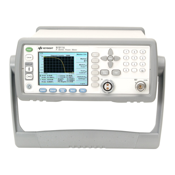


Need help?
Do you have a question about the N1911A and is the answer not in the manual?
Questions and answers