
Related Manuals for Mueller SENTRY II


Summary of Contents for Mueller SENTRY II
- Page 1 SENTRY II ® WITH AUTO-DOSING ASSEMBLY INSTALLATION AND OPERATION MANUAL PART NO. 8823644 EFFECTIVE 4/1/00 ® THE MILK COOLING SYSTEMS SPECIALISTS...
-
Page 3: Table Of Contents
Regulatory Requirements ............1 Figure 1 - Sentry II Control Cabinet and Milk Cooler Components ......2 Section 2.0 - Installation... - Page 4 Sentry II Temperature Control and Thermocouple Sensor ....... . .25...
- Page 5 Sentry II Service Reference Form, Programmable Features ....... . .51...
- Page 6 10.26 Label No. 8822558, Mueller Milk Cooler Data Tag ....... .
-
Page 7: Section 1.0 - Introduction Page
This manual provides the basic installation and operating information to ensure safe and optimum performance of the Sentry II control system. Please contact your local Mueller Sales and Service Representative if you require additional technical assistance pertaining to installation or operating procedures. -
Page 8: Figure 1 - Sentry Ii Control Cabinet And Milk Cooler Components
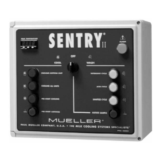
Figure 1 - Sentry II Control Cabinet and Milk Cooler Components A. Sentry II Control Box M. Peristaltic Pump Priming Switch B. Alarm Indicator N. Priming Selector Switch C. Detergent Switch/Indicator O. Peristaltic Pump (Sanitize) D. Acid Switch/Indicator Peristaltic Pump (Acid) E. -
Page 9: Section 2.0 - Installation
4. Raise one end of the milk cooler with a floor jack and wooden-cradle block. Pivot the skids away from the milk cooler. Lower the milk cooler and repeat the procedure for the other end. Figure 2 - Skid Removal Sentry II with Auto-Dosing Assembly Operating Instructions Effective April 1, 2000... -
Page 10: Site Requirements
Operation Manual specific to the refrigeration unit(s) being installed. NOTE: All wiring to be performed in accordance with the National Electrical Code and/or regulatory agency for the installation locality. All wiring that enters the Sentry II control box must be sealed with cord grips or liquid-tight conduit connectors. -
Page 11: Foundation Requirements
IMPORTANT NOTE: Mueller warrants to the original purchaser/user that the Mueller factory calibration of a Mueller milk cooler will not be affected (i.e. exceed the tolerances prescribed by the National Institute of Standards and Technology) by distortion or structural change for a period of five (5) years from the date of installation or sixty-six (66) months from the date of shipment from the Company factory, whichever occurs first. -
Page 12: Leveling The Milk Cooler
7. Ensure that the final location and position complies with all regulations for the installation locality, including the proper height of the milk outlet and the proper dimensions beneath and around the milk cooler. Figure 4 - Leveling the Milk Cooler Sentry II with Auto-Dosing Assembly Operating Instructions Effective April 1, 2000... -
Page 13: Bulk Head Installations
If the milk cooler is bulkheaded through a wall, the wall must be free-standing and not load bearing against the milk cooler. Mueller offers an optional steel-formed structural support channel that may be installed in masonry walls to prevent the wall from bearing load on the milk cooler. Contact Mueller’s Sales Department for availability and pricing. -
Page 14: Milk Room Installations
1.125" rubber grommets, which provides a method to support the water/chemical fill hose inside of .75" PVC conduit. See Figure 7. Figure 7 - Milk Room Installations Sentry II with Auto-Dosing Assembly Operating Instructions Effective April 1, 2000... -
Page 15: Agitator Assembly Installation
6. The optional agitator weather shield (Item 13) must be installed on all agitators that are located exterior of the milk room. Figure 8 - Agitator Installation Sentry II with Auto-Dosing Assembly Operating Instructions Effective April 1, 2000... -
Page 16: Pump Assembly And Electric Drain Installation
24-vac electric drain valve coil. 12. Reattach the stainless steel cover plate and tighten all cord grips and liquid-tight conduit fittings. Figure 9 - Pump Assembly and Electric Drain Installation Sentry II with Auto-Dosing Assembly Operating Instructions Effective April 1, 2000... -
Page 17: Instructions For Mounting The Sentry Ii Control Box Enclosures
2.13 Instructions for Mounting the Sentry II Control Box Enclosures 1. Install the Sentry II control box in a location where it is easily accessible for the operator and protected from excessive wash down. 2. Install the peristaltic pump box and manifold box in an area protected from freezing and within easy access to the chemical storage drums. -
Page 18: Chemical Line Connections
Always observe the chemical manufacturer’s precautions, warnings, and usage recommendations! Store all chemicals in a location protected from freezing, unauthorized access, and direct sunlight. CAUTION WEAR EYE PROTECTION, POISON CORROSIVE RUBBER GLOVES, AND APRONS WHEN HANDLING CHEMICALS Sentry II with Auto-Dosing Assembly Operating Instructions Effective April 1, 2000... -
Page 19: Manway Wash Tube Installation
Refer to the drawing in Figure 11 for detailed installation procedures. Figure 11 - Manway Wash Tube Sentry II with Auto-Dosing Assembly Operating Instructions Effective April 1, 2000... -
Page 20: Spray Dish Installation
Figure 12 - Spray Dish Orientation Figure 13 - Spray Dish Rectangular notch must face front and rear heads of the milk cooler. Orient slot towards the center of the agitator shaft. Sentry II with Auto-Dosing Assembly Operating Instructions Effective April 1, 2000... -
Page 21: Milk Cooler Vent Assembly Installation
Mueller Model “O,” “OE,” “OH,” and “OHF” milk coolers are designed for operation at normal atmospheric pressure only. -
Page 22: Section 3.0 - Electrical Wiring
Open the quick-connect terminal connection by inserting a 3-mm screwdriver into the bottom of socket “A”. Following the electrical schematics, insert the correct conductor into terminal connection “B” and remove the screwdriver, allowing the quick-connect terminal to close on the conductor. Sentry II with Auto-Dosing Assembly Operating Instructions Effective April 1, 2000... -
Page 23: Figure 16—Electrical Schematic - Wash Pump Motor
Figure 16 - Electrical Schematic - Wash Pump Motor Figure 17 - Electrical Schematic - Agitator Motor(s) Figure 18 - Electrical Schematic - Rear Junction Box Sentry II with Auto-Dosing Assembly Operating Instructions Effective April 1, 2000... -
Page 24: Figure 19—Internal Conduit Raceways - Milk Cooler
Figure 19 - Internal Conduit Raceways - Milk Cooler Sentry II with Auto-Dosing Assembly Operating Instructions Effective April 1, 2000... - Page 25 Figure 20 - Electrical Schematic - Field Wiring (Enlarged Schematic Attached in Back) Sentry II with Auto-Dosing Assembly Operating Instructions Effective April 1, 2000...
- Page 26 Figure 21 - Electrical Schematic - Factory Wiring (Enlarged Schematic Attached in Back) Sentry II with Auto-Dosing Assembly Operating Instructions Effective April 1, 2000...
-
Page 27: Figure 22—Sentry Ii Relay And Switch Contact Positions
Figure 22 - Sentry II Relay and Switch Contact Positions Sentry II with Auto-Dosing Assembly Operating Instructions Effective April 1, 2000... -
Page 28: Plc Electrical Troubleshooting (Input And Output Data)
Acid Chemical Pump Not Used Y15 (240VAC) Sanitize Chemical Pump Service Note: Inputs “X” are 24 VDC, outputs “Y0 - Y11” are 24 VAC, and “Y12 - Y15” are 240 VAC. Sentry II with Auto-Dosing Assembly Operating Instructions Effective April 1, 2000... -
Page 29: Figure 23—Electrical Schematic - Plc
Figure 23 - Electrical Schematic - PLC Sentry II with Auto-Dosing Assembly Operating Instructions Effective April 1, 2000... -
Page 30: Figure 24—Electrical Schematic - Peristaltic Pumps
Figure 24 - Electrical Schematic - Peristaltic Pumps Sentry II with Auto-Dosing Assembly Operating Instructions Effective April 1, 2000... -
Page 31: Section 4.0 - Sentry Ii Temperature Control
SECTION 4.0 - SENTRY II TEMPERATURE CONTROL Sentry II Temperature Control and Thermocouple Sensor The Sentry II control uses an electronic temperature control with digital display and a Type “T” thermocouple sensor. The following installation and calibration procedures are very important to ensure accurate sensing of the milk temperature. -
Page 32: Sentry Ii Thermocouple Sensor Wiring
Cut and insulate the foil shield and drain wire of the thermocouple extension cable at the top-rear junction box. The drain wire should be grounded (one end only) at the Sentry II control cabinet. Route the thermocouple extension cable from the rear junction box to the wall-mounted Sentry II. -
Page 33: Important Thermocouple Splicing Information
Use non-metallic wire nuts, Mueller Part No. 8822361, to make all spliced thermocouple connections. If thermocouple extension cable is required, Mueller Part No. 8820166, connect the drain wire to the electrical ground at the Sentry II enclosure and cap and insulate the foil shield and drain wire at the opposite end. -
Page 34: Sentry Ii Temperature Control Lock And Unlock Features
Sentry II Temperature Control Lock and Unlock Features The temperature control is equipped with a locking feature to prevent unauthorized adjustments to the calibration, temperature set points, and unit of measure. Unlock - To unlock the temperature control for adjustment, press and hold the keys (see Figure 28) simultaneously for two seconds. -
Page 35: Sentry Ii Temperature Control Calibration
Lock the temperature control by pressing and holding the keys simultaneously for 4 seconds. When released the display will blink once indicating a successful lock, otherwise repeat the process. Sentry II with Auto-Dosing Assembly Operating Instructions Effective April 1, 2000... -
Page 36: Sentry Ii Temperature Control Set Point Adjustment
The display will blink once when the keys are released, informing you that the control was successfully locked. See Section 4.6. Sentry II Temperature Control Unit of Measure (Fahrenheit or Celsius) 1. Unlock the temperature control as instructed in Section 4.6. -
Page 37: Section 5.0 - Automatic Chemical Dosing
Store chemicals in an area that prevents access by children or unauthorized individuals. CAUTION CAUTION WEAR EYE PROTECTION, CORROSIVE WEAR EYE PROTECTION, RUBBER GLOVES, AND RUBBER GLOVES, AND APRONS WHEN HANDLING APRONS WHEN HANDLING CHEMICALS CHEMICALS Sentry II with Auto-Dosing Assembly Operating Instructions Effective April 1, 2000... -
Page 38: Peristaltic Pump Priming
Safely dispose of the small amount of chemical in the glass jar. Thoroughly wash all chemical traces from the glass jar and repeat the procedure for the remaining peristaltic chemical pumps. Figure 29 - Peristaltic Pump Priming Sentry II with Auto-Dosing Assembly Operating Instructions Effective April 1, 2000... -
Page 39: Adjusting Peristaltic Pump Timers For Proper Chemical Concentration
Using the Chemical Supplier’s concentration recommendations, select the required run time in seconds for each of the cleaning chemicals from Tables 3A - 3C. Sentry II with Auto-Dosing Assembly Operating Instructions Effective April 1, 2000... -
Page 40: Table 3A—Peristaltic Pump Timing For Specific Chemical Concentrations (2-240 Seconds)
Table 3A - Peristaltic Pump Timing for Specific Chemical Concentrations (2 - 240 seconds) Sentry II with Auto-Dosing Assembly Operating Instructions Effective April 1, 2000... -
Page 41: Table 3B—Peristaltic Pump Timing For Specific Chemical Concentrations (240-478 Seconds)
Table 3B - Peristaltic Pump Timing for Specific Chemical Concentrations (240 - 478 seconds) Sentry II with Auto-Dosing Assembly Operating Instructions Effective April 1, 2000... -
Page 42: Table 3C—Peristaltic Pump Timing For Specific Chemical Concentrations (478-726 Seconds)
Table 3C - Peristaltic Pump Timing for Specific Chemical Concentrations (478 - 726 seconds) Sentry II with Auto-Dosing Assembly Operating Instructions Effective April 1, 2000... -
Page 43: Determining Water Usage Requirements
Determining Water Usage Requirements The PLC in the Sentry II is supplied with a potentiometer that allows the volume of fill water to be adjusted for each specific installation. As the timer is turned clockwise to increase the volume of wash water, it automatically increases the electric drain time to ensure adequate drainage at the end of each cycle. -
Page 44: Determining Actual Water Usage
204.41 54.00 13.00 155.50 41.08 184.54 48.75 211.60 55.90 221.45 58.50 14.00 167.47 44.24 198.73 52.50 227.88 60.20 238.48 63.00 15.00 179.43 47.40 212.93 56.25 244.16 64.50 255.52 67.50 Sentry II with Auto-Dosing Assembly Operating Instructions Effective April 1, 2000... -
Page 45: Wash Cycle Timing Sequence
Wash Cycle Timing Sequence The Sentry II provides several programming options for the wash cycles. See Section 6 for detailed information. Chart 1 - (Detergent Wash or Complete Wash) NOTE: Fill and drain times are charted with the PLC potentiometer turned to the far counterclockwise position. -
Page 46: Chart 2-Acid Cycle Or Sanitize Cycle
Chart 2 - (Acid Cycle or Sanitize Cycle) NOTE: Fill and drain times are charted with the PLC potentiometer turned to the far counterclockwise position. See Section 5.6 and Figure 31. Sentry II with Auto-Dosing Assembly Operating Instructions Effective April 1, 2000... -
Page 47: Section 6.0 - Sentry Ii Plc Programming
SECTION 6.0 - SENTRY II PLC PROGRAMMING Sentry II Programmable Features, Options, and Recommendations The Sentry II offers the following programming options, allowing the cooling and washing procedures to be customized for each specific installation: Programming Selectable Reference Feature Description and Recommendations... -
Page 48: Sentry Ii - Mta To Plc Programming Procedures
Sentry II - MTA to PLC Programming Procedures 1. Open the hinged door on the PLC. 2. Energize the power supply to the Sentry II Control before proceeding to Step 3. 3. Plug the MTA into the PLC. ▲ CAUTION: Be careful not to touch any terminals, power is applied! 4. - Page 49 PROGRAMMING NOTE: If ➞ RETURN TO MENU is displayed at any time, press the ✚ key to return to SENTRY II, and use the ▼ to scroll back to the desired programmable option. 7. Press the ▼ key to scroll to the first programmable selection, “Bottom...
- Page 50 ➞ Cond Side Units 13. Press the ✚ key to display the current time delay setting—0-120 minutes. The MTA will display the current time delay selection: xx Minute Delay Sentry II with Auto-Dosing Assembly Operating Instructions Effective April 1, 2000...
- Page 51 The MTA will display: SENTRY II 17. Press the ▼ key, scrolling past the previous programmable selection, to the next option, “Pre-Start Cooling.” The MTA will display: ➞ Pre-Start Cool Sentry II with Auto-Dosing Assembly Operating Instructions Effective April 1, 2000...
- Page 52 27. Press the ▼ key to scroll to the next option, "Agitation Interval Timer.” 28. Press the ✚ key to display the current settings—3 out of every 30 minutes or 3 out of every 18 minutes. Sentry II with Auto-Dosing Assembly Operating Instructions Effective April 1, 2000...
- Page 53 36. Press the ✚ key to enter the new setting. 37. Press the key to enter the selection. 38. Press the ✚ key to return to the main menu. Sentry II with Auto-Dosing Assembly Operating Instructions Effective April 1, 2000...
- Page 54 46. Press the ✚ key to turn the Fifth-Cycle On, or key to turn it Off. 47. Press the key to enter the selection. 48. Press the ✚ key to return to the main menu. Sentry II with Auto-Dosing Assembly Operating Instructions Effective April 1, 2000...
- Page 55 56. Press the ✚ key to select Warm or the to select Cold. 57. Press the key to enter the selection. 58. Press the ✚ key to return to the main menu. Sentry II with Auto-Dosing Assembly Operating Instructions Effective April 1, 2000...
- Page 56 68. Programming is complete, unplug the MTA from the PLC. Note: De-energize the power supply to the Sentry II for 5 minutes after making any programming changes. This will ensure that the changes are stored to the E.Prom of the PLC.
-
Page 57: Sentry Ii Service Reference Form, Programmable Features
Sentry II Service Reference Form, Programmable Features Please complete for future service reference: Mueller Authorized Dealer: End User/Owner: Name: Name: Address: Address: Phone: Phone: Contact: Contact: Please check the selected program options: Description: Options and Selection Bottom Unit(s) Cooling Delay... -
Page 58: Section 7.0 - Operating Instructions
The Sentry II control system is designed for easy, touch-of-a-button operation with simple visual notification of each operational mode with bright, illuminated indicators. Please locate the enclosed plastic laminated reference chart, Part No. 8823066, near the Sentry II control. This will provide unfamiliar operators with a quick reference to the basic operation and features of the Sentry II control system. -
Page 59: Cooling All Units Switch
2. This feature blends the warm incoming milk at the onset of the second, third, or fourth milkings. 3. To cancel “Pre-Start Agitation” press the switch a second time. Sentry II with Auto-Dosing Assembly Operating Instructions Effective April 1, 2000... -
Page 60: Detergent Cycle Switch
Flashing at second intervals—The milk temperature is below a safe holding temperature and near freezing. (Call a Mueller Authorized Service Technician.) c. Constant illumination—Wash water did not enter the milk cooler within 2 minutes of a fill cycle. (Call a Mueller Authorized Service Technician.) 2. -
Page 61: Milk Temperature Display
2. To access and activate this switch, turn the power off to the Sentry II control box, open the door and move this switch to the “Manual” position. Close the door, turn selector switch to the “Cool”... -
Page 62: Section 8.0 - Weights And Dimensions
Actual calibration capacity may exceed certified capacity Minimum and maximum clearance under the milk cooler with standard adjustable legs. Approximate weight measured in pounds (includes agitator(s), pump assembly, and controls). Sentry II with Auto-Dosing Assembly Operating Instructions Effective April 1, 2000 Revised February 5, 2001... -
Page 63: Metric Weights And Dimensions
Actual calibration capacity may exceed certified capacity Minimum and maximum clearance under the milk cooler with standard adjustable legs. Approximate weight measured in kilograms (includes agitator(s), pump assembly, and controls). Sentry II with Auto-Dosing Assembly Operating Instructions Effective April 1, 2000... -
Page 64: Section 9.0 - Sentry Ii Replacement Parts
SECTION 9.0 - SENTRY II REPLACEMENT PARTS Sentry II Replacement Parts Drawing, Main Control Sentry II with Auto-Dosing Assembly Operating Instructions Effective April 1, 2000... -
Page 65: Sentry Ii Replacement Parts List, Main Control
Sentry II Replacement Parts List, Main Control ITEM PART NO. DESCRIPTION 8822971 TRANSFORMER, 240/24 VAC, 75 VA (SEE ITEM 2 FOR 195 VAC) 8823060 TRANSFORMER, 195/24 VAC, 150 VA 8823007 RELAY, DPST, 240 VAC COIL, 30 AMP, NO 8822995 TEMPERATURE CONTROLLER, THERMOCOUPLE INPUT, 2 RELAY OUTPUT... -
Page 66: Sentry Ii Replacement Parts Kit, Dosing And Manifold Box
Sentry II Replacement Parts Kit, Dosing and Manifold Box Sentry II with Auto-Dosing Assembly Operating Instructions Effective April 1, 2000... -
Page 67: Sentry Ii Replacement Parts List, Dosing And Manifold Box
Sentry II Replacement Parts List, Dosing and Manifold Box ITEM PART NO. DESCRIPTION 8823002 BOX ASSEMBLY DOSING, SENTRY II (INCLUDES ITEMS 1-14), STANDARD LABEL 8823365 BOX ASSEMBLY DOSING, SENTRY II (INCLUDES ITEMS 1-14), JAPANESE LABEL 8822996 TIMER, 230 VAC, 1-1023 SECONDS, DIP SWITCH SELECTABLE... -
Page 68: Sentry Ii Replacement Parts Kit, Pump Assembly
Sentry II Replacement Parts Kit, Pump Assembly Sentry II with Auto-Dosing Assembly Operating Instructions Effective April 1, 2000... -
Page 69: Sentry Ii Replacement Parts List, Pump Assembly
Sentry II Replacement Parts List, Pump Assembly ITEM PART NO. DESCRIPTION 30455 MOTOR, ELECTRIC, .75 HP, 208-230/50-60/1 8823665 MOTOR, ELECTRIC, .75 HP, STAINLESS STEEL, 208-230/50-60/1 30456 MOTOR, ELECTRIC, 1.5 HP, 208-230/50-60/1 8823666 MOTOR, ELECTRIC, 1.5 HP, STAINLESS STEEL, 208-230/50-60/1 3909... -
Page 70: Section 10.0 - Sentry Ii Equipment Markings
SECTION 10.0 - SENTRY II EQUIPMENT MARKINGS 10.1 Label No. 8822229, Lock Out LOCK OUT HERE 10.2 Label No. 8820482, Caution - Disconnect Power and Retain Latch ▲ CAUTION BEFORE ENTERING TANK DISCONNECT POWER TO AGITATOR. REMOVE AND RETAIN COVER LATCH. -
Page 71: Label No. 8820248, Auto - Automatic Run Position
Label No. 8822584, Pump Motor - Wire Marker PUMP MOTOR 8822584 10.10 Label No. 8802375, Agitator(s) - Wire Marker AGITATOR(S) 8802375 10.11 Label No. 3791, Hot - Water Valve Marker 3791 Sentry II with Auto-Dosing Assembly Operating Instructions Effective April 1, 2000... -
Page 72: Label No. 8823609, Warning - Manifold Box
▲ ADVERTISSEMENT Separez l’unité réfrigérant et la cabine de contrôle du systéme Mueller Matic ® du câble de distribution avant de réparer. 8801150 Sentry II with Auto-Dosing Assembly Operating Instructions Effective April 1, 2000... -
Page 73: Label No. 8822225, Ce Data Tag (U.k. Models Only)
10.15 Part No. 8822225, CE Data Tag (U.K. Models Only) ® Paul Mueller Company • 1600 W. Phelps • P.O. Box 828 • Springfield, Missouri 65801-0828, U.S.A. Year of Construction Model Number Serial Number Noise Level Weight 6911 8822225 10.16 Label No. -
Page 74: Label No. 8820454, Dry Nitrogen Holding Charge
SOBRE LAS SUBSTANCIAS EMPOBRECEDORAS DE LA CAPA DE OZONO - LEY PARA LA CONSERVACION DEL AMBIENTE LIMPIO. N.B. La presente norma se ha consolidado hasta el 30 de septiembre de 1992. 8805299 10.20 Label No. 30737, Bottom Temp-Plate BOTTOM TEMP-PLATE ® 30737 Sentry II with Auto-Dosing Assembly Operating Instructions Effective April 1, 2000... -
Page 75: Label No. 8822972, Transformer Wiring
(240 VAC) 17 Pump Motor (240 VAC) 18 Agitator Motor (240 VAC) 19 Agitator Motor (240 VAC) L1 Main Power (240 VAC) L2 Main Power (240 VAC) 0003 8822948 Sentry II with Auto-Dosing Assembly Operating Instructions Effective April 1, 2000... -
Page 76: Label No. 8820409, Mueller Name Tag
Label No. 8820409, Mueller Name Tag 8820409 10.25 Label No. 8822980, Programmable Controller Name Tag PLC Part No. 8823313 (9907) 8822980 10.26 Label No. 8822558, Mueller Milk Cooler Data Tag Sentry II with Auto-Dosing Assembly Operating Instructions Effective April 1, 2000... -
Page 77: Label No. 30890, Mueller Data Tag - Control Box
10.27 Label No. 30890, Mueller Data Tag - Control Box ® PRODUCT MODEL NUMBER PART NUMBER SERIAL NUMBER VOLTS HERTZ PHASE DISCONNECT MAIN POWER SUPPLY BEFORE SERVICING. 6911 ROMPRE LE CABLE DE DISTRIBUTION AVANT DE REPARER 30890 10.28 Label No. 8820677, Ground Symbol 10.29... -
Page 78: Label No. 30166, Caution - Vent Must Be Over Milk Inlet
Do not exceed 170°F(76°C) during the wash cycles. 8905 8802777 Sentry II with Auto-Dosing Assembly Operating Instructions Effective April 1, 2000... -
Page 79: Label No. 8823146, Terminal Block - 24 Vac - 240 Vac
(240v AC) L2 Main Power (240v AC) 20 Used for Internal Wiring (240v AC) 21 Used for Internal Wiring (240v AC) 22 Used for Internal Wiring (240v AC) 9904 8823263 Sentry II with Auto-Dosing Assembly Operating Instructions Effective April 1, 2000... -
Page 80: Section 11.0 - Safety
Note: See all safety, warning, and caution labels displayed in Section 10. 11.1 General The Mueller milk cooler and Sentry II control system should be operated by qualified personal who are familiar with the equipment and instructions. Improper handling, operation, or service of the equipment, cleaning chemicals, and/or electricity can create a health hazard and possible non-warranted damage to the equipment. -
Page 81: Section 12.0 - Disposal
The milk cooler’s basic components consist of steel, copper, rubber, and plastics which may be separated and recycled. The “CFC-Free” foam insulation should be disposed of according to local environmental regulations and agencies. Sentry II with Auto-Dosing Assembly Operating Instructions Effective April 1, 2000... - Page 82 Sentry II Service Reference Form, Programmable Features Please detach, complete, and leave in Sentry II control box for future reference. Mueller Authorized Dealer: End User/Owner: Name: Name: Address: Address: Phone: Phone: Contact: Contact: Please check the selected program options: Description:...
- Page 83 ® P.O. Box 828 • Springfield, Missouri 65801-0828, U.S.A. Phone: (417) 831-3000 • 1-800-MUELLER • Fax: 1-800-436-2466 www.muel.com • E-mail: dairyfarm@muel.com International Inquiries - Fax: (417) 831-6906 • E-mail: international@muel.com (2/00) 8823644...
Need help?
Do you have a question about the SENTRY II and is the answer not in the manual?
Questions and answers