FLIR E95 User Manual
Flir exx series
Hide thumbs
Also See for FLIR E95:
- Operation instructions manual (426 pages) ,
- User manual (328 pages) ,
- User manual (300 pages)
Table of Contents
Advertisement
Quick Links
Advertisement
Table of Contents

Related Manuals for FLIR FLIR E95


Summary of Contents for FLIR FLIR E95
- Page 1 User’s manual FLIR Exx series...
- Page 3 User’s manual FLIR Exx series #T810190; r. AI/41890/41890; en-US...
-
Page 5: Table Of Contents
Table of contents Disclaimers ..................1 Legal disclaimer ................. 1 Usage statistics ................1 Changes to registry ..............1 U.S. Government Regulations............1 Copyright .................. 1 Quality assurance ............... 1 Patents ..................1 EULA Terms ................1 EULA Terms ................2 Safety information ................3 Notice to user ..................7 User-to-user forums .............. - Page 6 Table of contents Navigating the menu system ............... 25 General .................. 25 Navigating using the navigation pad ..........25 Handling the camera................26 10.1 Charging the battery ..............26 10.1.1 General................ 26 10.1.2 Using the USB battery charger to charge the battery ....26 10.1.3 Using the stand-alone battery charger to charge the battery .................
- Page 7 Table of contents 10.16.1 General................ 43 10.16.2 Mounting the wrist strap........... 44 10.17 Front protection ................ 45 10.18 Changing camera lenses ............46 10.19 Calibrating the compass ............. 48 10.19.1 Procedure ..............48 Saving and working with images ............50 11.1 About image files ..............
- Page 8 Table of contents Achieving a good image ..............59 13.1 General .................. 59 13.2 Adjusting the infrared camera focus ..........59 13.2.1 Manual focus ..............59 13.2.2 Autofocus ..............59 13.2.3 Continuous autofocus ............. 59 13.3 Adjusting the infrared image ............60 13.3.1 General................
- Page 9 22.2 Setting up a wireless access point (most common use) ..... 95 22.3 Connecting the camera to a WLAN (less common use) ..... 95 Fetching data from external FLIR meters ..........96 23.1 General .................. 96 23.2 Technical support for external meters ..........96 23.3...
- Page 10 26.18 FLIR E95 42° + 14° ..............190 26.19 FLIR E95 24° + 14° ..............196 26.20 FLIR E95 24° + 42° ..............202 26.21 FLIR E95 24° + 14° & 42° ............208 Mechanical drawings ............... 214 CE Declaration of conformity ............216 Application examples...............
- Page 11 33.1 Introduction ................233 33.2 Definition—what is calibration? ..........233 33.3 Camera calibration at FLIR Systems ........... 233 33.4 The differences between a calibration performed by a user and that performed directly at FLIR Systems........234 33.5 Calibration, verification and adjustment........234 33.6...
-
Page 13: Disclaimers
FLIR Systems will, at its option, repair or replace any such defective product free of charge if, upon inspection, it proves to be defective in material or work- 1.8 EULA Terms manship and provided that it is returned to FLIR Systems within the said one- year period. •... -
Page 14: Eula Terms
WITHOUT ANY WARRANTY; without even the implied warranty of MERCHANTABILITY or FITNESS FOR A PARTICULAR PURPOSE. See the Qt4 Core and Qt4 GUI, Copyright ©2013 Nokia Corporation and FLIR Sys- GNU Lesser General Public License, http://www.gnu.org/licenses/lgpl-2.1.html. tems AB. This Qt library is a free software; you can redistribute it and/or modify... -
Page 15: Safety Information
WARNING Applicability: Digital devices subject to 15.21. NOTICE: Changes or modifications made to this equipment not expressly approved by FLIR Systems may void the FCC authorization to operate this equipment. WARNING Applicability: Digital devices subject to 2.1091/2.1093/OET Bulletin 65. - Page 16 Applicability: Cameras with one or more batteries. Do not attach the batteries directly to a car’s cigarette lighter socket, unless FLIR Systems supplies a spe- cific adapter to connect the batteries to a cigarette lighter socket. Damage to the batteries can occur.
- Page 17 Safety information CAUTION Applicability: Cameras with one or more batteries. Do not get water or salt water on the battery, or permit the battery to become wet. Damage to the batteries can occur. CAUTION Applicability: Cameras with one or more batteries. Do not make holes in the battery with objects.
- Page 18 CAUTION Only use the camera with a battery that has the item part number T199424 on it (that FLIR Systems sup- plies). If you do not obey this, damage to the equipment can occur and the protection that the equipment gives can become unsatisfactory.
-
Page 19: Notice To User
As with most electronic products, this equipment must be disposed of in an environmen- tally friendly way, and in accordance with existing regulations for electronic waste. Please contact your FLIR Systems representative for more details. 3.5 Training To read about infrared training, visit: •... -
Page 20: Important Note About This Manual
Notice to user 3.7 Important note about this manual FLIR Systems issues generic manuals that cover several cameras within a model line. This means that this manual may contain descriptions and explanations that do not apply to your particular camera model. -
Page 21: Customer Help
Customer help 4.1 General For customer help, visit: http://support.flir.com 4.2 Submitting a question To submit a question to the customer help team, you must be a registered user. It only takes a few minutes to register online. If you only want to search the knowledgebase for existing questions and answers, you do not need to be a registered user. -
Page 22: Downloads
• The communication protocol, or method, between the camera and your device (for ex- ample, SD card reader, HDMI, Ethernet, USB, or FireWire) • Device type (PC/Mac/iPhone/iPad/Android device, etc.) • Version of any programs from FLIR Systems • Full name, publication number, and revision number of the manual 4.3 Downloads... -
Page 23: Quick Start Guide
10. Start FLIR Tools/Tools+ or FLIR Report Studio. 11. Connect the camera to the computer using the USB cable. 12. Import the images into FLIR Tools/Tools+ or FLIR Report Studio and create an inspec- tion report. 13. Send the inspection report to your client. -
Page 24: Register The Camera
Register your camera to receive an extended warranty and other related benefits. To register the camera, you must log in using a FLIR Customer Support account. If you al- ready have an existing FLIR Customer Support account, you can use the same login cre- dentials. - Page 25 Register the camera 3. To create a new FLIR Customer Support account, do the following: 3.1. Click Create a New Account. 3.2. Enter the required information and click Create Account. 4. On the camera, select (Settings) Device settings > Camera information > Register camera.
- Page 26 Register the camera 5. Select Register and push the navigation pad. This displays a dialog box with the serial number of the camera. 6. On the computer, enter the serial number of the camera and click Validate. 7. When the serial number is validated, click Continue. #T810190;...
- Page 27 9. When the registration is completed, the four-digit code is displayed. Note • The code is also sent by e-mail to the address registered with your FLIR Customer Support account. • The code is also displayed in your FLIR Customer Support portal under My Stuff >...
- Page 28 Register the camera 10. On the camera, do the following to enter the code: • Push the navigation pad up/down to select a digit. • Push the navigation pad left/right to navigate to the previous/next digit. • When all digits have been entered, push the navigation pad right to select Submit. Push the navigation pad to confirm.
-
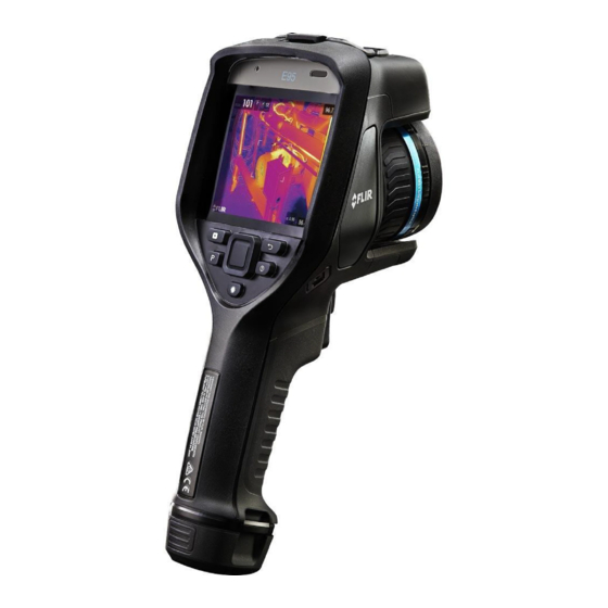
Page 29: Camera Parts
Camera parts 7.1 View from the front 7.1.1 Figure 7.1.2 Explanation 1. Laser distance meter. 2. Infrared lens. 3. Focus ring. 4. Autofocus button. 5. Trigger. 6. Lamp for the digital camera (left and right sides). 7. Digital camera. 8. Attachment point for the hand strap bracket (left and right sides). 9. -
Page 30: View From The Rear
Camera parts 10. Attachment point for the hand strap, wrist strap, or lanyard strap (left and right sides). 7.2 View from the rear 7.2.1 Figure 7.2.2 Explanation 1. Cover for the USB connector and memory card slot. 2. Microphone. 3. Speaker. 4. -
Page 31: Laser Distance Meter And Laser Pointer
Camera parts 7. Button to operate the laser. 8. Back button. 9. On/off button. 10. Navigation pad with center push. 11. Battery. 7.3 Laser distance meter and laser pointer 7.3.1 General The laser distance meter consists of a laser transmitter and a laser receiver. The laser dis- tance meter determines the distance to a target by measuring the time it takes for a laser pulse to reach the target and return to the laser receiver. -
Page 32: Laser Transmitter And Receiver
Camera parts 7.3.2 Laser transmitter and receiver 1. Laser transmitter. 2. Laser receiver. 7.3.3 Difference in position This figure shows the difference in position between the laser transmitter and the optical center of the infrared lens. #T810190; r. AI/41890/41890; en-US... -
Page 33: Laser Warning Label
Camera parts 7.3.4 Laser warning label A laser warning label with the following information is attached to the camera: 7.3.5 Laser rules and regulations Wavelength: 650 nm. Maximum output power: 1 mW. This product complies with 21 CFR 1040.10 and 1040.11 except for deviations pursuant to Laser Notice No. -
Page 34: Screen Elements
Screen elements 8.1 Figure 8.2 Explanation 1. Result table. 2. Status icons. 3. Measurement tool (e.g., spotmeter). 4. Temperature scale. 5. Submenu. 6. Main menu. 7. Settings button. 8. Color button. 9. Measurement button. 10. Image mode button. 11. Measurement parameters button. 12. -
Page 35: Swipe-Down Menu
Screen elements The GPS indicator. • Gray icon: GPS is enabled, but there is no sat- ellite contact. • White icon: GPS is enabled, with satellite contact. External infrared window compensation is enabled. Compass indicator (part of the image overlay information). - Page 36 Screen elements image archive. You can also choose to display selected items as image overlay informa- tion. All image overlay information displayed on the live image will also be displayed on saved images. For more information, see sections section 24.1.5 Device settings, page 100 and 13.8 Hiding all overlay, page 65.
-
Page 37: Navigating The Menu System
Navigating the menu system 9.1 General The figure above shows the two ways to navigate the menu system in the camera: • Using your index finger or a stylus pen specially designed for capacitive touch usage to navigate the menu system (left). •... -
Page 38: Handling The Camera
Handling the camera 10.1 Charging the battery 10.1.1 General Note • Charge the battery for 2 hours before starting the camera for the first time. • Select a mains socket that is near the equipment and easily accessible. 10.1.2 Using the USB battery charger to charge the battery 10.1.2.1 Procedure Follow this procedure: 1. -
Page 39: Using The Stand-Alone Battery Charger To Charge The Battery
Handling the camera 5. To check the status of the battery charging, do one of the following: • If the camera is turned on: Place your finger at the top of the screen and swipe down. The battery status is displayed on the swipe-down menu. •... -
Page 40: Removing The Battery
Handling the camera 2. Connect a USB cable to the USB-C connector in the connector bay. Connect the other end of the USB cable to the computer. Note • To charge the camera, the computer must be turned on. • Charging the camera using a USB cable connected to a computer takes considerably longer than using the USB battery charger or the stand-alone battery charger. -
Page 41: Turning On And Turning Off The Camera
Handling the camera 10.3 Turning on and turning off the camera • To turn on the camera, push the on/off button • To turn off the camera, push and hold the on/off button for more than 0.5 second. Note Do not remove the battery to turn off the camera. 10.4 Adjusting the infrared camera focus manually 10.4.1 Figure... -
Page 42: Autofocusing The Infrared Camera
Handling the camera Note It is very important to adjust the focus correctly. Incorrect focus adjustment affects how the image modes Thermal MSX, Thermal, and Picture-in-picture work. It also affects the temperature measurement. 10.5 Autofocusing the infrared camera 10.5.1 General When autofocusing, the infrared camera can use one of the following focus methods: •... -
Page 43: Continuous Autofocus
Handling the camera Note You can also assign the autofocus function to the programmable button . For more information, see section 10.12 Assigning functions to the programmable button, page 37. 10.6 Continuous autofocus 10.6.1 General The infrared camera can be set up to perform continuous autofocusing. When the continuous autofocus function is enabled, the camera bases the focus adjust- ments on continuous laser distance measurements. -
Page 44: Saving An Image
Handling the camera 10.7 Saving an image Follow this procedure: 1. To save an image, pull the trigger. Note Depending on the settings in (Settings) > Save options & storage, the following may happen: • A preview image is displayed before the image is saved. •... -
Page 45: Figure
Handling the camera Note • The laser is enabled by a setting. Select (Settings) > Device settings > Lamp & la- ser > Enable lamp & laser. • The symbol is displayed on the screen when the laser is on. •... -
Page 46: Measuring Areas
Handling the camera 10.9 Measuring areas 10.9.1 General The distance measured by the laser distance meter can be used as the basis for area cal- culations. A typical application is to estimate the size of a damp stain on a wall. To measure the area of a surface, you need to lay out a box or circle measurement tool on the screen. -
Page 47: Figure
Handling the camera 10.10.2 Figure 10.10.3 Explanation 1. LED indicator showing that the memory card is busy. Note • Do not eject the memory card when this LED is flashing. • Do not connect the camera to a computer when this LED is flashing. 2. -
Page 48: Procedure
• Move the files to the computer using a drag-and-drop operation in Microsoft Win- dows Explorer. Note Moving a file using a drag-and-drop operation does not delete the file in the camera. • Import the images into FLIR Tools/Tools+ or FLIR Report Studio. #T810190; r. AI/41890/41890; en-US... -
Page 49: Assigning Functions To The Programmable Button
Handling the camera 10.12 Assigning functions to the programmable button 10.12.1 General You can assign different functions to the programmable button . You can, for example, use the programmable button to easily switch between two settings you use often. You can also choose to define two different setups for saving and previewing: the ordinary set- up for the trigger (which is defined by the Save options and storage settings, see section 24.1.4 Save options &... -
Page 50: Procedure
Handling the camera • Preview + Prompt for voice annotation: Display a preview image and the voice annota- tion tool. • Preview + Prompt for sketch: Display a preview image and the sketch annotation tool. • Preview + Select annotation from menu: Display a preview image and the annotation tool menu. - Page 51 Handling the camera #T810190; r. AI/41890/41890; en-US...
-
Page 52: Mounting The Hand Strap
Handling the camera 10.14.2 Mounting the hand strap Follow this procedure: 1. Fit the upper part of the hand strap into the bracket. 2. Fit the bracket in place on the camera and tighten the screw with the supplied Torx key. #T810190;... - Page 53 Handling the camera 3. Thread the loose strap through the attachment point at the base of the camera. Secure the strap with the hook-and-loop fastener. #T810190; r. AI/41890/41890; en-US...
-
Page 54: Lanyard Strap
Handling the camera 10.15 Lanyard strap 10.15.1 General #T810190; r. AI/41890/41890; en-US... -
Page 55: Mounting The Lanyard Strap
Follow this procedure: 1. Remove the camera battery. 2. Starting with the FLIR logo part, thread the lanyard strap through the attachment point at the base of the camera. 3. Pull the entire lanyard strap through the attachment point until it stops. -
Page 56: Mounting The Wrist Strap
Follow this procedure: 1. Remove the camera battery. 2. Fold the wrist strap. Make sure that the part with the FLIR logo faces away from the bend. 3. Thread the bent wrist strap through the attachment point at the base of the camera. -
Page 57: Front Protection
Handling the camera 4. Pull the entire wrist strap through the attachment point until it stops. 10.17 Front protection To protect the camera lens and the laser distance meter, you can attach the front protec- tion by using the supplied fastening device. #T810190;... -
Page 58: Changing Camera Lenses
Handling the camera 10.18 Changing camera lenses Note Do not touch the lens surface when you change lenses. If this happens, clean the lens according to the instructions in 25.2 Infrared lens, page 103. Follow this procedure: 1. Take a firm grip around the blue ring of the lens. Rotate the blue ring 30° counter-clock- wise until it stops. - Page 59 Handling the camera 4. Make sure that the blue ring of the camera lens is fully in its open position. • Correct: The blue tooth (1) is in its end position at the black stop pin (2). • Wrong: You must rotate the blue ring until the blue tooth (1) reaches the black stop pin (2).
-
Page 60: Calibrating The Compass
Handling the camera 6. Rotate the blue ring of the lens 30° clockwise. The lens makes a click when it locks in place. 7. Make sure that the two index marks are aligned, indicating that the lens is locked in place. - Page 61 Handling the camera 5. Select Calibrate compass and push the navigation pad. Follow the on-screen instructions. Note You must rotate the camera slowly. #T810190; r. AI/41890/41890; en-US...
-
Page 62: Saving And Working With Images
The image *.jpg file is fully radiometric and saved lossless, which enables full post-proc- essing in image analysis and reporting software from FLIR Systems. There is also a regu- lar *.jpg component (lossy) for convenient viewing in non-FLIR Systems software (e.g., Microsoft Explorer). -
Page 63: Procedure
Saving and working with images 11.2.2 Procedure Follow this procedure: 1. To save an image, pull the trigger. Note Depending on the settings in (Settings) > Save options & storage, the following may happen: • A preview image is displayed before the image is saved. •... -
Page 64: Opening A Saved Image
Saving and working with images 3. To edit the image, push the navigation pad. This displays a context menu. For editing instructions, see section 11.5 Editing a saved image, page 52. 4. Do one of the following: • To save the image, pull the trigger. •... -
Page 65: Related Topics
Saving and working with images 7. Manual image adjustment mode is now active, and the status icon is displayed. For image adjustment instructions, see section 13.3 Adjusting the infrared image, page 8. Push the navigation pad. This displays a context menu. •... -
Page 66: Procedure
Saving and working with images 11.6.2 Procedure Follow this procedure: 1. To digitally zoom an image, do the following: • Zoom in: Touch the screen with two fingers and spread the fingers apart. • Zoom out: Touch the screen with two fingers and pinch the fingers together. 11.7 Deleting images You can delete image files from the memory card. -
Page 67: Working With The Image Archive
Working with the image archive 12.1 General When you save an image or video clip, the camera stores the image/video file in the image archive on the memory card. You can open an image in the image archive and, for exam- ple, select another image mode, apply color alarms, and add measurement tools. -
Page 68: Renaming A Folder
Working with the image archive 5. The new folder automatically becomes the active folder and appears at the top of the Gallery. 12.4 Renaming a folder Follow this procedure: 1. Push the image archive button . This displays the Gallery . 2. -
Page 69: Deleting A Folder
Working with the image archive 4. Use the navigation pad to select the image and video items you want to move. You can also select the items by touching the screen. Selected items are marked with a tick. 5. On the right toolbar, select the icon and push the navigation pad. -
Page 70: Deleting Multiple Files
Working with the image archive 12.9 Deleting multiple files 12.9.1 General You can delete multiple image and video files from the image archive. 12.9.2 Procedure Follow this procedure: 1. Push the image archive button . This displays the Gallery . 2. -
Page 71: Achieving A Good Image
Achieving a good image 13.1 General A good image depends on several different functions and settings, although some func- tions and settings affect the image more than others. These are the functions and settings that you need to experiment with: •... -
Page 72: Adjusting The Infrared Image
Achieving a good image 13.3 Adjusting the infrared image 13.3.1 General An infrared image can be adjusted automatically or manually. In automatic mode, the camera continuously adjusts the level and span for the best image presentation. The colors are distributed based on the thermal content of the image (histo- gram color distribution). -
Page 73: Example 2
Achieving a good image Automatic Manual 13.3.3 Example 2 Here are two infrared images of an isolator in a power line. To make it easier to analyze the temperature variations in the isolator, the temperature scale in the right image has been changed to values close to the temperature of the isolator. -
Page 74: Changing The Camera Temperature Range
Achieving a good image 2. Select (Temperature scale) and push the navigation pad. This displays a submenu. 3. Select (Manual) and push the navigation pad. 4. To simultaneously change the temperature scale minimum and maximum limits, push the navigation pad up/down. 5. -
Page 75: Changing The Color Palettes
Achieving a good image 13.5 Changing the color palettes 13.5.1 General You can change the color palette that the camera uses to display different temperatures. A different palette can make it easier to analyze an image. Iron Arctic Rainbow Rainbow high contrast #T810190;... -
Page 76: Procedure
Achieving a good image White hot Black hot Lava 13.5.2 Procedure Follow this procedure: 1. Push the navigation pad to display the menu system. 2. Select (Color) and push the navigation pad. This displays a submenu. 3. Use the navigation pad to select a different palette. 4. -
Page 77: Performing A Non-Uniformity Correction (Nuc)
Achieving a good image 13.7 Performing a non-uniformity correction (NUC) When the thermal camera displays Calibrating... it is performing what in thermography is called a ”non-uniformity correction” (NUC). An NUC is an image correction carried out by the camera software to compensate for different sensitivities of detector elements and oth- er optical and geometrical disturbances . -
Page 78: Procedure
Achieving a good image Image with all overlay hidden. Image with camera overlay and image overlay information. 13.8.2 Procedure Follow this procedure: 1. Push and hold the programmable button . This displays the Programmable button menu. 2. Push the navigation pad up/down to select the function Hide image overlay graphics . 3. -
Page 79: Working With Image Modes
• For the Thermal MSX, Thermal, and Picture in picture image modes, all thermal and visual information is stored when an image is saved. This means that you can edit the image later, in the image archive, or in FLIR Tools/Tools+ or FLIR Report Studio, and select any of the image modes. -
Page 80: Selecting An Image Mode
Working with image modes Image mode Image Picture in picture Digital camera 14.3 Selecting an image mode Follow this procedure: 1. Push the navigation pad to display the menu system. 2. Select (Image mode) and push the navigation pad. This displays a submenu. 3. -
Page 81: Working With Measurement Tools
Working with measurement tools 15.1 General To measure a temperature, you can use one or more measurement tools, e.g., a spotmeter or a box. 15.2 Adding/removing measurement tools Follow this procedure: 1. Push the navigation pad to display the menu system. 2. -
Page 82: Procedure
Working with measurement tools 15.3.2 Procedure Follow this procedure: 1. Push the navigation pad to display the menu system. 2. Select (Measurement) and push the navigation pad. This displays a submenu. 3. Use the navigation pad to select (User preset 1) or (User preset 2). -
Page 83: Moving And Resizing A Box Or Circle Tool
Working with measurement tools 3. To move the spot, do the following: 3.1. Select (Move spot) and push the navigation pad. 3.2. Push the navigation pad up/down and left/right to move the spot. 4. To center the spot, select Center spot and push the navigation pad. 5. -
Page 84: Recommended Values
Working with measurement tools Note The camera can be configured to automatically measure the distance when an image is saved. With this setting, the Object distance parameter in the image data is automatically updated with the measured distance when an image is saved. (There is no effect on the Object distance setting in live mode.) For more information, see section , page . - Page 85 Working with measurement tools 3. Use the navigation pad to select one or more of the global measurement parameters: • (External IR window compensation). • (Object distance). • (Atmospheric temperature). • (Relative humidity). • (Reflected temperature). • (Emissivity). 4. Push the navigation pad to display a dialog box. 5.
-
Page 86: Related Topics
Working with measurement tools 10. When completed, push the navigation pad and select (Done). 11. Push the navigation pad to confirm and exit the menu mode. Note When you select another measurement tool, the local parameters are reset. If you wish to keep the local parameter settings, use the user preset feature, see section 15.3 Editing user presets, page 69. -
Page 87: Creating And Setting Up A Difference Calculation
Working with measurement tools 5. Use the navigation pad to select one or more of the following: • Select (Max) to display the maximum value. • Select (Min) to display the minimum value. • Select (Avg) to display the average value. •... -
Page 88: Setting A Measurement Alarm
Working with measurement tools 3. Push the navigation pad. The result of the difference calculation is now displayed on the screen. 15.8 Setting a measurement alarm 15.8.1 General You can make the camera trigger an alarm when certain measurement conditions are met. 15.8.2 Types of alarm You can choose between the following alarm types: •... - Page 89 Working with measurement tools 15.8.4.2 Setting up an alarm for a box or circle Note This procedure assumes that you have previously set the camera to display at least one value (maximum, minimum, or average) in the result table. For more information, see section 15.6 Displaying values in the result table, page 74.
- Page 90 Working with measurement tools 5. In the dialog box, you can define the settings for the alarm. • Alarm condition: The condition that triggers the alarm. Applicable values are Above, Below, or Off. • Alarm limit: The temperature value that will be the critical condition when an alarm is triggered or not.
-
Page 91: Working With Color Alarms And Isotherms
Working with color alarms and isotherms 16.1 Color alarms 16.1.1 General By using color alarms (isotherms), anomalies can easily be discovered in an infrared im- age. The isotherm command applies a contrasting color to all pixels with a temperature above, below, or between the set temperature levels. The camera also features isotherm types that are specific to the building trade: condensation and insulation alarms. -
Page 92: Setting Up Above, Below, And Interval Alarms
Working with color alarms and isotherms Image Color alarm Interval alarm Condensation alarm Insulation alarm 16.1.3 Setting up above, below, and interval alarms Follow this procedure: 1. Push the navigation pad to display the menu system. 2. Select (Color) and push the navigation pad. This displays a submenu. 3. -
Page 93: Building Isotherms
Working with color alarms and isotherms 5. To change the threshold temperature, do the following: • For the Interval alarm, push the navigation pad left/right to select the low/high-tem- perature value. • Push the navigation pad up/down to change the threshold temperature. 16.1.4 Building isotherms Note The Condensation and Insulation alarms are not supported by all camera models. - Page 94 Working with color alarms and isotherms 4. Push the navigation pad. This displays a dialog box where you can define the settings for the alarm. For the Condensation alarm, the following parameters can be set: • Atmospheric temperature: The current atmospheric temperature. •...
-
Page 95: Annotating Images
Annotating images 17.1 General You can save additional information with an infrared image by using annotations. Annota- tions make reporting and post-processing more efficient by providing essential information about the image, e.g., conditions and information about where an image is taken. Annotations are added to the image file, and can be viewed and edited in the image ar- chive, and also when moving files from the camera to reporting software on the computer. -
Page 96: Adding A Text Comment Table
Annotating images 17.3 Adding a text comment table 17.3.1 General You can save a table with textual information to the image file. This feature is a very effi- cient way of recording information when you are inspecting a large number of similar ob- jects. -
Page 97: Creating A Text Comment Table Template
5. Save the template. 6. Do one of the following: • To use the template in the camera, connect a camera to FLIR Tools/Tools+ and transfer the template to the camera. • To use the template during post-analysis in FLIR Tools/Tools+, double-click an im- age, and then click Import from template under Text annotations in the right pane. - Page 98 17.3.3.3 Manually creating a table template 17.3.3.3.1 General A text comment file (*.tcf) is an annotation format that is proprietary to FLIR Systems. It de- fines a table structure that can be used to add text table annotations to FLIR images. You can create text comment files (*.tcf files) and use these files as table templates in the...
-
Page 99: Adding A Voice Annotation
A voice annotation is an audio recording that is saved to the infrared image file. The re- cording can be played back in the camera, and in image analysis and reporting software from FLIR Systems. The voice annotation is recorded using the built-in microphone. You can also use a Blue- tooth-enabled headset. -
Page 100: Adding A Sketch
Annotating images 17.5 Adding a sketch 17.5.1 General You can add a freehand drawing to an image. 17.5.2 Procedure Follow this procedure: 1. Open the image in the image archive. 2. Push the navigation pad to display the top toolbar. 3. -
Page 101: Programming The Camera (Time-Lapse)
Programming the camera (time- lapse) 18.1 General You can program the camera to save images periodically (time-lapse). 18.2 Procedure Follow this procedure: 1. Push the navigation pad to display the menu system. 2. Select (Settings) and push the navigation pad. This displays the Settings menu. 3. -
Page 102: Recording Video Clips
• Radiometric storage (*csq): A *.csq file supports full radiometry but is only supported by FLIR Systems software. The file does not include any visual image information. With this setting, only Thermal image mode is supported when recording video. If any other image mode is active when Video recording mode is selected, the camera will auto- switch to Thermal image mode. - Page 103 Recording video clips 4. Push the navigation pad to display the top toolbar. 5. On the top toolbar, select the icon and push the navigation pad. 6. To play or pause the video clip, push the navigation pad. #T810190; r. AI/41890/41890; en-US...
-
Page 104: Screening Alarm
Screening alarm 20.1 General The screening alarm can be used, for example, at airports to detect passengers with ele- vated body temperatures, which may indicate the presence of a fever. The screening alarm can also be used to detect temperature anomalies in a series of in- spected objects in a similar/fixed setup. - Page 105 Screening alarm Note • The algorithm has a memory of the last 10 samples. It discriminates between the high- est and lowest values, and calculates an average of the remaining values. • Do not modify the measurement setup or activate another alarm because this will deac- tivate the screening alarm.
-
Page 106: Pairing Bluetooth Devices
• You can remove a device by selecting the device and then selecting Unpair device. • After adding a METERLiNK device, such as the FLIR MR77 or FLIR DM93, the result from the meter will be visible in the result table and stored with the images. For more in- formation, see section 23 Fetching data from external FLIR meters, page 96. -
Page 107: Configuring Wi-Fi
Configuring Wi-Fi 22.1 General Depending on your camera configuration, you can connect the camera to a wireless local area network (WLAN) using Wi-Fi, or let the camera provide Wi-Fi access to other devices. You can connect the camera in two different ways: •... -
Page 108: Fetching Data From External Flir Meters
The live value is displayed with a dotted outline. If the screen display for values is full, it is still possible to add more values from the FLIR meter. Added values are then indicated by a box with a number that counts up each time a new value is added. -
Page 109: Procedure
23.3 Procedure Note • Before you can use a FLIR meter with the camera, you need to pair the devices. For more information, see section 21 Pairing Bluetooth devices, page 94. • To add more than one FLIR meter value when saving an image, preview mode must be enabled. -
Page 110: More Information
Fetching data from external FLIR meters 23.5 More information For more information, see the user manuals that are shipped with FLIR meters. #T810190; r. AI/41890/41890; en-US... -
Page 111: Changing Settings
Changing settings 24.1 General You can change a variety of settings in the camera. You do this on the Settings menu. The Settings menu includes the following: • Recording mode. • Connections. • Camera temperature range. • Save options & storage. •... -
Page 112: Save Options & Storage
◦ Radiometric storage (*.csq): A CSQ file supports full radiometry but is only sup- ported by FLIR Systems software. The file does not include any visual image infor- mation. With this setting, only Thermal image mode is supported when recording video. - Page 113 Changing settings ◦ Time zone. ◦ Date & time. ◦ Date & time format. • Focus: This submenu includes the following settings: ◦ Autofocus: When autofocusing, the infrared camera can use one of the following fo- cus methods: – Contrast: The focus is based on maximizing the image contrast. –...
- Page 114 Changing settings ◦ Manual adjustment mode: This setting specifies the type of manual image adjust- ment mode. Available options are Level, Max, Min and Level, Span. For more infor- mation, see section 13.3 Adjusting the infrared image, page 60. ◦ Emissivity mode: This setting specifies how the measurement parameter emissivity will be entered.
-
Page 115: Cleaning The Camera
Cleaning the camera 25.1 Camera housing, cables, and other items 25.1.1 Liquids Use one of these liquids: • Warm water • A weak detergent solution 25.1.2 Equipment A soft cloth 25.1.3 Procedure Follow this procedure: 1. Soak the cloth in the liquid. 2. -
Page 116: Infrared Detector
Cleaning the camera CAUTION • Be careful when you clean the infrared lens. The lens has a delicate anti-reflective coating. • Do not clean the infrared lens too vigorously. This can damage the anti-reflective coating. 25.3 Infrared detector 25.3.1 General Even small amounts of dust on the infrared detector can result in major blemishes in the image. -
Page 117: Technical Data
26.2 Note about technical data FLIR Systems reserves the right to change specifications at any time without prior notice. Please check http://support.flir.com for latest changes. -
Page 118: Flir E75 24
Technical data 26.4 FLIR E75 24° P/N: 78502-0101 Rev.: 41869 Imaging and optical data Infrared resolution 320 × 240 pixels UltraMax (super-resolution) In FLIR Tools NETD • <30 mK, 42° @ +30°C (+86°F) • <40 mK, 24° @ +30°C (+86°F) •... - Page 119 Technical data Image presentation Resolution 640 × 480 pixels (VGA) Surface brightness (cd/m 4 in. Screen size Viewing angle 80° Color depth (bits) Aspect ratio Auto-rotation Touchscreen Optically bonded PCAP Display technology Cover glass material Dragontrail® Programmable buttons Viewfinder Image adjustment Image presentation modes Infrared image Visual image...
- Page 120 Storage media Removable memory; SD card (8 GB) Time lapse (periodic image storage) Remote control operation • Using FLIR Tools (using USB cable) • FLIR Tools Mobile (over Wi-Fi) Image file format Standard JPEG, measurement data included. In- frared-only mode...
- Page 121 Technical data Image annotations Sketch From touchscreen METERLiNK Yes: several readings Instant report Compass Laser distance meter information Area measurement information Sensors (built in) Yes: location data automatically added to every still image and the first frame in video from built-in GPS Video recording in camera Radiometric infrared–video recording RTRR (.csq)
- Page 122 Battery size (L × W × H) 150 × 46 × 55 mm (5.9 × 1.8 × 2.2 in.) Tripod mounting UNC ¼″-20 Housing material PCABS with TPE, magnesium Color Black Warranty and service Warranty http://www.flir.com/warranty/ #T810190; r. AI/41890/41890; en-US...
- Page 123 Technical data Shipping information Packaging, type Cardboard box Packaging, contents • Accessory Box I: ◦ Power supply for battery charger ◦ Power supply, 15 W/3 A ◦ Printed documentation ◦ SD card (8 GB) ◦ USB 2.0 A to USB Type-C cable, 1.0 m ◦...
-
Page 124: Flir E75 42
Technical data 26.5 FLIR E75 42° P/N: 78503-0101 Rev.: 41869 Imaging and optical data Infrared resolution 320 × 240 pixels UltraMax (super-resolution) In FLIR Tools NETD • <30 mK, 42° @ +30°C (+86°F) • <40 mK, 24° @ +30°C (+86°F) •... - Page 125 Technical data Image presentation Resolution 640 × 480 pixels (VGA) Surface brightness (cd/m 4 in. Screen size Viewing angle 80° Color depth (bits) Aspect ratio Auto-rotation Touchscreen Optically bonded PCAP Display technology Cover glass material Dragontrail® Programmable buttons Viewfinder Image adjustment Image presentation modes Infrared image Visual image...
- Page 126 Storage media Removable memory; SD card (8 GB) Time lapse (periodic image storage) Remote control operation • Using FLIR Tools (using USB cable) • FLIR Tools Mobile (over Wi-Fi) Image file format Standard JPEG, measurement data included. In- frared-only mode...
- Page 127 Technical data Image annotations Sketch From touchscreen METERLiNK Yes: several readings Instant report Compass Laser distance meter information Area measurement information Sensors (built in) Yes: location data automatically added to every still image and the first frame in video from built-in GPS Video recording in camera Radiometric infrared–video recording RTRR (.csq)
- Page 128 Battery size (L × W × H) 150 × 46 × 55 mm (5.9 × 1.8 × 2.2 in.) Tripod mounting UNC ¼″-20 Housing material PCABS with TPE, magnesium Color Black Warranty and service Warranty http://www.flir.com/warranty/ #T810190; r. AI/41890/41890; en-US...
- Page 129 Technical data Shipping information Packaging, type Cardboard box Packaging, contents • Accessory Box I: ◦ Power supply for battery charger ◦ Power supply, 15 W/3 A ◦ Printed documentation ◦ SD card (8 GB) ◦ USB 2.0 A to USB Type-C cable, 1.0 m ◦...
-
Page 130: Flir E75 42° + 14
Technical data 26.6 FLIR E75 42° + 14° P/N: 78507-0101 Rev.: 41869 Imaging and optical data Infrared resolution 320 × 240 pixels UltraMax (super-resolution) In FLIR Tools NETD • <30 mK, 42° @ +30°C (+86°F) • <40 mK, 24° @ +30°C (+86°F) •... - Page 131 Technical data Image presentation Resolution 640 × 480 pixels (VGA) Surface brightness (cd/m 4 in. Screen size Viewing angle 80° Color depth (bits) Aspect ratio Auto-rotation Touchscreen Optically bonded PCAP Display technology Cover glass material Dragontrail® Programmable buttons Viewfinder Image adjustment Image presentation modes Infrared image Visual image...
- Page 132 Storage media Removable memory; SD card (8 GB) Time lapse (periodic image storage) Remote control operation • Using FLIR Tools (using USB cable) • FLIR Tools Mobile (over Wi-Fi) Image file format Standard JPEG, measurement data included. In- frared-only mode...
- Page 133 Technical data Image annotations Sketch From touchscreen METERLiNK Yes: several readings Instant report Compass Laser distance meter information Area measurement information Sensors (built in) Yes: location data automatically added to every still image and the first frame in video from built-in GPS Video recording in camera Radiometric infrared–video recording RTRR (.csq)
- Page 134 Battery size (L × W × H) 150 × 46 × 55 mm (5.9 × 1.8 × 2.2 in.) Tripod mounting UNC ¼″-20 Housing material PCABS with TPE, magnesium Color Black Warranty and service Warranty http://www.flir.com/warranty/ #T810190; r. AI/41890/41890; en-US...
- Page 135 Technical data Shipping information Packaging, type Cardboard box Packaging, contents • Accessory Box I: ◦ Power supply for battery charger ◦ Power supply, 15 W/3 A ◦ Printed documentation ◦ SD card (8 GB) ◦ USB 2.0 A to USB Type-C cable, 1.0 m ◦...
-
Page 136: Flir E75 24° + 14
Technical data 26.7 FLIR E75 24° + 14° P/N: 78504-0101 Rev.: 41869 Imaging and optical data Infrared resolution 320 × 240 pixels UltraMax (super-resolution) In FLIR Tools NETD • <30 mK, 42° @ +30°C (+86°F) • <40 mK, 24° @ +30°C (+86°F) •... - Page 137 Technical data Image presentation Resolution 640 × 480 pixels (VGA) Surface brightness (cd/m 4 in. Screen size Viewing angle 80° Color depth (bits) Aspect ratio Auto-rotation Touchscreen Optically bonded PCAP Display technology Cover glass material Dragontrail® Programmable buttons Viewfinder Image adjustment Image presentation modes Infrared image Visual image...
- Page 138 Storage media Removable memory; SD card (8 GB) Time lapse (periodic image storage) Remote control operation • Using FLIR Tools (using USB cable) • FLIR Tools Mobile (over Wi-Fi) Image file format Standard JPEG, measurement data included. In- frared-only mode...
- Page 139 Technical data Image annotations Sketch From touchscreen METERLiNK Yes: several readings Instant report Compass Laser distance meter information Area measurement information Sensors (built in) Yes: location data automatically added to every still image and the first frame in video from built-in GPS Video recording in camera Radiometric infrared–video recording RTRR (.csq)
- Page 140 Battery size (L × W × H) 150 × 46 × 55 mm (5.9 × 1.8 × 2.2 in.) Tripod mounting UNC ¼″-20 Housing material PCABS with TPE, magnesium Color Black Warranty and service Warranty http://www.flir.com/warranty/ #T810190; r. AI/41890/41890; en-US...
- Page 141 Technical data Shipping information Packaging, type Cardboard box Packaging, contents • Accessory Box I: ◦ Power supply for battery charger ◦ Power supply, 15 W/3 A ◦ Printed documentation ◦ SD card (8 GB) ◦ USB 2.0 A to USB Type-C cable, 1.0 m ◦...
-
Page 142: Flir E75 24° + 42
Technical data 26.8 FLIR E75 24° + 42° P/N: 78505-0101 Rev.: 41869 Imaging and optical data Infrared resolution 320 × 240 pixels UltraMax (super-resolution) In FLIR Tools NETD • <30 mK, 42° @ +30°C (+86°F) • <40 mK, 24° @ +30°C (+86°F) •... - Page 143 Technical data Image presentation Viewing angle 80° Color depth (bits) Aspect ratio Auto-rotation Touchscreen Optically bonded PCAP Display technology Cover glass material Dragontrail® Programmable buttons Viewfinder Image adjustment Image presentation modes Infrared image Visual image Thermal fusion Blending Picture in Picture Resizable and movable Panorama Gallery...
- Page 144 Storage media Removable memory; SD card (8 GB) Time lapse (periodic image storage) Remote control operation • Using FLIR Tools (using USB cable) • FLIR Tools Mobile (over Wi-Fi) Image file format Standard JPEG, measurement data included. In- frared-only mode...
- Page 145 Technical data Image annotations Area measurement information Sensors (built in) Yes: location data automatically added to every still image and the first frame in video from built-in GPS Video recording in camera Radiometric infrared–video recording RTRR (.csq) Non-radiometric infrared–video recording H.264 to memory card Dual recording Visual video recording...
- Page 146 Battery size (L × W × H) 150 × 46 × 55 mm (5.9 × 1.8 × 2.2 in.) Tripod mounting UNC ¼″-20 Housing material PCABS with TPE, magnesium Color Black Warranty and service Warranty http://www.flir.com/warranty/ #T810190; r. AI/41890/41890; en-US...
- Page 147 Technical data Shipping information Packaging, type Cardboard box Packaging, contents • Accessory Box I: ◦ Power supply for battery charger ◦ Power supply, 15 W/3 A ◦ Printed documentation ◦ SD card (8 GB) ◦ USB 2.0 A to USB Type-C cable, 1.0 m ◦...
-
Page 148: Flir E75 24° + 14° & 42
Technical data 26.9 FLIR E75 24° + 14° & 42° P/N: 78506-0101 Rev.: 41869 Imaging and optical data Infrared resolution 320 × 240 pixels UltraMax (super-resolution) In FLIR Tools NETD • <30 mK, 42° @ +30°C (+86°F) • <40 mK, 24° @ +30°C (+86°F) •... - Page 149 Technical data Image presentation Resolution 640 × 480 pixels (VGA) Surface brightness (cd/m 4 in. Screen size Viewing angle 80° Color depth (bits) Aspect ratio Auto-rotation Touchscreen Optically bonded PCAP Display technology Cover glass material Dragontrail® Programmable buttons Viewfinder Image adjustment Image presentation modes Infrared image Visual image...
- Page 150 Storage media Removable memory; SD card (8 GB) Time lapse (periodic image storage) Remote control operation • Using FLIR Tools (using USB cable) • FLIR Tools Mobile (over Wi-Fi) Image file format Standard JPEG, measurement data included. In- frared-only mode...
- Page 151 Technical data Image annotations Sketch From touchscreen METERLiNK Yes: several readings Instant report Compass Laser distance meter information Area measurement information Sensors (built in) Yes: location data automatically added to every still image and the first frame in video from built-in GPS Video recording in camera Radiometric infrared–video recording RTRR (.csq)
- Page 152 Battery size (L × W × H) 150 × 46 × 55 mm (5.9 × 1.8 × 2.2 in.) Tripod mounting UNC ¼″-20 Housing material PCABS with TPE, magnesium Color Black Warranty and service Warranty http://www.flir.com/warranty/ #T810190; r. AI/41890/41890; en-US...
- Page 153 Technical data Shipping information Packaging, type Cardboard box Packaging, contents • Accessory Box I: ◦ Power supply for battery charger ◦ Power supply, 15 W/3 A ◦ Printed documentation ◦ SD card (8 GB) ◦ USB 2.0 A to USB Type-C cable, 1.0 m ◦...
-
Page 154: Flir E85 24
Technical data 26.10 FLIR E85 24° P/N: 78502-0201 Rev.: 41869 Imaging and optical data Infrared resolution 384 × 288 pixels UltraMax (super-resolution) In FLIR Tools NETD • <30 mK, 42° @ +30°C (+86°F) • <40 mK, 24° @ +30°C (+86°F) •... - Page 155 Technical data Image presentation Resolution 640 × 480 pixels (VGA) Surface brightness (cd/m 4 in. Screen size Viewing angle 80° Color depth (bits) Aspect ratio Auto-rotation Touchscreen Optically bonded PCAP Display technology Cover glass material Dragontrail® Programmable buttons Viewfinder Image adjustment Image presentation modes Infrared image Visual image...
- Page 156 Storage media Removable memory; SD card (8 GB) Time lapse (periodic image storage) Remote control operation • Using FLIR Tools (using USB cable) • FLIR Tools Mobile (over Wi-Fi) Image file format Standard JPEG, measurement data included. In- frared-only mode...
- Page 157 Technical data Image annotations Sketch From touchscreen METERLiNK Yes: several readings Instant report Compass Laser distance meter information Area measurement information Sensors (built in) Yes: location data automatically added to every still image and the first frame in video from built-in GPS Video recording in camera Radiometric infrared–video recording RTRR (.csq)
- Page 158 Battery size (L × W × H) 150 × 46 × 55 mm (5.9 × 1.8 × 2.2 in.) Tripod mounting UNC ¼″-20 Housing material PCABS with TPE, magnesium Color Black Warranty and service Warranty http://www.flir.com/warranty/ #T810190; r. AI/41890/41890; en-US...
- Page 159 Technical data Shipping information Packaging, type Cardboard box Packaging, contents • Accessory Box I: ◦ Power supply for battery charger ◦ Power supply, 15 W/3 A ◦ Printed documentation ◦ SD card (8 GB) ◦ USB 2.0 A to USB Type-C cable, 1.0 m ◦...
-
Page 160: Flir E85 42
Technical data 26.11 FLIR E85 42° P/N: 78503-0201 Rev.: 41869 Imaging and optical data Infrared resolution 384 × 288 pixels UltraMax (super-resolution) In FLIR Tools NETD • <30 mK, 42° @ +30°C (+86°F) • <40 mK, 24° @ +30°C (+86°F) •... - Page 161 Technical data Image presentation Resolution 640 × 480 pixels (VGA) Surface brightness (cd/m 4 in. Screen size Viewing angle 80° Color depth (bits) Aspect ratio Auto-rotation Touchscreen Optically bonded PCAP Display technology Cover glass material Dragontrail® Programmable buttons Viewfinder Image adjustment Image presentation modes Infrared image Visual image...
- Page 162 Storage media Removable memory; SD card (8 GB) Time lapse (periodic image storage) Remote control operation • Using FLIR Tools (using USB cable) • FLIR Tools Mobile (over Wi-Fi) Image file format Standard JPEG, measurement data included. In- frared-only mode...
- Page 163 Technical data Image annotations Sketch From touchscreen METERLiNK Yes: several readings Instant report Compass Laser distance meter information Area measurement information Sensors (built in) Yes: location data automatically added to every still image and the first frame in video from built-in GPS Video recording in camera Radiometric infrared–video recording RTRR (.csq)
- Page 164 Battery size (L × W × H) 150 × 46 × 55 mm (5.9 × 1.8 × 2.2 in.) Tripod mounting UNC ¼″-20 Housing material PCABS with TPE, magnesium Color Black Warranty and service Warranty http://www.flir.com/warranty/ #T810190; r. AI/41890/41890; en-US...
- Page 165 Technical data Shipping information Packaging, type Cardboard box Packaging, contents • Accessory Box I: ◦ Power supply for battery charger ◦ Power supply, 15 W/3 A ◦ Printed documentation ◦ SD card (8 GB) ◦ USB 2.0 A to USB Type-C cable, 1.0 m ◦...
-
Page 166: Flir E85 42° + 14
Technical data 26.12 FLIR E85 42° + 14° P/N: 78507-0201 Rev.: 41869 Imaging and optical data Infrared resolution 384 × 288 pixels UltraMax (super-resolution) In FLIR Tools NETD • <30 mK, 42° @ +30°C (+86°F) • <40 mK, 24° @ +30°C (+86°F) •... - Page 167 Technical data Image presentation Resolution 640 × 480 pixels (VGA) Surface brightness (cd/m 4 in. Screen size Viewing angle 80° Color depth (bits) Aspect ratio Auto-rotation Touchscreen Optically bonded PCAP Display technology Cover glass material Dragontrail® Programmable buttons Viewfinder Image adjustment Image presentation modes Infrared image Visual image...
- Page 168 Storage media Removable memory; SD card (8 GB) Time lapse (periodic image storage) Remote control operation • Using FLIR Tools (using USB cable) • FLIR Tools Mobile (over Wi-Fi) Image file format Standard JPEG, measurement data included. In- frared-only mode...
- Page 169 Technical data Image annotations Sketch From touchscreen METERLiNK Yes: several readings Instant report Compass Laser distance meter information Area measurement information Sensors (built in) Yes: location data automatically added to every still image and the first frame in video from built-in GPS Video recording in camera Radiometric infrared–video recording RTRR (.csq)
- Page 170 Battery size (L × W × H) 150 × 46 × 55 mm (5.9 × 1.8 × 2.2 in.) Tripod mounting UNC ¼″-20 Housing material PCABS with TPE, magnesium Color Black Warranty and service Warranty http://www.flir.com/warranty/ #T810190; r. AI/41890/41890; en-US...
- Page 171 Technical data Shipping information Packaging, type Cardboard box Packaging, contents • Accessory Box I: ◦ Power supply for battery charger ◦ Power supply, 15 W/3 A ◦ Printed documentation ◦ SD card (8 GB) ◦ USB 2.0 A to USB Type-C cable, 1.0 m ◦...
-
Page 172: Flir E85 24° + 14
Technical data 26.13 FLIR E85 24° + 14° P/N: 78504-0201 Rev.: 41869 Imaging and optical data Infrared resolution 384 × 288 pixels UltraMax (super-resolution) In FLIR Tools NETD • <30 mK, 42° @ +30°C (+86°F) • <40 mK, 24° @ +30°C (+86°F) •... - Page 173 Technical data Image presentation Resolution 640 × 480 pixels (VGA) Surface brightness (cd/m 4 in. Screen size Viewing angle 80° Color depth (bits) Aspect ratio Auto-rotation Touchscreen Optically bonded PCAP Display technology Cover glass material Dragontrail® Programmable buttons Viewfinder Image adjustment Image presentation modes Infrared image Visual image...
- Page 174 Storage media Removable memory; SD card (8 GB) Time lapse (periodic image storage) Remote control operation • Using FLIR Tools (using USB cable) • FLIR Tools Mobile (over Wi-Fi) Image file format Standard JPEG, measurement data included. In- frared-only mode...
- Page 175 Technical data Image annotations Sketch From touchscreen METERLiNK Yes: several readings Instant report Compass Laser distance meter information Area measurement information Sensors (built in) Yes: location data automatically added to every still image and the first frame in video from built-in GPS Video recording in camera Radiometric infrared–video recording RTRR (.csq)
- Page 176 Battery size (L × W × H) 150 × 46 × 55 mm (5.9 × 1.8 × 2.2 in.) Tripod mounting UNC ¼″-20 Housing material PCABS with TPE, magnesium Color Black Warranty and service Warranty http://www.flir.com/warranty/ #T810190; r. AI/41890/41890; en-US...
- Page 177 Technical data Shipping information Packaging, type Cardboard box Packaging, contents • Accessory Box I: ◦ Power supply for battery charger ◦ Power supply, 15 W/3 A ◦ Printed documentation ◦ SD card (8 GB) ◦ USB 2.0 A to USB Type-C cable, 1.0 m ◦...
-
Page 178: Flir E85 24° + 42
Technical data 26.14 FLIR E85 24° + 42° P/N: 78505-0201 Rev.: 41869 Imaging and optical data Infrared resolution 384 × 288 pixels UltraMax (super-resolution) In FLIR Tools NETD • <30 mK, 42° @ +30°C (+86°F) • <40 mK, 24° @ +30°C (+86°F) •... - Page 179 Technical data Image presentation Resolution 640 × 480 pixels (VGA) Surface brightness (cd/m 4 in. Screen size Viewing angle 80° Color depth (bits) Aspect ratio Auto-rotation Touchscreen Optically bonded PCAP Display technology Cover glass material Dragontrail® Programmable buttons Viewfinder Image adjustment Image presentation modes Infrared image Visual image...
- Page 180 Storage media Removable memory; SD card (8 GB) Time lapse (periodic image storage) Remote control operation • Using FLIR Tools (using USB cable) • FLIR Tools Mobile (over Wi-Fi) Image file format Standard JPEG, measurement data included. In- frared-only mode...
- Page 181 Technical data Image annotations Sketch From touchscreen METERLiNK Yes: several readings Instant report Compass Laser distance meter information Area measurement information Sensors (built in) Yes: location data automatically added to every still image and the first frame in video from built-in GPS Video recording in camera Radiometric infrared–video recording RTRR (.csq)
- Page 182 Battery size (L × W × H) 150 × 46 × 55 mm (5.9 × 1.8 × 2.2 in.) Tripod mounting UNC ¼″-20 Housing material PCABS with TPE, magnesium Color Black Warranty and service Warranty http://www.flir.com/warranty/ #T810190; r. AI/41890/41890; en-US...
- Page 183 Technical data Shipping information Packaging, type Cardboard box Packaging, contents • Accessory Box I: ◦ Power supply for battery charger ◦ Power supply, 15 W/3 A ◦ Printed documentation ◦ SD card (8 GB) ◦ USB 2.0 A to USB Type-C cable, 1.0 m ◦...
-
Page 184: Flir E85 24° + 14° & 42
Technical data 26.15 FLIR E85 24° + 14° & 42° P/N: 78506-0201 Rev.: 41869 Imaging and optical data Infrared resolution 384 × 288 pixels UltraMax (super-resolution) In FLIR Tools NETD • <30 mK, 42° @ +30°C (+86°F) • <40 mK, 24° @ +30°C (+86°F) •... - Page 185 Technical data Image presentation Resolution 640 × 480 pixels (VGA) Surface brightness (cd/m 4 in. Screen size Viewing angle 80° Color depth (bits) Aspect ratio Auto-rotation Touchscreen Optically bonded PCAP Display technology Cover glass material Dragontrail® Programmable buttons Viewfinder Image adjustment Image presentation modes Infrared image Visual image...
- Page 186 Storage media Removable memory; SD card (8 GB) Time lapse (periodic image storage) Remote control operation • Using FLIR Tools (using USB cable) • FLIR Tools Mobile (over Wi-Fi) Image file format Standard JPEG, measurement data included. In- frared-only mode...
- Page 187 Technical data Image annotations Sketch From touchscreen METERLiNK Yes: several readings Instant report Compass Laser distance meter information Area measurement information Sensors (built in) Yes: location data automatically added to every still image and the first frame in video from built-in GPS Video recording in camera Radiometric infrared–video recording RTRR (.csq)
- Page 188 Battery size (L × W × H) 150 × 46 × 55 mm (5.9 × 1.8 × 2.2 in.) Tripod mounting UNC ¼″-20 Housing material PCABS with TPE, magnesium Color Black Warranty and service Warranty http://www.flir.com/warranty/ #T810190; r. AI/41890/41890; en-US...
- Page 189 Technical data Shipping information Packaging, type Cardboard box Packaging, contents • Accessory Box I: ◦ Power supply for battery charger ◦ Power supply, 15 W/3 A ◦ Printed documentation ◦ SD card (8 GB) ◦ USB 2.0 A to USB Type-C cable, 1.0 m ◦...
-
Page 190: Flir E95 24
Technical data 26.16 FLIR E95 24° P/N: 78502-0301 Rev.: 41869 Imaging and optical data Infrared resolution 464 × 348 pixels UltraMax (super-resolution) In FLIR Tools NETD • <30 mK, 42° @ +30°C (+86°F) • <40 mK, 24° @ +30°C (+86°F) •... - Page 191 Technical data Image presentation Resolution 640 × 480 pixels (VGA) Surface brightness (cd/m 4 in. Screen size Viewing angle 80° Color depth (bits) Aspect ratio Auto-rotation Touchscreen Optically bonded PCAP Display technology Cover glass material Dragontrail® Programmable buttons Viewfinder Image adjustment Image presentation modes Infrared image Visual image...
- Page 192 Removable memory; SD card (8 GB) Time lapse (periodic image storage) 10 seconds to 24 hours (infrared) Remote control operation • Using FLIR Tools (using USB cable) • FLIR Tools Mobile (over Wi-Fi) Image file format Standard JPEG, measurement data included. In-...
- Page 193 Technical data Image annotations Sketch From touchscreen METERLiNK Yes: several readings Instant report Compass Laser distance meter information Area measurement information Sensors (built in) Yes: location data automatically added to every still image and the first frame in video from built-in GPS Video recording in camera Radiometric infrared–video recording RTRR (.csq)
- Page 194 Battery size (L × W × H) 150 × 46 × 55 mm (5.9 × 1.8 × 2.2 in.) Tripod mounting UNC ¼″-20 Housing material PCABS with TPE, magnesium Color Black Warranty and service Warranty http://www.flir.com/warranty/ #T810190; r. AI/41890/41890; en-US...
- Page 195 Technical data Shipping information Packaging, type Cardboard box Packaging, contents • Accessory Box I: ◦ Power supply for battery charger ◦ Power supply, 15 W/3 A ◦ Printed documentation ◦ SD card (8 GB) ◦ USB 2.0 A to USB Type-C cable, 1.0 m ◦...
-
Page 196: Flir E95 42
Technical data 26.17 FLIR E95 42° P/N: 78503-0301 Rev.: 41869 Imaging and optical data Infrared resolution 464 × 348 pixels UltraMax (super-resolution) In FLIR Tools NETD • <30 mK, 42° @ +30°C (+86°F) • <40 mK, 24° @ +30°C (+86°F) •... - Page 197 Technical data Image presentation Resolution 640 × 480 pixels (VGA) Surface brightness (cd/m 4 in. Screen size Viewing angle 80° Color depth (bits) Aspect ratio Auto-rotation Touchscreen Optically bonded PCAP Display technology Cover glass material Dragontrail® Programmable buttons Viewfinder Image adjustment Image presentation modes Infrared image Visual image...
- Page 198 Removable memory; SD card (8 GB) Time lapse (periodic image storage) 10 seconds to 24 hours (infrared) Remote control operation • Using FLIR Tools (using USB cable) • FLIR Tools Mobile (over Wi-Fi) Image file format Standard JPEG, measurement data included. In-...
- Page 199 Technical data Image annotations Sketch From touchscreen METERLiNK Yes: several readings Instant report Compass Laser distance meter information Area measurement information Sensors (built in) Yes: location data automatically added to every still image and the first frame in video from built-in GPS Video recording in camera Radiometric infrared–video recording RTRR (.csq)
- Page 200 Battery size (L × W × H) 150 × 46 × 55 mm (5.9 × 1.8 × 2.2 in.) Tripod mounting UNC ¼″-20 Housing material PCABS with TPE, magnesium Color Black Warranty and service Warranty http://www.flir.com/warranty/ #T810190; r. AI/41890/41890; en-US...
- Page 201 Technical data Shipping information Packaging, type Cardboard box Packaging, contents • Accessory Box I: ◦ Power supply for battery charger ◦ Power supply, 15 W/3 A ◦ Printed documentation ◦ SD card (8 GB) ◦ USB 2.0 A to USB Type-C cable, 1.0 m ◦...
-
Page 202: Flir E95 42° + 14
Technical data 26.18 FLIR E95 42° + 14° P/N: 78507-0301 Rev.: 41869 Imaging and optical data Infrared resolution 464 × 348 pixels UltraMax (super-resolution) In FLIR Tools NETD • <30 mK, 42° @ +30°C (+86°F) • <40 mK, 24° @ +30°C (+86°F) •... - Page 203 Technical data Image presentation Resolution 640 × 480 pixels (VGA) Surface brightness (cd/m 4 in. Screen size Viewing angle 80° Color depth (bits) Aspect ratio Auto-rotation Touchscreen Optically bonded PCAP Display technology Cover glass material Dragontrail® Programmable buttons Viewfinder Image adjustment Image presentation modes Infrared image Visual image...
- Page 204 Removable memory; SD card (8 GB) Time lapse (periodic image storage) 10 seconds to 24 hours (infrared) Remote control operation • Using FLIR Tools (using USB cable) • FLIR Tools Mobile (over Wi-Fi) Image file format Standard JPEG, measurement data included. In-...
- Page 205 Technical data Image annotations Sketch From touchscreen METERLiNK Yes: several readings Instant report Compass Laser distance meter information Area measurement information Sensors (built in) Yes: location data automatically added to every still image and the first frame in video from built-in GPS Video recording in camera Radiometric infrared–video recording RTRR (.csq)
- Page 206 Battery size (L × W × H) 150 × 46 × 55 mm (5.9 × 1.8 × 2.2 in.) Tripod mounting UNC ¼″-20 Housing material PCABS with TPE, magnesium Color Black Warranty and service Warranty http://www.flir.com/warranty/ #T810190; r. AI/41890/41890; en-US...
- Page 207 Technical data Shipping information Packaging, type Cardboard box Packaging, contents • Accessory Box I: ◦ Power supply for battery charger ◦ Power supply, 15 W/3 A ◦ Printed documentation ◦ SD card (8 GB) ◦ USB 2.0 A to USB Type-C cable, 1.0 m ◦...
-
Page 208: Flir E95 24° + 14
Technical data 26.19 FLIR E95 24° + 14° P/N: 78504-0301 Rev.: 41869 Imaging and optical data Infrared resolution 464 × 348 pixels UltraMax (super-resolution) In FLIR Tools NETD • <30 mK, 42° @ +30°C (+86°F) • <40 mK, 24° @ +30°C (+86°F) •... - Page 209 Technical data Image presentation Resolution 640 × 480 pixels (VGA) Surface brightness (cd/m 4 in. Screen size Viewing angle 80° Color depth (bits) Aspect ratio Auto-rotation Touchscreen Optically bonded PCAP Display technology Cover glass material Dragontrail® Programmable buttons Viewfinder Image adjustment Image presentation modes Infrared image Visual image...
- Page 210 Removable memory; SD card (8 GB) Time lapse (periodic image storage) 10 seconds to 24 hours (infrared) Remote control operation • Using FLIR Tools (using USB cable) • FLIR Tools Mobile (over Wi-Fi) Image file format Standard JPEG, measurement data included. In-...
- Page 211 Technical data Image annotations Sketch From touchscreen METERLiNK Yes: several readings Instant report Compass Laser distance meter information Area measurement information Sensors (built in) Yes: location data automatically added to every still image and the first frame in video from built-in GPS Video recording in camera Radiometric infrared–video recording RTRR (.csq)
- Page 212 Battery size (L × W × H) 150 × 46 × 55 mm (5.9 × 1.8 × 2.2 in.) Tripod mounting UNC ¼″-20 Housing material PCABS with TPE, magnesium Color Black Warranty and service Warranty http://www.flir.com/warranty/ #T810190; r. AI/41890/41890; en-US...
- Page 213 Technical data Shipping information Packaging, type Cardboard box Packaging, contents • Accessory Box I: ◦ Power supply for battery charger ◦ Power supply, 15 W/3 A ◦ Printed documentation ◦ SD card (8 GB) ◦ USB 2.0 A to USB Type-C cable, 1.0 m ◦...
-
Page 214: Flir E95 24° + 42
Technical data 26.20 FLIR E95 24° + 42° P/N: 78505-0301 Rev.: 41869 Imaging and optical data Infrared resolution 464 × 348 pixels UltraMax (super-resolution) In FLIR Tools NETD • <30 mK, 42° @ +30°C (+86°F) • <40 mK, 24° @ +30°C (+86°F) •... - Page 215 Technical data Image presentation Resolution 640 × 480 pixels (VGA) Surface brightness (cd/m 4 in. Screen size Viewing angle 80° Color depth (bits) Aspect ratio Auto-rotation Touchscreen Optically bonded PCAP Display technology Cover glass material Dragontrail® Programmable buttons Viewfinder Image adjustment Image presentation modes Infrared image Visual image...
- Page 216 Removable memory; SD card (8 GB) Time lapse (periodic image storage) 10 seconds to 24 hours (infrared) Remote control operation • Using FLIR Tools (using USB cable) • FLIR Tools Mobile (over Wi-Fi) Image file format Standard JPEG, measurement data included. In-...
- Page 217 Technical data Image annotations Sketch From touchscreen METERLiNK Yes: several readings Instant report Compass Laser distance meter information Area measurement information Sensors (built in) Yes: location data automatically added to every still image and the first frame in video from built-in GPS Video recording in camera Radiometric infrared–video recording RTRR (.csq)
- Page 218 Battery size (L × W × H) 150 × 46 × 55 mm (5.9 × 1.8 × 2.2 in.) Tripod mounting UNC ¼″-20 Housing material PCABS with TPE, magnesium Color Black Warranty and service Warranty http://www.flir.com/warranty/ #T810190; r. AI/41890/41890; en-US...
- Page 219 Technical data Shipping information Packaging, type Cardboard box Packaging, contents • Accessory Box I: ◦ Power supply for battery charger ◦ Power supply, 15 W/3 A ◦ Printed documentation ◦ SD card (8 GB) ◦ USB 2.0 A to USB Type-C cable, 1.0 m ◦...
-
Page 220: Flir E95 24° + 14° & 42
Technical data 26.21 FLIR E95 24° + 14° & 42° P/N: 78506-0301 Rev.: 41869 Imaging and optical data Infrared resolution 464 × 348 pixels UltraMax (super-resolution) In FLIR Tools NETD • <30 mK, 42° @ +30°C (+86°F) • <40 mK, 24° @ +30°C (+86°F) •... - Page 221 Technical data Image presentation Resolution 640 × 480 pixels (VGA) Surface brightness (cd/m 4 in. Screen size Viewing angle 80° Color depth (bits) Aspect ratio Auto-rotation Touchscreen Optically bonded PCAP Display technology Cover glass material Dragontrail® Programmable buttons Viewfinder Image adjustment Image presentation modes Infrared image Visual image...
- Page 222 Removable memory; SD card (8 GB) Time lapse (periodic image storage) 10 seconds to 24 hours (infrared) Remote control operation • Using FLIR Tools (using USB cable) • FLIR Tools Mobile (over Wi-Fi) Image file format Standard JPEG, measurement data included. In-...
- Page 223 Technical data Image annotations Sketch From touchscreen METERLiNK Yes: several readings Instant report Compass Laser distance meter information Area measurement information Sensors (built in) Yes: location data automatically added to every still image and the first frame in video from built-in GPS Video recording in camera Radiometric infrared–video recording RTRR (.csq)
- Page 224 Battery size (L × W × H) 150 × 46 × 55 mm (5.9 × 1.8 × 2.2 in.) Tripod mounting UNC ¼″-20 Housing material PCABS with TPE, magnesium Color Black Warranty and service Warranty http://www.flir.com/warranty/ #T810190; r. AI/41890/41890; en-US...
- Page 225 Technical data Shipping information Packaging, type Cardboard box Packaging, contents • Accessory Box I: ◦ Power supply for battery charger ◦ Power supply, 15 W/3 A ◦ Printed documentation ◦ SD card (8 GB) ◦ USB 2.0 A to USB Type-C cable, 1.0 m ◦...
-
Page 226: Mechanical Drawings
Mechanical drawings [See next page] #T810190; r. AI/41890/41890; en-US... -
Page 228: Ce Declaration Of Conformity
CE Declaration of conformity [See next page] #T810190; r. AI/41890/41890; en-US... -
Page 230: Application Examples
Application examples 29.1 Moisture & water damage 29.1.1 General It is often possible to detect moisture and water damage in a house by using an infrared camera. This is partly because the damaged area has a different heat conduction property and partly because it has a different thermal capacity to store heat than the surrounding material. -
Page 231: Figure
Application examples 29.2.2 Figure The image below shows a connection of a cable to a socket where improper contact in the connection has resulted in local temperature increase. 29.3 Oxidized socket 29.3.1 General Depending on the type of socket and the environment in which the socket is installed, ox- ides may occur on the socket's contact surfaces. -
Page 232: Insulation Deficiencies
Application examples 29.4 Insulation deficiencies 29.4.1 General Insulation deficiencies may result from insulation losing volume over the course of time and thereby not entirely filling the cavity in a frame wall. An infrared camera allows you to see these insulation deficiencies because they either have a different heat conduction property than sections with correctly installed insulation, and/or show the area where air is penetrating the frame of the building. -
Page 233: Draft
Application examples 29.5 Draft 29.5.1 General Draft can be found under baseboards, around door and window casings, and above ceil- ing trim. This type of draft is often possible to see with an infrared camera, as a cooler air- stream cools down the surrounding surface. When you are investigating draft in a house, there should be sub-atmospheric pressure in the house. - Page 234 Application examples #T810190; r. AI/41890/41890; en-US...
-
Page 235: About Flir Systems
• Prox Dynamics (2016) Figure 30.1 Patent documents from the early 1960s FLIR Systems has three manufacturing plants in the United States (Portland, OR, Boston, MA, Santa Barbara, CA) and one in Sweden (Stockholm). Since 2007 there is also a... -
Page 236: More Than Just An Infrared Camera
30.1 More than just an infrared camera At FLIR Systems we recognize that our job is to go beyond just producing the best infrared camera systems. We are committed to enabling all users of our infrared camera systems to work more productively by providing them with the most powerful camera–software... -
Page 237: Sharing Our Knowledge
Although our cameras are designed to be very user-friendly, there is a lot more to thermog- raphy than just knowing how to handle a camera. Therefore, FLIR Systems has founded the Infrared Training Center (ITC), a separate business unit, that provides certified training courses. -
Page 238: Terms, Laws, And Definitions
Terms, laws, and definitions Term Definition Absorption and emission The capacity or ability of an object to absorb incident radiated energy is always the same as the capacity to emit its own en- ergy as radiation Apparent temperature uncompensated reading from an infrared instrument, contain- ing all radiation incident on the instrument, regardless of its sources Color palette... - Page 239 Terms, laws, and definitions Term Definition Qualitative thermography thermography that relies on the analysis of thermal patterns to reveal the existence of and to locate the position of anomalies Quantitative thermography thermography that uses temperature measurement to deter- mine the seriousness of an anomaly, in order to establish re- pair priorities Radiative heat transfer Heat transfer by the emission and absorption of thermal...
-
Page 240: Thermographic Measurement Techniques
Thermographic measurement techniques 32.1 Introduction An infrared camera measures and images the emitted infrared radiation from an object. The fact that radiation is a function of object surface temperature makes it possible for the camera to calculate and display this temperature. However, the radiation measured by the camera does not only depend on the temperature of the object but is also a function of the emissivity. - Page 241 Thermographic measurement techniques 32.2.1.1.1 Method 1: Direct method Follow this procedure: 1. Look for possible reflection sources, considering that the incident angle = reflection an- gle (a = b). Figure 32.1 1 = Reflection source 2. If the reflection source is a spot source, modify the source by obstructing it using a piece if cardboard.
- Page 242 Thermographic measurement techniques 3. Measure the radiation intensity (= apparent temperature) from the reflection source us- ing the following settings: • Emissivity: 1.0 • D You can measure the radiation intensity using one of the following two methods: Figure 32.3 1 = Reflection source Figure 32.4 1 = Reflection source You can not use a thermocouple to measure reflected apparent temperature, because a thermocouple measures temperature, but apparent temperatrure is radiation intensity.
- Page 243 Thermographic measurement techniques 5. Measure the apparent temperature of the aluminum foil and write it down. The foil is considered a perfect reflector, so its apparent temperature equals the reflected appa- rent temperature from the surroundings. Figure 32.5 Measuring the apparent temperature of the aluminum foil. 32.2.1.2 Step 2: Determining the emissivity Follow this procedure: 1.
-
Page 244: Reflected Apparent Temperature
50%. 32.6 Other parameters In addition, some cameras and analysis programs from FLIR Systems allow you to com- pensate for the following parameters: • Atmospheric temperature – i.e. the temperature of the atmosphere between the camera and the target •... -
Page 245: About Calibration
33.3 Camera calibration at FLIR Systems Without calibration, an infrared camera would not be able to measure either radiance or temperature. At FLIR Systems, the calibration of uncooled microbolometer cameras with a 15. http://www.bipm.org/en/about-us/ [Retrieved 2017-01-31.] 16. http://jcgm.bipm.org/vim/en/2.39.html [Retrieved 2017-01-31.] 17. -
Page 246: The Differences Between A Calibration Performed By A User And That Performed Directly At Flir Systems
The camera calibration certificate is con- firmation of this. It is proof that not only has the calibration been performed by FLIR Sys- tems but that it has also been carried out using calibrated references. Some users own or have access to accredited reference sources, but they are very few in number. -
Page 247: Non-Uniformity Correction
About calibration For instance, one has to ensure that the distance between the blackbody and the camera as well as the diameter of the blackbody cavity are chosen so as to reduce stray radiation and the size-of-source effect. To summarize: a validated protocol must comply with the physical laws for radiance, and not only those for temperature. -
Page 248: History Of Infrared Technology
History of infrared technology Before the year 1800, the existence of the infrared portion of the electromagnetic spectrum wasn't even suspected. The original significance of the infrared spectrum, or simply ‘the in- frared’ as it is often called, as a form of heat radiation is perhaps less obvious today than it was at the time of its discovery by Herschel in 1800. - Page 249 History of infrared technology Moving the thermometer into the dark region beyond the red end of the spectrum, Her- schel confirmed that the heating continued to increase. The maximum point, when he found it, lay well beyond the red end – in what is known today as the ‘infrared wavelengths’. When Herschel revealed his discovery, he referred to this new portion of the electromag- netic spectrum as the ‘thermometrical spectrum’.
- Page 250 History of infrared technology Figure 34.4 Samuel P. Langley (1834–1906) The improvement of infrared-detector sensitivity progressed slowly. Another major break- through, made by Langley in 1880, was the invention of the bolometer. This consisted of a thin blackened strip of platinum connected in one arm of a Wheatstone bridge circuit upon which the infrared radiation was focused and to which a sensitive galvanometer re- sponded.
-
Page 251: Theory Of Thermography
Theory of thermography 35.1 Introduction The subjects of infrared radiation and the related technique of thermography are still new to many who will use an infrared camera. In this section the theory behind thermography will be given. 35.2 The electromagnetic spectrum The electromagnetic spectrum is divided arbitrarily into a number of wavelength regions, called bands, distinguished by the methods used to produce and detect the radiation. -
Page 252: Blackbody Radiation
Such cavity radiators are commonly used as sources of radiation in temperature refer- ence standards in the laboratory for calibrating thermographic instruments, such as a FLIR Systems camera for example. If the temperature of blackbody radiation increases to more than 525°C (977°F), the source begins to be visible so that it appears to the eye no longer black. -
Page 253: Planck's Law
Theory of thermography 35.3.1 Planck’s law Figure 35.3 Max Planck (1858–1947) Max Planck (1858–1947) was able to describe the spectral distribution of the radiation from a blackbody by means of the following formula: where: Blackbody spectral radiant emittance at wavelength λ. λb Velocity of light = 3 ×... -
Page 254: Wien's Displacement Law
Theory of thermography Figure 35.4 Blackbody spectral radiant emittance according to Planck’s law, plotted for various absolute temperatures. 1: Spectral radiant emittance (W/cm × 10 (μm)); 2: Wavelength (μm) 35.3.2 Wien’s displacement law By differentiating Planck’s formula with respect to λ, and finding the maximum, we have: This is Wien’s formula (after Wilhelm Wien, 1864–1928), which expresses mathematically the common observation that colors vary from red to orange or yellow as the temperature of a thermal radiator increases. -
Page 255: Stefan-Boltzmann's Law
Theory of thermography At room temperature (300 K) the peak of radiant emittance lies at 9.7 μm, in the far infra- red, while at the temperature of liquid nitrogen (77 K) the maximum of the almost insignifi- cant amount of radiant emittance occurs at 38 μm, in the extreme infrared wavelengths. Figure 35.6 Planckian curves plotted on semi-log scales from 100 K to 1000 K. -
Page 256: Non-Blackbody Emitters
Theory of thermography Using the Stefan-Boltzmann formula to calculate the power radiated by the human body, at a temperature of 300 K and an external surface area of approx. 2 m , we obtain 1 kW. This power loss could not be sustained if it were not for the compensating absorption of ra- diation from surrounding surfaces, at room temperatures which do not vary too drastically from the temperature of the body –... - Page 257 Theory of thermography For highly polished materials ε approaches zero, so that for a perfectly reflecting material λ (i.e. a perfect mirror) we have: For a graybody radiator, the Stefan-Boltzmann formula becomes: This states that the total emissive power of a graybody is the same as a blackbody at the same temperature reduced in proportion to the value of ε...
-
Page 258: Infrared Semi-Transparent Materials
Theory of thermography 35.4 Infrared semi-transparent materials Consider now a non-metallic, semi-transparent body – let us say, in the form of a thick flat plate of plastic material. When the plate is heated, radiation generated within its volume must work its way toward the surfaces through the material in which it is partially absorbed. Moreover, when it arrives at the surface, some of it is reflected back into the interior. -
Page 259: The Measurement Formula
The measurement formula As already mentioned, when viewing an object, the camera receives radiation not only from the object itself. It also collects radiation from the surroundings reflected via the ob- ject surface. Both these radiation contributions become attenuated to some extent by the atmosphere in the measurement path. - Page 260 U according to the same equation, and get (Equation 3): Solve Equation 3 for U (Equation 4): This is the general measurement formula used in all the FLIR Systems thermographic equipment. The voltages of the formula are: Table 36.1 Voltages Calculated camera output voltage for a blackbody of temperature T i.e.
- Page 261 5 volts, the resulting curve would have been very much the same as our real curve extrapolated beyond 4.1 volts, provided the calibration algorithm is based on ra- diation physics, like the FLIR Systems algorithm. Of course there must be a limit to such extrapolations.
- Page 262 The measurement formula Figure 36.2 Relative magnitudes of radiation sources under varying measurement conditions (SW camera). 1: Object temperature; 2: Emittance; Obj: Object radiation; Refl: Reflected radiation; Atm: atmosphere radia- tion. Fixed parameters: τ = 0.88; T = 20°C (+68°F); T = 20°C (+68°F).
-
Page 263: Emissivity Tables
Emissivity tables This section presents a compilation of emissivity data from the infrared literature and measurements made by FLIR Systems. 37.1 References 1. Mikaél A. Bramson: Infrared Radiation, A Handbook for Applications, Plenum press, N. 2. William L. Wolfe, George J. Zissis: The Infrared Handbook, Office of Naval Research, Department of Navy, Washington, D.C. - Page 264 Emissivity tables Table 37.1 T: Total spectrum; SW: 2–5 µm; LW: 8–14 µm, LLW: 6.5–20 µm; 1: Material; 2: Specification; 3: Temperature in °C; 4: Spectrum; 5: Emissivity: 6:Reference (continued) Aluminum anodized, black, 0.67 dull Aluminum anodized, black, 0.95 dull Aluminum anodized, light 0.61...
- Page 265 Emissivity tables Table 37.1 T: Total spectrum; SW: 2–5 µm; LW: 8–14 µm, LLW: 6.5–20 µm; 1: Material; 2: Specification; 3: Temperature in °C; 4: Spectrum; 5: Emissivity: 6:Reference (continued) Asbestos powder 0.40–0.60 Asbestos slate 0.96 Asphalt paving 0.967 Brass dull, tarnished 20–350 0.22...
- Page 266 Emissivity tables Table 37.1 T: Total spectrum; SW: 2–5 µm; LW: 8–14 µm, LLW: 6.5–20 µm; 1: Material; 2: Specification; 3: Temperature in °C; 4: Spectrum; 5: Emissivity: 6:Reference (continued) Brick waterproof 0.87 Bronze phosphor bronze 0.08 Bronze phosphor bronze 0.06 Bronze polished...
- Page 267 Emissivity tables Table 37.1 T: Total spectrum; SW: 2–5 µm; LW: 8–14 µm, LLW: 6.5–20 µm; 1: Material; 2: Specification; 3: Temperature in °C; 4: Spectrum; 5: Emissivity: 6:Reference (continued) powder 0.84 Copper dioxide Copper oxide red, powder 0.70 Ebonite 0.89 Emery coarse...
- Page 268 Emissivity tables Table 37.1 T: Total spectrum; SW: 2–5 µm; LW: 8–14 µm, LLW: 6.5–20 µm; 1: Material; 2: Specification; 3: Temperature in °C; 4: Spectrum; 5: Emissivity: 6:Reference (continued) Iron and steel oxidized 0.74 Iron and steel oxidized 1227 0.89 Iron and steel oxidized...
- Page 269 Emissivity tables Table 37.1 T: Total spectrum; SW: 2–5 µm; LW: 8–14 µm, LLW: 6.5–20 µm; 1: Material; 2: Specification; 3: Temperature in °C; 4: Spectrum; 5: Emissivity: 6:Reference (continued) Iron, cast unworked 900–1100 0.87–0.95 Krylon Ultra-flat Flat black Room tempera- ≈...
- Page 270 Emissivity tables Table 37.1 T: Total spectrum; SW: 2–5 µm; LW: 8–14 µm, LLW: 6.5–20 µm; 1: Material; 2: Specification; 3: Temperature in °C; 4: Spectrum; 5: Emissivity: 6:Reference (continued) Nichrome rolled 0.25 Nichrome sandblasted 0.70 Nichrome wire, clean 0.65 Nichrome wire, clean 500–1000...
- Page 271 Emissivity tables Table 37.1 T: Total spectrum; SW: 2–5 µm; LW: 8–14 µm, LLW: 6.5–20 µm; 1: Material; 2: Specification; 3: Temperature in °C; 4: Spectrum; 5: Emissivity: 6:Reference (continued) Paint chrome green 0.65–0.70 Paint cobalt blue 0.7–0.8 Paint 0.87 Paint oil based, average 0.94...
- Page 272 Emissivity tables Table 37.1 T: Total spectrum; SW: 2–5 µm; LW: 8–14 µm, LLW: 6.5–20 µm; 1: Material; 2: Specification; 3: Temperature in °C; 4: Spectrum; 5: Emissivity: 6:Reference (continued) Plastic polyurethane iso- 0.29 lation board Plastic PVC, plastic floor, 0.94 dull, structured Plastic...
- Page 273 Emissivity tables Table 37.1 T: Total spectrum; SW: 2–5 µm; LW: 8–14 µm, LLW: 6.5–20 µm; 1: Material; 2: Specification; 3: Temperature in °C; 4: Spectrum; 5: Emissivity: 6:Reference (continued) sheet, polished 0.14 Stainless steel Stainless steel sheet, untreated, 0.30 somewhat scratched Stainless steel...
- Page 274 Emissivity tables Table 37.1 T: Total spectrum; SW: 2–5 µm; LW: 8–14 µm, LLW: 6.5–20 µm; 1: Material; 2: Specification; 3: Temperature in °C; 4: Spectrum; 5: Emissivity: 6:Reference (continued) Water snow snow –10 0.85 Water Wood 0.98 Wood 0.962 Wood ground 0.5–0.7...
- Page 276 A note on the technical production of this publication This publication was produced using XML — the eXtensible Markup Language. For more information about XML, please visit http://www.w3.org/XML/ A note on the typeface used in this publication This publication was typeset using Linotype Helvetica™ World. Helvetica™ was designed by Max Miedinger (1910–1980) LOEF (List Of Effective Files) T501235.xml;...
- Page 278 Disclaimer Specifications subject to change without further notice. Models and accessories subject to regional market considerations. License procedures may apply. Products described herein may be subject to US Export Regulations. Please refer to exportquestions@flir.com with any questions. Publ. No.: T810190...
Need help?
Do you have a question about the FLIR E95 and is the answer not in the manual?
Questions and answers