Table of Contents
Advertisement
Quick Links
Advertisement
Table of Contents

Summary of Contents for TB Wood's X4
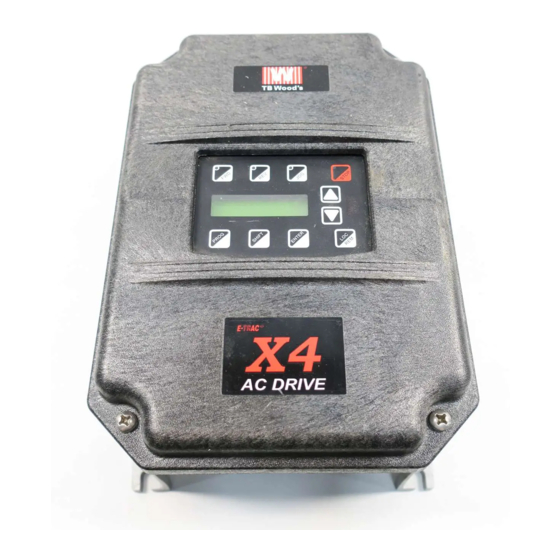
- Page 1 Form 1428D AC Drive User’s Manual TB Wood’s Incorporated Chambersburg, PA USA...
- Page 2 Free Warranty removes the “burden of guilt” and promises to quickly replace any failed product. TB Wood’s Incorporated warrants the X4 Series AC drive to be free of defects in parts or workmanship for a period of three (3) years from the date of manufacture, or two (2) years from the date of installation, whichever comes first.
-
Page 3: Summary Of X4 Parameters
= cannot change in Run Bold type = Level 1 parameter Summary of X4 Parameters Parameter Name Options Default User Setting See Page Model Number Model Dependent Read-only Software Rev 0.00-99.99 Read-only Rated Current 0.0-200.0 A Read-only Serial No. 1... - Page 4 X4 AC Drive User’s Manual Summary of X4 Parameters Parameter Name Options Default User Setting See Page Accel Time 2 0.1-3200.0 sec 3.0 sec Decel Time 2 0.1-3200.0 sec 3.0 sec DC Inject Config text string DC at Stop DC Inject Time 0.0-5.0 sec...
- Page 5 X4 AC Drive User’s Manual Summary of X4 Parameters Parameter Name Options Default User Setting See Page Relay 1 Select text string Drv Fault Relay 2 Select text string Drive Run DO1 Select text string Drv Ready DO2 Select text string...
- Page 6 X4 AC Drive User’s Manual Summary of X4 Parameters Parameter Name Options Default User Setting See Page Seq Cntl 5 00000000000 Seq Cntl 6 00000000000 Seq Cntl 7 00000000000 Seq Cntl 8 00000000000 Seq Cntl 9 00000000000 Seq Count 1...
-
Page 7: Table Of Contents
4.4 Terminals Found on the X4 Power Board ....... . . - Page 8 4.6 Terminals Found on the X4 Control Board ....... .
-
Page 9: Chapter 1: Introduction
Chapter 1: Introduction 1.1 Product Overview Although the X4 AC drive is small in size, it is big on performance. It is an economical yet powerful solution for many industrial applications. It features remote communications capability (using ® Modbus protocol), a keypad for easy configuration, and standard NEMA 4X / IP66 and NEMA 12 / IP54 enclosures that eliminate the need for mounting in a separate enclosure. -
Page 10: User's Manual Publication History
1428 First release Minor corrections throughout manual. Clarification of technical information and specifications. Added X4 models for Frame Size 2. March 2006 1428B Reformatted to larger page-size document; separated appendices from manual to be available on the TB Wood’s web site (www.tbwoods.com). -
Page 11: Chapter 2: Technical Characteristics
Chapter 2: Technical Characteristics Interpreting Model Numbers The model number of the X4 AC drive appears on the shipping carton label and on the technical data label affixed to the model. The information provided by the model number is shown below:... -
Page 12: Power And Current Ratings
X4 AC Drive User’s Manual Chapter 2: Technical Characteristics Power and Current Ratings 115 Vac Ratings Normal Duty Input current (A) Output current (A) Heavy Duty Input current (A) Output current (A) Model number 115 Vac 230 Vac 115 Vac... -
Page 13: Environmental Specifications
X4 AC Drive User’s Manual Chapter 2: Technical Characteristics 575 Vac Ratings Normal Duty Input current (A) Output current (A) Heavy Duty Input current (A) Output current (A) Model number 575 Vac 575 Vac 575 Vac 575 Vac X4C50010C 0.75 0.5 0.37... -
Page 14: Electrical Specifications
X4 AC Drive User’s Manual Chapter 2: Technical Characteristics Electrical Specifications X4C1Sx models: 115 Vac 1 phase, +/- 10% X4C2x models: 200-230 Vac, 3 phase, +/- 15% Input voltage X4C4x models: 380-460 Vac, 3 phase, +/- 15% X4C5x models: 575Vac, 3 phase, +/-15% Line frequency 50 / 60 Hz ±2 Hz... -
Page 15: Dimensions And Weights
Dimensions and Weights Table 2-1 lists dimensions and weights for the X4 frame size 0, 1, 2, and 3 models. Dimensions and weights for the X4 frame size 4 and 5 models are shown in Table 2-2 on page 8. - Page 16 7.45 (189) 7.45 (189) 10.23 (260) 10.23 (260) 1.94 (49) 1.94 (49) 1.86 (47) 1.86 (47) Weight 95.0 (43.10)) 305.0 (138.35) lb (kg) Figure 2-1: X4 Frame Size 0 Models 1428D-0607 - 8 - © 2007 TB Wood’s All Rights Reserved...
- Page 17 X4 AC Drive User’s Manual Chapter 2: Technical Characteristics Figure 2-2: X4 Frame Size 1 Models Figure 2-3: X4 Frame Size 2 Models 1428D-0607 - 9 - © 2007 TB Wood’s All Rights Reserved...
- Page 18 X4 AC Drive User’s Manual Chapter 2: Technical Characteristics F (8) PLACES M (2) PLACES N (3) PLACES Figure 2-4: X4 Frame Size 3 Models F (8) PLACES N (2) PLACES M(2) PLACES S (1) PLACES Figure 2-5: X4 Frame Size 4 Models...
- Page 19 X4 AC Drive User’s Manual Chapter 2: Technical Characteristics F (8) PLACES N(2) PLACES M (2) PLACES S (1) PLACE Figure 2-6: X4 Frame Size 5 Models 1428D-0607 - 11 - © 2007 TB Wood’s All Rights Reserved...
-
Page 20: Chapter 3: Receiving And Installation
3.2 Installation Precautions Improper installation of the X4 AC drive will greatly reduce its life. Be sure to observe the following precautions when selecting a mounting location. Failure to observe these precautions may void the warranty! See the inside front cover of this manual for more information about the warranty. -
Page 21: Dissipation Requirements
X4 AC Drive User’s Manual Chapter 3: Receiving and Installation 3.3 Dissipation Requirements Table 3-1: Dissipation Requirement for X4 Models (Page 1 of 2) Required Dissipation for Models Required Dissipation When Fins are Model Entirely Inside an Enclosure at Rated... -
Page 22: Cover Assembly And Torque Specifications
2282 X4C52000C 3043 3.4 Cover Assembly and Torque Specifications Figure 3-1 shows the locations of the X4 cover screws. The torque range for the X4 covers is 18-26 in/lbs. Cover screw locations Cover screw locations Figure 3-1: X4 Cover Assembly and Screw Locations Torque specifications for control terminals and power terminals are listed in “General Wiring... -
Page 23: Serial Number Label
3.6 Conduit Usage The X4 drive in the NEMA 4X / IP66 enclosure is rated for 1000 psi washdown from 6 inches. To keep this rating, the use of a sealed conduit is required. The use of a Romex-type conduit will not prevent water entry into the enclosure. -
Page 24: Chapter 4: Connections
Chapter 4: Connections DANGER HAZARDOUS VOLTAGE • Read and understand this manual in its entirety before installing or operating the X4 AC drive. Installation, adjustment, repair, and maintenance of these drives must be performed by qualified personnel. • Disconnect all power before servicing the drive. WAIT 5 MINUTES until the DC bus capacitors discharge. -
Page 25: Introduction
See Chapter 2 for the continuous output ratings for the drive. • Grounding must be in accordance with NEC and CEC. If multiple X4 drives are installed near each other, each must be connected to ground. Take care not to form a ground loop. -
Page 26: Considerations For Control Wiring
See “Power and Current Ratings” on page 4 for the allowable fluctuation of AC line voltage for your particular X4 model. A supply voltage above or below the limits given in the table will cause the drive to trip with either an overvoltage or undervoltage fault. -
Page 27: Line Capacity
Therefore, ensure that the voltage rating of the motor matches the applied line voltage. 4.3.2 Line Capacity If the source of AC power to the X4 AC drive is greater than 10 times the kVA rating shown in Table 4-3 below, an isolation transformer or line reactor is recommended. Consult the factory for assistance in sizing the reactor. -
Page 28: Ground Fault Circuit Interrupters
Chapter 4: Connections 4.3.5 Ground Fault Circuit Interrupters X4 drives rated for 115 Vac are not designed to operate with ground fault circuit interrupters (GFCI). The GFCI breakers are designed for residential use to protect personnel from stray currents to ground. -
Page 29: Typical Power Connections
X4 AC Drive User’s Manual Chapter 4: Connections and on the terminal strip for models 40 HP and larger. See page 23 for specific information about dynamic braking. Figure 4-1: X4 Power Terminals Figure 4-2: Power Terminals on Higher-HP Models 4.4.2 Typical Power Connections... - Page 30 It is necessary to provide fuses and a disconnect switch for the input AC line in accordance with all applicable electrical codes. The X4 AC drive is able to withstand a 150% overload for 60 seconds for heavy duty rating, and 120% overload for normal duty rating.
-
Page 31: Dynamic Braking
— Dynamic Braking The X4 AC drive is supplied with an integrated dynamic braking (DB) resistor, and is designed to have adequate dynamic braking for most applications. In cases where short stopping times or high inertia loads require additional braking capacity, install an external resistor. - Page 32 X4 AC Drive User’s Manual Chapter 4: Connections Table 4-6: X4 Dynamic Braking Capacity (Page 1 of 2) (* Note that the asterisked X4 model numbers cannot have external braking added) Standard Standard DB % Min. Allowed Max. Peak Max. Ext. DB %...
-
Page 33: Terminals Found On The X4 Control Board
Terminals Found on the X4 Control Board 4.6.1 Description of the Control Terminals Figure 4-3 shows the control terminals found on the I/O board of the X4 AC drive. See page 6 for specifications. Table 4-7 on page 26 describes the control terminals. - Page 34 X4 AC Drive User’s Manual Chapter 4: Connections Table 4-7: Description of X4 Control Terminals (Page 1 of 2) Terminal Description Vmet Analog output 1, which is a dedicated voltage output. The default signal range is from 0 to 10 Vdc (5 mA maximum). It is proportional to the variable configured by parameter (see page 65).
- Page 35 X4 AC Drive User’s Manual Chapter 4: Connections Table 4-7: Description of X4 Control Terminals (Page 2 of 2) Terminal Description Run/Jog Selector. When this terminal is connected to +24 or common (depending upon Active Logic setting), momentarily connecting either FWD or REV to +24 results in a latched run mode (3-wire operation).
-
Page 36: Typical Connection Diagrams For Digital Inputs
X4 AC Drive User’s Manual Chapter 4: Connections 4.6.2 Typical Connection Diagrams for Digital Inputs Typical connection for 2-wire control Typical connection for 3-wire control Figure 4-4: Connections for 2-wire and 3-wire Control Table 4-8: Selection of Preset Speeds PS3 (Bit 3) -
Page 37: Typical Connection Diagrams For Analog Inputs
X4 AC Drive User’s Manual Chapter 4: Connections 4.6.3 Typical Connection Diagrams for Analog Inputs Figure 4-6: Connections for Speed Potentiometer Figure 4-7: Connections for Process Signal 4.6.4 Typical Connection Diagrams for Analog Outputs Figure 4-8: Connections for Process Meters... -
Page 38: Chapter 5: Keypad Operation And Programming
Chapter 5: Keypad Operation and Programming Introduction The X4 AC drive is pre-programmed to run a standard, 4-pole AC induction motor. For many applications, the drive is ready for use right out of the box with no additional programming needed. -
Page 39: Keypad Operation
Chapter 5: Programming with the X4 Keypad Keypad Operation Parameter 201, Input Mode (see page 52), determines whether the X4 AC drive accepts its Run/ Stop and speed commands from the digital keypad or from the input terminals. Table 5-1 describes the function of the keys in Operation mode. - Page 40 The display will show “stored” for one second indicating that the new value has been entered into memory. NOTE: The X4 unit allows you to view only those parameters that have changed. If you press keypad keys ENTER and PROGram simultaneously, only those parameters that have been changed from the factory defaults will be shown.
-
Page 41: Lcd Displays
X4 AC Drive User’s Manual Chapter 5: Programming with the X4 Keypad LCD Displays The X4 drive’s digital keypad display provides information such as source of drive control, status, mode, and access rights. 5.3.1 Control The first 3 characters of the display show the source of control for the drive:... - Page 42 A stop command was given from the keypad when the keypad was not the active control source. To Kpd Stop remove this condition, the run signal to the drive must be removed. Table 5-5 shows X4 keypad warning messages that may appear during operation: Table 5-5: Keypad Warnings Message...
-
Page 43: Rights
X4 AC Drive User’s Manual Chapter 5: Programming with the X4 Keypad 5.3.3 Rights After Program mode is entered, the operator’s access rights are displayed: Display Values This indicates that while in Programming mode, parameter data can be changed. If the drive is in Run mode (FWD or REV) when the PROG key was pressed, ACCESS parameters can be viewed, but not changed. -
Page 44: Programming
X4 AC Drive User’s Manual Chapter 5: Programming with the X4 Keypad Programming 5.5.1 Accessing Parameters When PROG (or SHIFT+PROG) is pressed after application of power or a fault reset, parameter 201, Input Mode, is always the first parameter displayed. Figure 5-3 shows a typical programming display. -
Page 45: Restoring Factory Settings
801, Program Number (page 68). 5.5.5 Viewing Parameters That Have Changed The X4 unit allows you to view only those parameters that have changed. If you press keypad keys ENTER and PROGram simultaneously, only those parameters that have been changed from the factory defaults will be shown. -
Page 46: Activating Automatic Rs Measurement Via Serial Link (Modbus)
X4 AC Drive User’s Manual Chapter 5: Programming with the X4 Keypad 7. Start the RS Measurement by pressing the FWD key. The measurement can only be made with the FWD key. The FWD / REV terminals and the REV key will not work. -
Page 47: Chapter 6: Using Macro Mode And Getting A Quick Start
Chapter 6: Using Macro Mode and Getting a Quick Start A special Macro programming mode is available with the X4 series of AC drives. The Macro programming mode allows you to customize quickly the most common parameters for your application in the Level 1 group. Macro mode provides special parameters for activating modes of operation by macros, program sequencer, or serial communications. -
Page 48: Description Of Parameters Used In Macro Mode
Parameters 490, 491, and 492 are used only in the Macro mode. Parameters 509, 510, 511, 801, and 810 are used in both Macro and Level 2 programming. X4 parameters are described in “Chapter 7: X4 Parameters” on page 49 of this manual. - Page 49 X4 AC Drive User’s Manual Chapter 6: Using Macro Mode / Quick Start Range: 0-24000 rpm 511 Rated Mtr RPM Default: 1750 rpm Level 2, Macro This parameter replaces the slip compensation parameter setting of the drive so the user does not need to calculate it.
-
Page 50: Macro Mode Applications And Included Parameters
X4 AC Drive User’s Manual Chapter 6: Using Macro Mode / Quick Start Macro Mode Applications and Included Parameters The tables below list the different applications and the Level 1 parameters included in the macro for that application. The Factory Application macro is the core package (listed in Table 6-1); the other macros include the Factory Application macro parameters as well as the ones listed in their respective tables (Tables 6-2, 6-3, 6-4, 6-5, and 6-6). - Page 51 X4 AC Drive User’s Manual Chapter 6: Using Macro Mode / Quick Start Table 6-2: Fan Application Macro (Core Factory Application from Table 6-1, plus the following parameters) Para. # Parameter Name Default See Page Stop Key Remote Coast Ref Select...
- Page 52 X4 AC Drive User’s Manual Chapter 6: Using Macro Mode / Quick Start Table 6-3: Fan with PI Application Macro (Core Factory Application from Table 6-1, plus the following parameters) Para. # Parameter Name Default See Page Stop Key Remote...
- Page 53 X4 AC Drive User’s Manual Chapter 6: Using Macro Mode / Quick Start Table 6-4: Pump Application Macro (Core Factory Application from Table 6-1, plus the following parameters) Para. # Parameter Name Default See Page Stop Key Remote Coast Ref Select...
- Page 54 X4 AC Drive User’s Manual Chapter 6: Using Macro Mode / Quick Start Table 6-5: Pump with PI Application Macro (Core Factory Application from Table 6-1, plus the following parameters) Para. # Parameter Name Default See Page Stop Key Remote...
- Page 55 X4 AC Drive User’s Manual Chapter 6: Using Macro Mode / Quick Start Table 6-6: Vector Application Macro (Core Factory Application from Table 6-1, plus the following parameters) Para. # Parameter Name Default See Page V/Hz Select Vector Rated Mtr Volt...
-
Page 56: Quick Start
T1/U, T2/V, or T3/W. The X4 drive is preset to run a typical NEMA B 4-pole induction motor to a maximum speed of 60.0 Hz with both acceleration and deceleration times set to 5.0 seconds. -
Page 57: Chapter 7: X4 Parameters
Level 1 Parameters The most commonly configured X4 parameters are stored in a group named Level 1. This group is easily accessed by pressing the PROG key as described in “Chapter 5: Keypad Operation and Programming”... -
Page 58: Description Of Parameters
Chapter 7: X4 Parameters Description of Parameters Table 7-2 lists the X4 parameters in the order in which they appear in the keypad display. For each parameter, the table lists the default value and range and also describes the use of the parameter. - Page 59 X4 AC Drive User’s Manual Chapter 7: X4 Parameters Table 7-2: Description of X4 Parameters (Page 2 of 26) Range: 0.0 to 400.0 Hz 102 Output Freq Read-Only Levels 1,2 Parameter 102, the Output Frequency parameter, shows the frequency being applied to the motor connected to the drive (ramp).
- Page 60 X4 AC Drive User’s Manual Chapter 7: X4 Parameters Table 7-2: Description of X4 Parameters (Page 3 of 26) Range: n/a 201 Input Mode Default = Local only Levels 1,2 Parameter 201, the Input Mode parameter, configures local and remote control of the Start/Stop source and the reference source.
- Page 61 Cin terminal (configured by parameter 208) Vin2 Vin2 terminal (configured by parameter 211) Vin1 6FS Vin1 terminal with 6x pulse train from an X4, WFC, WF2 drive Vin1 48FS Vin1 terminal with 48x pulse train from an X4, WFC, WF2 drive Vin1+Cin...
- Page 62 X4 AC Drive User’s Manual Chapter 7: X4 Parameters Table 7-2: Description of X4 Parameters (Page 5 of 26) Range: 10.0 to 200.0% 207 Vin1 Span Default = 100% Level: 2 Parameter 207, the Vin1 Span parameter, is used to alter the input range (span) of the input signal for analog input Vin1 that will affect speed or torque limit functions.
- Page 63 X4 AC Drive User’s Manual Chapter 7: X4 Parameters Table 7-2: Description of X4 Parameters (Page 6 of 26) Range: 0 to 1000 ms 215 Cin Filter Time Default = 20 ms Level: 2 This parameter configures the time constant of a filter of the Cin analog input. When the parameter value is set to 0 ms, there is no software filtering of the analog input.
- Page 64 X4 AC Drive User’s Manual Chapter 7: X4 Parameters Table 7-2: Description of X4 Parameters (Page 7 of 26) Range: 0.0 to 5.0 Hz 309 Cut-Off Freq Default: 0.0 Hz Level 2 This parameter sets the point where the drive no longer attempts to spin the motor. The range of this parameter is 0.0- 5.0 Hz.
- Page 65 DC injection braking may be used to stop the motor more quickly than is possible by either a ramp-to-stop or a coast- to-stop. The X4 drive allows DC braking to be initiated either when a digital input assigned to DC braking becomes true, when a specified frequency is reached, or when either of these events occurs.
- Page 66 X4 AC Drive User’s Manual Chapter 7: X4 Parameters Table 7-2: Description of X4 Parameters (Page 9 of 26) Range: 0-2 410 DB Config Default: DB Internal Level 2 Determines whether an external or internal dynamic brake is utilized or disabled. The drive provides an internal dynamic brake (DB) to assist in stopping.
- Page 67 X4 AC Drive User’s Manual Chapter 7: X4 Parameters Table 7-2: Description of X4 Parameters (Page 10 of 26) Range: 0 to 7 501 V/Hz Select Default: Linear Fxd Level 2 The V/Hz Characteristic Selection parameter determines the characteristic of the V/Hz curve and whether any boost will be applied at starting.
- Page 68 The X4 AC drive provides the capability to configure four prohibited frequency bands. Parameter 504 (Skip Freq Band), the Skip Frequency Band parameter, sets the width of the band above and below each of the prohibited frequencies set in parameters 505, 506, 507, and 508 (Skip Freq 1,2,3, 4).
- Page 69 X4 AC Drive User’s Manual Chapter 7: X4 Parameters Table 7-2: Description of X4 Parameters (Page 12 of 26) Range: n/a 516 Slip Comp Enable Default: No Level 1,2 The following data values may be assigned to this parameter: Parameter Value...
- Page 70 X4 AC Drive User’s Manual Chapter 7: X4 Parameters Table 7-2: Description of X4 Parameters (Page 13 of 26) Range: 0 - 200% 523 Id Percent Default: Read-only Level 2 This parameter shows the Flux producing current (as a percentage of motor rated current) that is being applied to the drive.
- Page 71 Default: Fixed Lvls Level 2 The X4 drive provides a Current Limit feature. With this feature enabled, the drive’s frequency is automatically reduced when operating in motoring mode to keep the measured torque within limits. When operating in regenerative mode, the output frequency can be automatically increased for the same reason.
- Page 72 Default: Std Ind 60s Level 2 Two parameters in the X4 work together to configure how the motor timed overload operates: Parameter 510 (Rated Mtr FLA) and Parameter 610 (Timed OL Select). Parameter 510 (Rated Mtr FLA) should be configured to the value on the nameplate of the motor. This value is used in calculating the percentage of current at which the drive is operating.
- Page 73 X4 AC Drive User’s Manual Chapter 7: X4 Parameters Table 7-2: Description of X4 Parameters (Page 16 of 26) Range: n/a 700 Vmet Config Default: Freq Out Levels 1,2 This parameter configures the analog signal that will be applied to the Vmet output pin.
- Page 74 SeqOut-10 SeqOut-11 See “Using the X4 Program Sequencer” on page 75 for more information. ARCTIC When a digital output is configured to use this option, the output will be active when the Arctic Mode is turning on the DB resistor.
- Page 75 X4 AC Drive User’s Manual Chapter 7: X4 Parameters Table 7-2: Description of X4 Parameters (Page 18 of 26) Default: Preset 1 721 DI1 Configure Default: Preset 2 722 DI2 Configure Range: n/a 723 DI3 Configure Default: Preset 3 Level 2...
- Page 76 X4 AC Drive User’s Manual Chapter 7: X4 Parameters Table 7-2: Description of X4 Parameters (Page 19 of 26) Range: n/a 727 MOL Configure Default: MOL Level 2 This parameter serves as the selection for the operation of the MOL terminal. The polarity of the MOL digital iinput is still determined by Parameter 726, MOL Polarity.
- Page 77 X4 AC Drive User’s Manual Chapter 7: X4 Parameters Table 7-2: Description of X4 Parameters (Page 20 of 26) Range: n/a 802 Start Options Default: LS Lockout Level 2 The Start Options parameter configures the Line Start Lockout functionality of the drive. All data values ending with “2”...
- Page 78 Level 2 The Master / Follower Speed Ratio parameter allows the pulse train output of one X4 series drive (master) to be used to control the speed of up to 8 other follower drives. The output of each follower can be individually programmed, or trimmed “ON-THE-FLY”...
- Page 79 X4 AC Drive User’s Manual Chapter 7: X4 Parameters Table 7-2: Description of X4 Parameters (Page 22 of 26) Range: 0.0%-200.0% 814 Display Status Default: Drive Load Level 2 This parameter allows configuration of the additional parameter status field on the operate screen. The following fields...
- Page 80 X4 AC Drive User’s Manual Chapter 7: X4 Parameters Table 7-2: Description of X4 Parameters (Page 23 of 26) Range: 0-2000 852 PI Prop Gain Default: 0 Level 2 The PI Proportional Gain parameter configures the proportional gain that is applied to the PI control.
- Page 81 X4 AC Drive User’s Manual Chapter 7: X4 Parameters Table 7-2: Description of X4 Parameters (Page 24 of 26) Range: n/a 904 SIO Cntl Word Default: 0x0000 Level 2 (SIO) The SIO Control Word parameter allows control of the drive through Modbus communications.
- Page 82 937 Seq Cntl 7 938 Seq Cntl 8 939 Seq Cntl 9 These parameters each provide a 10-bit binary status display. See “Using the X4 Program Sequencer” on page 75. The following bits are used with each of these parameters: Bit 0-2=Speed Sel...
-
Page 83: Using The X4 Program Sequencer
See “Using the X4 Program Sequencer” on page 75. Using the X4 Program Sequencer The X4 AC drive offers functionality that allows users to program up to nine independent operation states of the drive. This functionality is called the “program sequencer” because it allows the drive to sequence through the operation states programmed by the user. - Page 84 Note: If Input Mode is configured to any of the EMOP options, the sequencer is not available. Keypad Control (Activation) of the X4 Program Sequencer When activating or controlling the X4 Program Sequencer from the keypad, pressing the FWD key commands the drive to cycle through the programmed states of the sequencer one time only (one- shot operation).
-
Page 85: Sequencer State Configuration Overview
If the sequencer is actively running and the Enter key is pressed from the Operate screen of the X4 keypad, the sequencer will dwell in the current state (it will never advance to the next state). While the sequencer is dwelling, a warning of “Seq Dwell”... - Page 86 Chapter 7: X4 Parameters X4 Sequencer Speed Selection Table 7-5 gives more information on the speed selection options available in the X4 sequencer by programming bits 0, 1, and 2 of each state’s control parameter. The options include any Preset Speed, Max Frequency, or allowing the reference to be determined in the normal X4 control path.
- Page 87 X4 AC Drive User’s Manual Chapter 7: X4 Parameters programmed into this parameter can be from 0 to 65,535, and can represent time, pulse counts, analog voltage thresholds, analog current thresholds, or digital comparison values. Table 7-6: Seq Count Definition Based on Cntl Parameter Configuration...
-
Page 88: Sequencer Status Indicators
X4 AC Drive User’s Manual Chapter 7: X4 Parameters 7.4.4 Sequencer Status Indicators When the sequencer is enabled, the control path indication field on the keypad will indicate SQx, where x represents the active state of the sequencer. A sample operate screen (where the sequencer... - Page 89 X4 AC Drive User’s Manual Chapter 7: X4 Parameters Required parameter modifications for this program are provided in Table 7-8, with explanations. Table 7-8: Required Parameter Settings for Sample Sequencer Program Parameter Value Explanation Seq Appl “1 sec Base” Sets 1 second time increments DI1 Configure “Seq1”...
- Page 90 X4 AC Drive User’s Manual Chapter 7: X4 Parameters Worksheet for Sequencer Program Setup 1428D-0607 - 82 - © 2007 TB Wood’s All Rights Reserved...
-
Page 91: Chapter 8: Troubleshooting
Chapter 8: Troubleshooting 8.1 X4 Fault Codes Table 8-1 shows the fault codes that may be displayed during X4 AC drive operation, along with suggestions for recovering from the fault condition. When faults occur, you can access the status parameters that are saved along with the fault (Advanced Fault history). - Page 92 X4 AC Drive User’s Manual Chapter 8: Troubleshooting Table 8-1: X4 Fault Codes (Page 2 of 5) Adv. Fault Code Fault Display Description Code Explanation Suggestions for Recovery Control board is not reading the Consult factory for repair or Model ID...
- Page 93 X4 AC Drive User’s Manual Chapter 8: Troubleshooting Table 8-1: X4 Fault Codes (Page 3 of 5) Adv. Fault Code Fault Display Description Code Explanation Suggestions for Recovery Check that ambient temperature does not exceed drive’s rating. • The temperature of the heatsink Check for fan operation exceeded a temperature limit.
- Page 94 X4 AC Drive User’s Manual Chapter 8: Troubleshooting Table 8-1: X4 Fault Codes (Page 4 of 5) Adv. Fault Code Fault Display Description Code Explanation Suggestions for Recovery This fault occurs when the drive is in a serial link control path and the...
- Page 95 X4 AC Drive User’s Manual Chapter 8: Troubleshooting Table 8-1: X4 Fault Codes (Page 5 of 5) Adv. Fault Code Fault Display Description Code Explanation Suggestions for Recovery There is a problem with the heat sink fan. There is a problem with the internal fan.
- Page 96 WE: TB Wood’s, Inc. 440 North Fifth Avenue Chambersburg, PA 17201 USA hereby declare that the products: Product Name: X4 Series Model Number: X4C1S010C, X4C20010C, X4C20020C, X4C20030C, X4C20050C, X4C20075C, X4C20100C, X4C20150C, X4C20200C, X4C20300C, X4C40010C, X4C40020C, X4C40030C, X4C40050C, X4C40075C, X4C40100C, X4C40150C, X4C40200C,...
- Page 98 USA SALES TB Wood’s Incorporated Headquarters 440 North Fifth Avenue Chambersburg, Pennsylvania 17201-1778 Telephone: 888-TBWOODS or 717-264-7161 FAX: 717-264-6420 Website: www.tbwoods.com INTERNATIONAL SALES Canada T.B. Wood’s Canada Ltd. 750 Douro Street Stratford, Ontario, Canada N5A 6V6 Telephone: 519-271-5380 FAX: 519-271-3094 Germany Berges electronic GmbH Industriestraße 13 D-51709 Marienheide, Germany Telephone: 49-2264-17-0...
Need help?
Do you have a question about the X4 and is the answer not in the manual?
Questions and answers