Table of Contents
Advertisement
Installer's Guide
Convertible Air Handlers
2 — 5 Ton
TEM6A0B24H21S
TEM6A0B30H21S
TEM6A0C36H31S
TEM6A0C42H41S
TEM6A0C48H41S
TEM6A0D48H41S
TEM6A0C60H51S
TEM6A0D60H51S
Only qualified personnel should install and service the equipment. The installation, starting up, and servicing of heating, ventilating, and
air-conditioning equipment can be hazardous and requires specific knowledge and training. Improperly installed, adjusted or altered
equipment by an unqualified person could result in death or serious injury. When working on the equipment, observe all precautions in the
literature and on the tags, stickers, and labels that are attached to the equipment.
January 2016
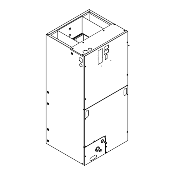
The TEM6 series air handler is designed for installation in a closet,
utility room, alcove, basement, crawlspace or attic. These versatile
units are applicable to air conditioning and heat pump
applications. Several models are available to meet the specific
requirements of the outdoor equipment. Field installed electric
resistance heaters are available.
S S A A F F E E T T Y Y W W A A R R N N I I N N G G
18-GF74D1-1F-EN
Advertisement
Table of Contents

Related Manuals for Ingersoll-Rand TEM6A0B24H21S


Summary of Contents for Ingersoll-Rand TEM6A0B24H21S
- Page 1 Installer’s Guide Convertible Air Handlers 2 — 5 Ton TEM6A0B24H21S TEM6A0B30H21S TEM6A0C36H31S TEM6A0C42H41S TEM6A0C48H41S TEM6A0D48H41S TEM6A0C60H51S TEM6A0D60H51S The TEM6 series air handler is designed for installation in a closet, utility room, alcove, basement, crawlspace or attic. These versatile units are applicable to air conditioning and heat pump applications.
- Page 2 SAFETY SECTION AIR HANDLERS I I m m p p o o r r t t a a n n t t : : This document contains a wiring diagram, W W A A R R N N I I N N G G a parts list, and service information.
- Page 3 S S A A F F E E T T Y Y S S E E C C T T I I O O N N A A I I R R H H A A N N D D L L E E R R S S W W A A R R N N I I N N G G N N o o t t e e : : Air handlers have been evaluated in accordance with the Code of Federal Regulations, Chapter...
-
Page 4: Table Of Contents
Table of Contents Features ........5 Heater Pressure Drop Table. -
Page 5: Features
Features Table 1. Standard Features I I M M P P O O R R T T A A N N T T : : The downflow sub-base may be required with electric heat applications. • MULTI-POSITION UPFLOW, DOWNFLOW, HORIZONTAL LEFT See minimum clearance table. - Page 6 F F e e a a t t u u r r e e s s 5. R R e e f f r r i i g g e e r r a a n n t t P P i i p p i i n n g g Figure 2.
- Page 7 F F e e a a t t u u r r e e s s Consult all schematic and pictorial wiring diagrams or AC single stage heating/cooling with electric of this unit and the outdoor equipment to determine heat. The thermostat will energize the fan on a compatibility of wiring connections and to demand for heat or cool.
- Page 8 F F e e a a t t u u r r e e s s In the heating mode, the reversing valve of the 13. O O p p e e r r a a t t i i o o n n a a l l a a n n d d C C h h e e c c k k o o u u t t P P r r o o c c e e d d u u r r e e s s outdoor unit is not energized.
-
Page 9: Field Wiring
Field Wiring Sing le St age, C o o lin g O n ly Sing le St age, HP Outdoor Outdoor The rm o s t a t Air H andler The rm o s t a t Air H andler Un it Un it 24 VAC HOT... - Page 10 F F i i e e l l d d W W i i r r i i n n g g 2 St age, 2 Step, Coo lin g O n ly 2 St age, 2 Step, HP Outdoor Outdoor The rm o s t a t Air H andler...
-
Page 11: Electrical Data
Electrical Data 18-GF74D1-1F-EN... -
Page 12: Performance And Electrical Data
Performance and Electrical Data Table 4. Air Flow Performance TEM6A0B24, TEM6A0B30 COOLING AIRFLOW PERFORMANCE, WET COIL, NO FILTER, NO HEATER OUTDOOR DIP SWITCH SETTING EXTERNAL STATIC PRESSURE SPEED AIRFLOW AIRFLOW UNIT SIZE SETTING SETTING POWER (TONS) 353 CFM/ Watts 401 CFM/ NORMAL Watts 451 CFM/... - Page 13 P P e e r r f f o o r r m m a a n n c c e e a a n n d d E E l l e e c c t t r r i i c c a a l l D D a a t t a a Table 6.
- Page 14 P P e e r r f f o o r r m m a a n n c c e e a a n n d d E E l l e e c c t t r r i i c c a a l l D D a a t t a a Table 8.
- Page 15 P P e e r r f f o o r r m m a a n n c c e e a a n n d d E E l l e e c c t t r r i i c c a a l l D D a a t t a a Table 10.
- Page 16 P P e e r r f f o o r r m m a a n n c c e e a a n n d d E E l l e e c c t t r r i i c c a a l l D D a a t t a a Table 12.
- Page 17 P P e e r r f f o o r r m m a a n n c c e e a a n n d d E E l l e e c c t t r r i i c c a a l l D D a a t t a a Table 14.
- Page 18 P P e e r r f f o o r r m m a a n n c c e e a a n n d d E E l l e e c c t t r r i i c c a a l l D D a a t t a a Table 15.
-
Page 19: Minimum Airflow Cfm
Minimum Airflow CFM TEM6A0B24H21S, TEM6A0B30H21S Heater Minimum Heater Airflow CFM With Heat Pump Without Heat Pump BAYHTR1504BRKC, BAYHTR1504LUGB BAYHTR1505BRKC, BAYHTR1505LUGB BAYHTR1508BRKC, BAYHTR1508LUGB BAYHTR1510BRKC, BAYHTR1510LUGB BAYHTR1516BRKA 1050 BAYHTR3510LUGC BAYHTR3515LUGC TEM6A0C36H31S, TEM6A0C42H41S Heater Minimum Heater Airflow CFM With Heat Pump Without Heat Pump... - Page 20 M M i i n n i i m m u u m m A A i i r r f f l l o o w w C C F F M M TEM6A0B24H21, TEM6A0B30H21 Airflow Performance with Auxiliary Heat Dip Switch Settings Airflow Settings Nominal Airflow...
-
Page 21: Outline Drawing
Outline Drawing PRODUCT DIMENSIONS Gas Line Flow Air Handler Model Braze Control TEM6A0B24, 30 46.77 18.50 16.50 16.75 4.68 7.33 20.09 TEM6A0C36, 42 51.27 23.50 21.50 21.75 7.01 9.66 24.59 TEM6A0C48, 60 55.87 23.50 21.50 21.75 4.68 9.66 27.19 TEM6A0D48, 60 53.87 26.50 24.50... -
Page 22: Heater Pressure Drop Table
Heater Pressure Drop Table Number of Racks Heater Racks Airflow Heater Model No. of Racks Air Pressure Drop — Inches W.G. BAYHTR1504 1800 0.02 0.04 0.06 0.14 BAYHTR1505 1700 0.02 0.04 0.06 0.14 BAYHTR1508 1600 0.02 0.04 0.06 0.13 BAYHTR1510 1500 0.02 0.04... -
Page 23: Coil Conversion Instructions
Coil Conversion Instructions Table 16. Downflow Figure 5. All other models Follow the conversion steps when installing the air handler in downflow configuration. Remove the front panels from the air handler. The coil and line set panel do not need to be separated. Remove the fasteners on both sides of the coil. - Page 24 C C o o i i l l C C o o n n v v e e r r s s i i o o n n I I n n s s t t r r u u c c t t i i o o n n s s Table 16.
- Page 25 C C o o i i l l C C o o n n v v e e r r s s i i o o n n I I n n s s t t r r u u c c t t i i o o n n s s Table 16.
- Page 26 C C o o i i l l C C o o n n v v e e r r s s i i o o n n I I n n s s t t r r u u c c t t i i o o n n s s Table 16.
- Page 27 C C o o i i l l C C o o n n v v e e r r s s i i o o n n I I n n s s t t r r u u c c t t i i o o n n s s Table 16.
-
Page 28: Coil Conversion
C C o o i i l l C C o o n n v v e e r r s s i i o o n n I I n n s s t t r r u u c c t t i i o o n n s s Coil Conversion Table 17. - Page 29 C C o o i i l l C C o o n n v v e e r r s s i i o o n n I I n n s s t t r r u u c c t t i i o o n n s s Table 17.
- Page 30 C C o o i i l l C C o o n n v v e e r r s s i i o o n n I I n n s s t t r r u u c c t t i i o o n n s s Table 17.
- Page 31 C C o o i i l l C C o o n n v v e e r r s s i i o o n n I I n n s s t t r r u u c c t t i i o o n n s s Table 17.
- Page 32 C C o o i i l l C C o o n n v v e e r r s s i i o o n n I I n n s s t t r r u u c c t t i i o o n n s s Table 17.
- Page 33 C C o o i i l l C C o o n n v v e e r r s s i i o o n n I I n n s s t t r r u u c c t t i i o o n n s s Table 17.
- Page 34 C C o o i i l l C C o o n n v v e e r r s s i i o o n n I I n n s s t t r r u u c c t t i i o o n n s s Table 17.
- Page 35 C C o o i i l l C C o o n n v v e e r r s s i i o o n n I I n n s s t t r r u u c c t t i i o o n n s s Table 17.
-
Page 36: Checkout Procedures
Checkout Procedures The final phase of the installation is the system Checkout Procedures. The following list represents the most common items covered in a Checkout Procedure. Confirm all requirements in this document have been met. All wiring connections are tight and properly secured. Supply registers and return grilles are open, unobstructed, and air filter is installed.
Need help?
Do you have a question about the TEM6A0B24H21S and is the answer not in the manual?
Questions and answers
Where is the best spot to install a UV-C light in an Ingersoll Rand Air handler model TEM6A0C36H31S?