Table of Contents
Advertisement
Advertisement
Table of Contents

Related Manuals for Woodland Mills WC88


Summary of Contents for Woodland Mills WC88
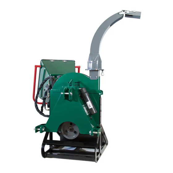
- Page 1 WC88 PTO WOOD CHIPPER 2017 WC88 28/03/2017 OWNER’S MANUAL...
-
Page 2: Table Of Contents
INTRODUCTION INTENDED USE SPECIFICATIONS SAFETY ASSEMBLY UNPACKING INFEED CHUTE PANELS INFEED CHUTE ROUND EDGE BAR INFEED ROLLER CONTROL HANDLE INFEED ROLLER LINKAGE ARM DISCHARGE CHUTE CHIPPER BASE HARDWARE HYDRAULIC OIL PTO SHAFT LENGTH OPERATION START UP DISCHARGE CHUTE ADJUSTMENT DISCHARGE CHUTE DEFLECTOR CHIPPING STOPPING INFEED ROLLER CONTROL... - Page 3 Following the procedures and recommendations in this manual will ensure you yield maximum performance and safety from the WC88 wood chipper. For any technical questions or replacement parts, please contact Woodland Mills...
-
Page 4: Introduction
INTRODUCTION INTENDED USE Woodland Mills chippers are designed for acreage owners to aid in chipping natural, untreated wood only. Materials that are processed may contain chemicals or by-products that could corrode the machine or damage it, resulting in safety concerns. -
Page 5: Safety
SAFETY Do not operate this machine until this manual has been read and fully understood; serious injury or severe machine damage can occur if these safety warnings are ignored. Never allow more than one person to operate this machine at one time. If two people are working together it will increase the chance of your workmate engaging the machine or causing you to fall into the machine. - Page 6 SAFETY STAY CLEAR OF ROTATING DRIVELINES Entanglement in rotating driveline can cause serious injury or death. Keep tractor master shield and driveline shields in place at all times. Make sure rotating shields turn freely. Wear close fitting clothing. Stop the engine and be sure that PTO driveline is stopped before making adjustments, connections, or cleaning out PTO driven equipment.
-
Page 7: Assembly
ASSEMBLY The WC88 wood chipper will arrive in a steel crate and will require minimal assembly and set up. Follow the below steps to properly assemble and set up your chipper. UNPACKING The upper steel crate frame may be removed from the crate base by removing the bolts at the bottom. - Page 8 ASSEMBLY INFEED CHUTE PANELS CONTINUED… With the top panel bolted to the hinge, the two (2) side panels can now be bolted to the outside of it using the M6 allen key socket button head bolts, 13mm lock nuts and flat washers.
-
Page 9: Infeed Chute Round Edge Bar
ASSEMBLY INFEED CHUTE ROUND EDGE BAR The round edge bar is designed to add additional strength to the infeed panels and also act as a rounded edge, eliminating branches from getting caught on the edge of the infeed panels. To install it, swing the bottom panel up as shown below and fit the tabs of the round bar on the outside of the panels. -
Page 10: Infeed Roller Control Handle
ASSEMBLY INFEED ROLLER CONTROL HANDLE The large red coloured infeed control handle is attached using the two (2) allen key headed bolts, 13mm lock nuts and flat washers. These bolts will go through the panel, round edge bar side tabs and through the control handle as shown below. INFEED ROLLER LINKAGE ARM With the control handle now fastened to the infeed chute, the linkage arm can be connected to it and the hydraulic control valve as shown below. -
Page 11: Discharge Chute
ASSEMBLY DISCHARGE CHUTE The discharge chute can be attached to the flywheel housing using the four (4) short M6 bolts and lock washers as shown the below with a 13mm socket. CHIPPER BASE The chipper base may be set at different heights depending on the size of your tractor. The chipper is shipped in the shortest height which fits most sub compact tractors. -
Page 12: Hardware
ASSEMBLY HARDWARE Check all bolts and nuts to make sure everything is tight. All hardware is checked at the factory, but sometimes it will vibrate loose during shipment. Also check all fasteners periodically between use. A wood chipper produces high vibration levels which can cause hardware to loosen. -
Page 13: Pto Shaft Length
ASSEMBLY PTO SHAFT LENGTH The chipper is shipped with a PTO shaft that can be fitted to most tractors. The PTO shaft may need to be trimmed depending on your tractor and configuration. Follow the below steps to ensure that the PTO shaft is fitted to your tractor correctly. 1) Attach the wood chipper to the tractor, but do not install the PTO shaft. -
Page 14: Operation
OPERATION START UP • Place tractor transmission in neutral and set the parking brake, then turn the tractor engine off. • Connect the 3 pt. hitch linkages to the chipper and secure them with safety linch pins. • Adjust the top link so that the chipper sits level. •... -
Page 15: Discharge Chute Deflector
Keep face and body away from the feed opening. Do not over reach. Keep proper balance and footing at all times. The Woodland Mills chipper is designed to chip a variety of materials into a more readily decomposing or handled condition. The following guidelines can be used to help you get started. -
Page 16: Stopping
OPERATION STOPPING Do not leave the wood chipper unattended or attempt any inspection/service unless the PTO is disengaged and tractor engine is shut off. Allow the wood chipper to come to a complete stop. To stop the wood chipper, follow the below instructions: •... -
Page 17: Infeed Roller Control
OPERATION INFEED ROLLER CONTROL The chipper comes standard with an infeed roller speed control valve. Moving the arm shown in the below pictures will increase or decrease the speed of the roller. The number “0” represents (left image) no rotation of the infeed roller while number “10”... -
Page 18: Maintenance & Service
MAINTENANCE & SERVICE REPLACING BLADES Follow these steps to replace the blades. The WC88 wood chipper uses four (4) hardened steel blades. The blades are reversible and are 2.75” x 4.5” x 0.3125” (70mm x 114mm x 8mm) in size. -
Page 19: Sharpening Blades
25-50 hours of chipper operation. The WC88 wood chipper uses four (4) hardened steel blades. The blades are reversible and can be sharpened on both sides. Follow the below steps to sharpen the blades. -
Page 20: Setting Bed Plate Gap
MAINTENANCE & SERVICE SHARPENING BLADES CONTINUED… 4) Grind the angled edge of the chipping blade at 33 degrees (see below picture) using a slow wet grinder or have them sharpened by a professional. A bench style grinder can yield poor results if not used properly. If sharpened to quickly or aggressively on a bench grinder, the blade edge can get hot and begin to change colour. - Page 21 MAINTENANCE & SERVICE SETTING BED PLATE GAP CONTINUED… 3) With the flywheel now exposed, rotate it so that the first blade lines up with the bed plate. The use of a flash light will aid in better viewing. Note the gap. Rotate the flywheel so the second, third and finally the forth blades line up, noting the blade that is the closest.
-
Page 22: Adjusting Drive Belt Tension
MAINTENANCE & SERVICE ADJUSTING DRIVE BELT TENSION Check the condition and tension of the drive belts every 30 hours of chipper operation. The drive belts are self tensioning via the two springs. However, the amount of tension can be adjusted by doing the following: 1) If installed, the PTO shaft and three point hitch top link needs to be disconnected from the chipper for safety and to allow rotation of the belt guard. -
Page 23: Replacing Drive Belts
MAINTENANCE & SERVICE ADJUSTING DRIVE BELT TENSION CONTINUED… 4) If the belts require more tension, the eye bolts that the springs are attached to can be tightened. This will stretch the springs further and increase the belt tension until the desired deflection of 1/4”... - Page 24 MAINTENANCE & SERVICE REPLACING DRIVE BELTS CONTINUED… 3) Loosen the nuts that secure the eye bolts to the “L” channel steel bracket so that the springs can be disconnected from the belt tensioning arm. The arm can now be swung back out of the way allowing the belts to be removed from the two pulleys.
-
Page 25: Greasable Bearings
MAINTENANCE & SERVICE GREASABLE BEARINGS The chipper has seven (7) grease zerk fittings on the bearings & PTO shaft. Minimal periodic greasing is needed on these points every 50 hours: • Two grease zerks on the PTO shaft itself. • Two greaseable bearings on the flywheel shaft. •... -
Page 26: Parts List
PARTS LIST Description Quantity Description Quantity Base Hopper Reinforcement Bar Lower Flywheel Housing Infeed Roller Handle Bed Plate Linkage Rod Upper Belt Guard Pin Hydraulic Tank Chainsaw Holder Bracket 1 Intake Line Spacer Bottom Feed Roller Rubber Pad 1 Bottom Feed Roller Shaft Rubber Pad 2 Belt Tensioner Roller Lower Hitch Pin... - Page 27 PARTS LIST Description Quantity Description Quantity Key 12 x 60 Nut M16 BX53 Belt Lock Nut M5 Circlip 17 Lock Nut M6 Eye Bolt Nut M10 Lock Nut M8 Eye Bolt M12 x 25 Lock Nut M10 Threaded Rod M10 x 100 Lock Nut M12 Eye Bolt M10 x 80 Lock Nut M14...
-
Page 28: Parts Diagram
PARTS DIAGRAM Page... -
Page 29: Parts Diagrams
PARTS DIAGRAM Page... - Page 30 PARTS DIAGRAM Page...
- Page 31 PARTS DIAGRAM Page...
- Page 32 PARTS DIAGRAM Page...
- Page 33 PARTS DIAGRAM Page...
- Page 34 PARTS DIAGRAM Page...
-
Page 35: Notes
NOTES Page...
Need help?
Do you have a question about the WC88 and is the answer not in the manual?
Questions and answers