Robinson R22 Maintenance Manual
Hide thumbs
Also See for R22:
- Maintenance manual and instructions for continued airworthiness (12 pages) ,
- Maintenance manual (6 pages) ,
- Maintenance manual (110 pages)
Table of Contents
Advertisement
Quick Links
Robinson Helicopter Company
2901 Airport Drive
Torrance, California 90505-6115
UNITED STATES
Monday through Friday, 7:30 a.m. to 4:30 p.m., Pacific Time.
Please visit
for a complete list of holidays and company shutdowns.
Please visit
Procure parts from any R22 Dealer or Service Center, or order directly
from assigned
Please visit
OCT 2014
Type Certificate Number H10WE
OFFICE HOURS
Lunch hour is 11:30 a.m. to 12:30 p.m.
www.robinsonheli.com
CUSTOMER SUPPORT AND ORDERS
www.robinsonheli.com
for a complete service directory.
RHC Customer Service Representative
PUBLICATIONS
www.robinsonheli.com
to view our publications electronically.
Phone: (310) 539-0508
Fax:
Web:
HOLIDAYS
and click on the Customer Support tab
and click on the Customer Support tab
and click on the Publications tab
(310) 539-5198
www.robinsonheli.com
via email, fax, or phone.
Page i
Advertisement
Table of Contents
Troubleshooting

Related Manuals for Robinson R22


Summary of Contents for Robinson R22
- Page 1 CUSTOMER SUPPORT AND ORDERS Please visit www.robinsonheli.com and click on the Customer Support tab for a complete service directory. Procure parts from any R22 Dealer or Service Center, or order directly from assigned RHC Customer Service Representative via email, fax, or phone. PUBLICATIONS Please visit www.robinsonheli.com...
-
Page 2: Description
PRICE/YR. QTY. TOTAL Future updates to R22 Pilot’s Operating Handbook & Safety Notices $15.00 Future updates to R22 Pilot’s Operating Handbook & Safety Notices, R22 Service Bulletins & Service Letters $25.00 Future updates to R22 Pilot’s Operating Handbook & Safety Notices, R22 Service Bulletins, Service Letters, &... -
Page 3: Rigging, Track And Balance
CHAPTER LIST Introduction Chapter 1 General Chapter 2 Inspection Chapter 3 Life-Limited Components Chapter 4 Airframe Chapter 5 Landing Gear Chapter 6 Powerplant Chapter 7 Drive Train Chapter 8 Flight Controls Chapter 9 Rotor Systems Chapter 10 Rigging, Track and Balance Chapter 11 Heating and Ventilation Chapter 12... - Page 4 Recommended changes may include but are not limited to: general comments, corrections, omitted information, or clarification of instructions. Please send recommendations to: Email: techpubs@robinsonheli.com Robinson Helicopter Company Attention: Technical Publications Phone: (310) 539-0508 2901 Airport Drive Fax:...
-
Page 5: Troubleshooting
Effective R22 S/N 3318 & on; R44 S/N 1202 & on Robinson Helicopter Company, Inc. (hereafter referred to as RHC) warrants each new helicopter to be free from defects in material and workmanship appearing within two years from the date of delivery from the RHC factory or during the first one thousand (1000) hours of operation, whichever event occurs first;... - Page 6 LIMITED PARTS WARRANTY Robinson Helicopter Company, Inc. (hereafter referred to as RHC) warrants each new helicopter part to be free from defects in material and workmanship appearing within one year from the date of delivery from the RHC factory or during the first one thousand (1000) hours of operation, whichever event occurs first; provided, the part has been subjected to normal use and service.
-
Page 7: Table Of Contents
1.003 R22 Component Overhaul Authorization ........ -
Page 8: Table Of Contents
1.500 Part Interchangeability ........... 1.45 1.600 Instructions for Uncrating, Reassembling, and Flight Testing R22 Series Helicopters ..1.46 1.700 Replacement Component Identification (Data) Plates . -
Page 9: Table Of Contents
CONTENTS CHAPTER 2 — INSPECTION (Continued) Section Title Page 2.507 V-Belt Inspection ........... . 2.43 2.508 Lower Sheave V-Belt Wear Pattern Inspection . -
Page 10: Table Of Contents
CONTENTS CHAPTER 4 — AIRFRAME (Continued) Section Title Page 4.100 Fuselage ............. 4.1 4.110 Cabin Assembly . -
Page 11: Table Of Contents
CONTENTS CHAPTER 5 — LANDING GEAR (Continued) Section Title Page 5.210 Cross Tube Removal ..........5.3 5.220 Cross Tube Installation . -
Page 12: Table Of Contents
CONTENTS CHAPTER 6 — POWERPLANT (Continued) Section Title Page 6.610 Low-Power Checklist ..........6.23 6.700 Throttle Control And Carburetor Heat Assist . - Page 13 CONTENTS CHAPTER 7 — DRIVE TRAIN (Continued) Section Title Page 7.281 V-Belt Removal ........... 7.27 7.282 V-Belt Installation .
- Page 14 CONTENTS CHAPTER 8 — FLIGHT CONTROLS (Continued) Section Title Page 8.121 Removal of Cyclic Grip Assembly ........8.7 8.122 Installation of Cyclic Grip Assembly .
-
Page 15: Table Of Contents
CONTENTS CHAPTER 8 — FLIGHT CONTROLS (Continued) Section Title Page 8.415 (Reserved) 8.416 Shimming Upper (Unflanged) Spherical Sleeve with Aluminum Ball ....8.48 8.500 Tail Rotor Controls ............8.48 8.510 Tail Rotor Pedals . -
Page 16: Table Of Contents
CONTENTS CHAPTER 9 — ROTOR SYSTEMS (Continued) Section Title Page 9.123 Main Rotor Hub Journal and Shim Calculations ....... 9.11 9.124 Adjustment of Hinge Friction . -
Page 17: Table Of Contents
CONTENTS CHAPTER 10 — RIGGING, TRACK AND BALANCE (Continued) Section Title Page 10.222 Tail Rotor Equipment Installation ........10.23 10.230 Main Rotor Track and Balance Procedure . -
Page 18: Table Of Contents
CONTENTS CHAPTER 13 — INSTRUMENTS (Continued) Section Title Page 13.210 Vertical Speed Indicator ..........13.4 13.220 Airspeed Indicator . -
Page 19: Table Of Contents
14.1100 R22 Mariner Avionics Schematics ........ - Page 20 CONTENTS CHAPTER 16 — SPECIAL TOOLS Section Title Page 16.100 Special Tools ............16.1 16.200 Illustrations and Tasks .
- Page 21 1.001 R22 Maintenance Manual Revisions ......1.1 1.002 R22 Maintenance Authorization ....... 1.1 1.003 R22 Component Overhaul Authorization .
- Page 22 1.500 Part Interchangeability ........1.45 1.600 Instructions for Uncrating, Reassembling, and Flight Testing R22 Series Helicopters .
-
Page 23: R22 Maintenance Manual Revisions
Always read instructions completely before performing a task. 1.001 R22 Maintenance Manual Revisions Before using the R22 Maintenance Manual, verify it consists of effective pages. The list of effective pages is located in the Revision Log in Chapter 17. When a new manual is purchased, complete and submit the Subscription Order and Renewal Form located in the Introduction. -
Page 24: Maintenance Record
The Airframe Maintenance Record is available online at www.robinsonheli.com, under the Publications tab. Airframe Maintenance Record blank PDF forms may be used for R22-series, R44-series, and R66 Turbine helicopters. Component Record blank PDF forms may be used for life- limited or TBO components. Blank paper copies are available for purchase. -
Page 25: Definitions And Abbreviations
1.006 Definitions and Abbreviations Refer to R22 Pilot's Operating Handbook (POH) Section 1, as applicable, for additional definitions and abbreviations. A. Definitions 14 CFR § 27.602 A part identified as a 14 CFR § 27.602 critical part within this Critical Part: manual is subject to special inspection requirements. -
Page 26: Service Directory
Please visit www.robinsonheli.com and click on the Customer Support tab for a complete service directory. Procure parts from any R22 Dealer or Service Center, or order directly from assigned Customer Service Representative via email, fax, or phone. Page 1.4 Chapter 1 General... -
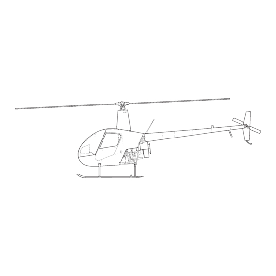
Page 27: External Dimensions
1.008 External Dimensions FIGURE 1-1 EXTERNAL DIMENSIONS Page 1.5 Chapter 1 General OCT 2014... - Page 28 1.008 External Dimensions (continued) FIGURE 1-1A EXTERNAL DIMENSIONS Page 1.6 Chapter 1 General OCT 2014...
- Page 29 1.008 External Dimensions (continued) FIGURE 1-1B EXTERNAL DIMENSIONS Page 1.7 Chapter 1 General OCT 2014...
-
Page 30: Version Description
Refer to R22 Illustrated Parts Catalog (IPC) for specific part number differences between versions. R22 Standard: Approved March 16, 1979. Serial numbers 0002 thru 0199, except 0175. Lycoming O-320-A2B or Lycoming O-320-A2C engine normally rated at 150 horsepower and derated to 124 horsepower. 80/87 minimum grade aviation gasoline. - Page 31 Auxiliary fuel system optional. R22 Mariner II: Approved January 31, 1996. Serial numbers 2571 thru 3414 eligible (suffix “M” added to ship serial number). Similar to Beta II configuration except includes utility floats and additional corrosion protection. Battery in nose when floats installed.
- Page 32 TABLE 1 SCHEDULED MAINTENANCE AND INSPECTIONS Perform maintenance & inspection per Lycoming Operator’s Manual.* • • • • • Perform Lycoming SI 1129B • • Methods of Checking DC Alternator and Generator Belt Tension. Perform Lycoming SI 1191A • Cylinder Compression. Perform Lycoming SI 1080C •...
-
Page 33: Helicopter Servicing
Most bearings are sealed or self-lubricated and do not require periodic lubrication. Bearings with scheduled lubrication intervals are listed in Table 1. Engine lubrication requirements are contained in the R22 Pilot’s Operating Handbook, the appropriate model Lycoming Operator’s Manual, and Lycoming Service Instruction No. 1014 (current revision). Fill main and tail gearboxes to center of sight glasses with A257-2 oil. -
Page 34: Chip Detector Cleaning
1.115 Chip Detector Cleaning WARNING Refer to appropriate Material Safety Data Sheet (MSDS) and take necessary safety precautions when working in proximity to hazardous materials. 1. Disconnect chip detector wiring from airframe harness at connectors. For tail gearbox chip detector, place suitable drain container below gearbox. Remove chip detector from housing or gearbox. -
Page 35: Main Rotor Gearbox Drain And Flush
1. Run-up helicopter for approximately five minutes at 60-70% RPM per R22 Pilot’s Operating Handbook (POH) Section 4 as required to warm oil and expedite draining. 2. Disconnect chip detector wiring from airframe harness at connectors. Remove chip detector from housing. -
Page 36: Tail Rotor Gearbox Drain And Flush
1. Run-up helicopter for approximately five minutes at 60-70% RPM per R22 Pilot’s Operating Handbook (POH) Section 4 as required to warm oil and expedite draining. 2. Disconnect chip detector wiring from airframe harness at connectors. Place a suitable drain container below tail rotor gearbox and remove chip detector. -
Page 37: A184 Upper Bearing Lubrication
4. Slide tip of steel probe under seal inner lip and return deflected portion of lip to original position. Do not damage seal. 5. Run-up helicopter for approximately two minutes 104% RPM per R22 Pilot’s Operating Handbook (POH) Section 4. Shut down, inspect bearing, and clean off any escaped grease. - Page 38 1.150 Defueling WARNING Refer to appropriate Material Safety Data Sheet (MSDS) and take necessary safety precautions when working in proximity to hazardous materials. WARNING Always fuel or defuel helicopter in a well-vented area. smoking within 100 feet of aircraft during fueling. 1.
- Page 39 3. Preserve engine for storage per Lycoming Service Letter no. L180 (current revision). 4. Fill main and tail gearboxes to center of sight glass with A257-2 oil. 5. Fuel helicopter per R22 Pilot’s Operating Handbook (POH) Section 8. NOTE Fuel lubricates bladder inner liner and keeps it from drying out or cracking.
- Page 40 FIGURE 1-3 GROUND HANDLING WHEELS (LEFT SKID SHOWN) Page 1.15C Chapter 1 General OCT 2014...
- Page 41 1.200 Handling, Jacking, Hoisting, Leveling, and Weighing 1.210 Ground Handling 1.211 Ground Handling Wheels Refer to R22 Illustrated Parts Catalog (IPC) Figure 9-1. NOTE R22 ground handling wheels are installed outboard of landing gear skid tubes. A063-1 wheel assemblies are interchangeable (may be installed in right or left skid support).
- Page 42 1.212 Ground Handling Wheels - Float Landing Gear INSTALLATION 1. Pull tail down. Insert forward blocks at their lower height under both skids at forward marks. 2. Push tail up. Insert rear blocks at their lower height under both skids at rear marks.
-
Page 51: Weighing And Cg Calculation
1.231 Preparing Helicopter for Weighing 1. Defuel helicopter per § 1.150. 2. Service engine oil per R22 Pilot’s Operating Handbook (POH) Section 8. Fill main and tail gearboxes to center of sight glass with A257-2 oil. 3. Clean aircraft per POH Section 8. Verify helicopter is completely dry. - Page 52 (CG from step 5) x (Empty weight from step 8) + 23011 (Empty weight from step 8) + 249 10. If CG from step 9 is aft of aft limit (refer to R22 Pilot’s Operating Handbook [POH] Section 2 for model-specific data), determine required nose ballast: [CG from step 5 –...
- Page 53 1.232 Weighing Procedure and Calculations (continued) 11. Adjust weight and balance to correct for drained unusable fuel and ballast: Longitudinal CG Item Weight (lb) (arm, inches) Moment (in.-lb) Multiply empty weight from step 8 by CG from step 5 Nose ballast: 37.5 10.2*, 6.0**, Unusable fuel (add):...
- Page 54 FIGURE 1-9 NOSE BALLAST (View inside lower console assembly with upper console hinged aft) Page 1.28 Chapter 1 General OCT 2014...
-
Page 55: Ballast Installation
5. Remove foam, hinge upper console assembly forward, and install screws. Verify security. 6. Reweigh and/or calculate basic empty weight and CG per § 1.232. 7. Revise Weight and Balance Record in R22 Pilot's Operating Handbook (POH) Section 6 to reflect ballast removal or installation using the following data:... - Page 56 Given Symbols Y = Unknown Y = Torque wrench setting T = 135 in.-lb T = Torque applied to fastener L = 10 in. L = Length of torque wrench A = 1.5 in. A = Length of adapter When using an adapter that lengthens torque wrench effective length, calculate torque wrench setting using the formula below: EXAMPLE T x L...
-
Page 57: Fastener Torque Requirements
A secondary locking mechanism is required on all critical fasteners. B330 stamped nuts (palnuts) serve as the secondary locking mechanism in most areas on the helicopter, and are torqued per § 1.320. Palnuts must be replaced when removed. The R22 Illustrated Parts Catalog (IPC) lists secondary locking mechanisms for specific fasteners. -
Page 58: Torque Seal
1.310 Torque Requirements (continued) WARNING Unless otherwise specified, two threads minimum must be exposed beyond nut on any installation to insure proper locking of fastener. Four threads maximum may be exposed. More than four threads exposed may allow nut to seat against bolt shank, resulting in insufficient joint clamping. -
Page 59: Standard Torques
1.320 Standard Torques NOTE 1. Values in inch-pounds unless otherwise specified. 2. Values include nut self-locking torque. 3. Increase values 10% if torqued at bolt head. 4. Wet indicates threads lubricated with A257-9 anti-seize. 5. For elbow and tee fittings which require alignment, torque to indicated value, then tighten to desired position. -
Page 60: Special Torques
1.330 Special Torques These torques are non-standard and supersede those in § 1.320. NOTE 1. Values in inch-pounds unless otherwise specified. 2. Values include nut self-locking torque. 3. Increase values 10% if torqued at bolt head. 4. Wet indicates threads lubricated with A257-9 anti-seize. 5. -
Page 61: Fuselage
1.330 Special Torques (continued) AREA (QUANTITY) FASTENER TORQUE (4) MS27039DD1-26 screws, air bypass door 22-25 in.-lb (1) MS21042L4 nut, gascolator mounting plug 70 in.-lb FUEL SYSTEM (continued) (1) 0353-6-6 bulkhead union and nut 285 in.-lb Primer system line assembly nuts, flared end fittings 20-30 in.-lb (1) B277-052 clamp, lower rib 50 in.-lb... - Page 62 1.330 Special Torques (continued) AREA (QUANTITY) FASTENER TORQUE (4) AN818-8 nuts, oil cooler line (stainless-steel lines) 40 ft-lb (4) AN818-8 nuts, oil cooler line (aluminum lines) 230–260 in.-lb (1) AN894D4-3 bushing, manifold pressure line, 135–150 in.-lb at firewall (1) 3080-00038 cylinder head temperature probe 70–80 in.-lb (1) bolt, alternator belt tension 204 in.-lb...
- Page 63 1.330 Special Torques (continued) AREA (QUANTITY) FASTENER TORQUE (1) B549-1 retainer, input seal 70 ft-lb wet (3) MS20074-04-06 bolts, gearbox-to-tailcone mounting 100 in.-lb (8) MS20074-04-06 bolts on A021 gearbox 60 in.-lb (12) MS20074-04-06 bolts on B021 gearbox 100 in.-lb (1) MS21042L4 nut, A031 pitch control housing stud 90 in.-lb (1) MS21042L4 nut, A119-1 bumper retainer 120 in.-lb...
-
Page 64: Approved Materials
1.400 Approved Materials The following items are available from the noted manufacturer(s) or their distributor(s). Check with appropriate regulatory authority(s) for allowable usage of materials. WARNING Refer to appropriate Material Safety Data Sheet (MSDS) and take necessary safety precautions when working in proximity to hazardous materials. -
Page 65: Fillers And Putty
1.420 Solvents and Cleaners (continued) PRODUCT MANUFACTURER/SUPPLIER APPLICATION #112 Ammoniated or L&R Mfg. Co. Ultrasonic cleaning, avionics #222 Nonammoniated cleaning Kearny, NJ components only. & rinse solution * May be used on acrylic plastic. ** Mix 5%-20% by volume; titration not required. 1.430 Fillers and Putty PRODUCT MANUFACTURER/SUPPLIER... -
Page 66: Paints
FIGURE 1-12 PAINT CODES (Refer to Chapter 9 for rotor blade paint dimensions. Exterior surface codes are D & F unless otherwise specified.) 1.455 Powder Coat (continued) PRODUCT MANUFACTURER 49/72460 Smooth Glossy Tiger Drylac USA Gray RAL 7043 Cucamonga, CA Polyester Topcoat Powder* 49/22460 Smooth Glossy “... - Page 67 1.460 Paints Refer to Figures 1-12 and 1-13 for paint code application. Paint codes for specific helicopter serial numbers are listed on the inside cover of factory-supplied maintenance record (logbook). NOTE Use fisheye eliminator, accelerator, or other additives per manufacturer's recommendations. CODE MATERIAL MANUFACTURER...
- Page 68 FIGURE 1-13 PAINT CODES Page 1.42 Chapter 1 General OCT 2014...
-
Page 69: Lubricants
1.460 Paints (continued) For limited touch-up of interior and landing gear only: CODE MATERIAL MANUFACTURER Krylon 1613 (shelf life 2 years) Krylon Div. of Borden Semi-Flat Black (aerosol can) Columbus, OH NYBC 14 (shelf life 2 years) New York Bronze Powder Co. Semi-Flat Black Scranton, PA Cardinal A-2000-05... -
Page 70: Adhesives And Sealants
1.470 Lubricants (continued) RHC PART MANUFACTURER’S LUBRICANT TYPE MANUFACTURER PART NO. A257-16 Engine oil Aviation oil 20W-50, Exxon Mobil Corp. SAE J1966 Fairfax, VA A257-17 Substitute A257-19 A257-18 O-ring lubricant Dow Corning Corp. Midland, MI A257-19 Valve lubricant and Dow Corning Corp. sealant compound Midland, MI A257-21... - Page 71 1.480 Adhesives and Sealants (continued) DESCRIPTION COLOR MFR. PART NO. MANUFACTURER PART NO. B270-12 Sealant - electrical potting (2-part) Any color MIL-PRF-8516 except red Type II, Class 2, Category A or B B270-13 Sealant - silicone rubber, Translu- 3145 Dow Corning Corp. noncorrosive (1-part) cent Midland, MI...
- Page 72 1.490 Storage Limits 1. B283 hoses have a shelf storage life of 5 years. Hose service life is “on condition”, with a maximum of 12 years. 2. Elastic cords have a shelf storage life of 5 years. Elastic cord service life is “on condition”, with a maximum of 12 years.
-
Page 77: Introduction
CHAPTER 2 INSPECTION Section Title Page 2.000 Introduction ..........2.1 2.100 General Procedures . - Page 78 CHAPTER 2 INSPECTION (Continued) Section Title Page 2.610 Inspection Procedure ........2.60 2.620 Additional Parts Requiring Replacement on Some R22s .
- Page 79 INSPECTION 2.000 Introduction The R22 helicopter must be inspected periodically to verify it is in airworthy condition. Required inspection intervals are maximum 100 hours time in service or 12 calendar months (annually), whichever occurs first. Fluid leaks, discoloration, dents, scratches, nicks, cracks, galling, chafing, fretting, and corrosion all warrant further investigation.
-
Page 80: Rod Ends And Spherical Bearings
2.122 Rod Ends and Spherical Bearings Refer to Figure 2-1. 1. Maximum axial play: 0.020 inch Maximum radial play: 0.010 inch 2. Looseness between bearing outer race and rod end housing is not permitted. 3. Rod ends not riveted in place must block passage of 0.020 inch diameter wire through witness hole. -
Page 97: Inspection Procedures And Checklist
Fuel Cap(s): Refer to Figure 2-4A. Verify A689-6 fuel cap is revision J or subsequent if bladder tanks are installed. Inspect condition. Verify no deterioration of gasket(s). Verify security when closed. Refer to R22 SB- 107; verify cap decal is legible and properly installed, and alignment marks on cap and tank align when cap is fully closed. - Page 98 FIGURE 2-4B A947-1 FLEX PLATE INSPECTION AND REPAIR LIMITS 2.410 Inspection Procedures and Checklist (continued) 6. Open Cowling Door(s) (6A & 6B) & Remove Aft Cowling (6C) (continued) Tail Rotor Push-Pull Tube and Bellcrank (at forward end of A121-15 push- pull tube): Inspect condition.
- Page 99 2.410 Inspection Procedures and Checklist (continued) 6. Open Cowling Door(s) (6A & 6B) & Remove Aft Cowling (6C) (continued) Main Rotor Gearbox: Inspect condition, especially gearbox mounts, static mast tube-to-gearbox attachment, and mast tube lower casting (if applicable). Inspect Telatemp per § 2.130. Verify proper oil level with no leakage.
- Page 100 2.410 Inspection Procedures and Checklist (continued) 6. Open Cowling Door(s) (6A & 6B) & Remove Aft Cowling (6C) (continued) Upper Sheave: Inspect condition. Verify smoothness of drive belt contact surfaces. Replace any sheave having corrosion, pitting, flaking, roughness, sharp ridges, wear through anodized coating, or blistering of optional metalized coating.
-
Page 101: Rigging
2.410 Inspection Procedures and Checklist (continued) 7. Remove Side Skirts (7A, 7B, 7D, & 7E), Spark Plug Access Covers (7C & 7F), and Battery Box Cover (7G, alternate location under upper console or left seat) (continued) Alternator & Pulley: Inspect condition. Verify steel pulley (use magnet); aluminum pulley is not approved. - Page 102 2.410 Inspection Procedures and Checklist (continued) 7. Remove Side Skirts (7A, 7B, 7D, & 7E), Spark Plug Access Covers (7C & 7F), and Battery Box Cover (7G, alternate location under upper console or left seat) (continued) Oil Lines & Elbows: Inspect condition. Verify clearance and no cracks or abrasions.
- Page 103 If clamp is not installed, verify no more than 0.0049 inch wear into frame tube due to drive belt rubbing. Protective clamp may be installed per Figure 2-4C on any R22 if desired. FIGURE 2-4C UPPER FRAME PROTECTIVE CLAMP INSTALLATION (View looking forward) Page 2.25...
- Page 104 2.410 Inspection Procedures and Checklist (continued) 8. Remove Tailcone Fairing (8) (continued) Actuator Upper Bearing: Inspect condition. Verify no more than 0.060 inch axial play. Verify no fretting between bearing inner race and clutch shaft. Verify bearing inner race has not slipped relative to clutch shaft. Inspect Telatemp per §...
- Page 113 2.410 Inspection Procedures and Checklist (continued) 11. Open Mast Faring (11) (continued) FIGURE 2-8 MEASURING UPPER SWASHPLATE SCISSORS PLAY (Identify scissors bearing type and measure as shown) Page 2.35 Chapter 2 Inspection MAR 2016...
- Page 114 2.410 Inspection Procedures and Checklist (continued) 12. Rotor Hub and Hinge Bolts Hub: Inspect condition. Verify no nicks, scratches, gouges, or corrosion. If main rotor imbalance is suspected, check teeter and coning hinge friction per § 9.124. Verify no brown or black residue (indicates bearing wear). Hinge Bolts: Inspect condition.
-
Page 115: Seat Belt
Visually inspect critical bond areas and verify no separation. Install tip covers, ensuring cover edges are flush with blade profile. A016-4 Main Rotor Blade Bond Inspection: Perform R22 SB-103A or subsequent. Main Rotor Blade Inspection: Inspect skins and doublers for scratches and corrosion per §... - Page 116 Inspect mounts and verify no loose swages or worn bearings. Floats (if installed): Perform relief valve and bulkhead tests per § 2.580 (2) and (3). Verify proper inflation pressure per R22 POH. Inspect condition. Verify security. Float Skid Tubes (if installed): Remove drain plugs at aft end of skid extensions.
- Page 117 2.410 Inspection Procedures and Checklist (continued) 16. Life-limited Parts, Component Overhaul and Retirement, ADs, & SBs Component Retirement: Replace components that have reached maximum service life per § 3.100. Verify components installed correspond with helicopter maintenance record and have sufficient time remaining for projected operations.
- Page 118 Intentionally Blank Page 2.40 Chapter 2 Inspection OCT 2014...
-
Page 145: Special Inspections
Do not use compressed air near main rotor blade drain holes. 2. Refer to R22 Pilot’s Operating Handbook (POH) Section 8. Thoroughly clean, wash, and rinse helicopter, including inner circumference of drive belts. - Page 146 2.810 Volcanic Ash Recommendations (continued) 9. Inspect engine oil condition. Regardless of oil time-in-service if oil smells bad, is opaque (or is not obviously brown), or if particulates are detectable on the dipstick, change engine oil & oil filter, inspect suction screen and old oil filter, and perform Lycoming SI 1191A Cylinder Compression check if not previously accomplished in step 6.
- Page 147 CHAPTER 3 LIFE-LIMITED COMPONENTS Section Title Page 3.000 Life-Limited Components ........3.1 3.001 Introduction .
- Page 148 Intentionally Blank Page 3.ii Chapter 3 Life-Limited Components OCT 2014...
-
Page 149: Life-Limited Components
CHAPTER 3 LIFE-LIMITED COMPONENTS 3.000 Life-Limited Components 3.001 Introduction This section lists fatigue life-limited parts and specified overhaul requirements for the R22 helicopter. 3.002 Time-In-Service Records It is the operator’s responsibility to maintain accurate time-in-service records for the airframe, engine, and life-limited components. R22s are equipped with either an oil- pressure-activated hourmeter which records engine run time or a collective-activated hourmeter which records flight (collective up) time. -
Page 150: Inspection And Overhaul Requirements
3.140 Additional Bearing Replacement Requirements R22 main rotor gearbox assemblies S/N 0002 thru 0232 must be returned to RHC for replacement of original pinion bearings at first 1000 hours time in service. - Page 151 Title 14 of the Code of Federal Regulations. Type Certificate Holder: Robinson Helicopter Company 2901 Airport Drive Torrance, California 90505 I. Model R22 Helicopter (Normal Category), Approved March 16, 1979 Engine Lycoming O-320-A2B or O-320-A2C or O-320-B2C (See NOTES 5 & 6) Fuel...
- Page 152 H10WE Page 2 of 10 I. Model R22 Helicopter (Normal Category), Approved March 16, 1979, (cont'd) Maximum Gross Weight 1300 lbs. No. Seats 2 (See NOTE 1) Minimum Weight 920 lbs. Maximum Baggage 50 pounds of baggage and installed equipment in either baggage compartment, except combined seat load plus baggage and equipment not to exceed 240 pounds.
- Page 153 III. Model R22 BETA Helicopter (Normal Category), Approved August 12, 1985 The R22 BETA Helicopter includes a 131 hp. takeoff rating. A larger oil cooler and associated installation changes were made to permit the 131 hp. takeoff rating with the O-320 engine.
- Page 154 IV. Model R22 MARINER Helicopter (Normal Category), Approved September 12, 1985 The R22 MARINER helicopter includes two inflatable floats, additional corrosion protection, 131 hp. takeoff rating, tailcone with nose-up horizontal stabilizer mounting angle and float stabilizer in place of the tail skid. The helicopter can be used with or without floats.
- Page 155 H10WE Page 5 of 10 IV. Model R22 MARINER Helicopter (Normal Category), Approved September 12, 1985, (cont'd) Rotor Speed Limits Power Off (Rotor Tach) for Power On (Rotor Power On (Rotor O-320-B2C and O-360-J2A Tach) for O-320-B2C Tach) for O-360-J2A...
- Page 156 R22 BETA with O-360-J2A R22 Rotorcraft Flight Manual dated March 16, 1979,with revisions through August 7, 1985 or later. For R22 Rotorcraft Flight Manual with revisions prior to October 13, 2000, Flight Manual Supplement 7 dated January 31, 1996, or later revision, is required (see NOTE 8).
- Page 157 NOTE 3. Retirement time of critical components is contained in the FAA approved "AIRWORTHINESS LIMITATIONS" section of the Robinson R22 Maintenance Manual. The values of retirement or service life and inspection intervals cannot be changed without FAA Engineering approval. NOTE 4.
- Page 158 H10WE Page 8 of 10 NOTE 12. changes to the type design of this helicopter by means of an amended type certificate (TC), supplemental type certificate (STC), or amended STC, requiring instructions for continued airworthiness (ICA’s) must be submitted through the project aircraft certification office (ACO) for review and acceptance by the Fort Worth -Aircraft Evaluation Group (FTW-AEG) Flight Standards District Office (FSDO) prior to the aircraft delivery, or upon issuance of the first standard airworthiness certificate for the affected aircraft, whichever occurs later as prescribed by Title 14 CFR 21.50.
- Page 159 H10WE Page 9 of 10 _______________________________________________________________________________ R22 ALPHA AND BETA FIGURE 2 Page 3.11 Chapter 3 Life-Limited Components OCT 2014...
- Page 160 H10WE Page 10 of 10 WITH FLOATS __________________ WITHOUT FLOATS ___ ___ ___ ___ __________________________________________________________________________________ _________________________________________________________________________________ R22 MARINER FIGURE 3 ..END..Page 3.12 Chapter 3 Life-Limited Components OCT 2014...
-
Page 161: Airworthiness Limitations
Either method may be used, however numerical values for service lives depend on the tracking method used. R22 Fatigue Life-Limited Parts Use the following lives if time is tracked based on engine run time as recorded by an oil-... - Page 162 3.300 Airworthiness Limitations (cont’d) R22 Fatigue Life-Limited Parts (cont’d) Use the following lives if time is tracked based on flight (collective up) time as recorded by a collective-activated hourmeter: Part Number Description Maximum Service Life A016-2 (Retired by AD 2004-19-09) . . Main Rotor Blade ....1964 Hours or 10 years A016-4 .
-
Page 163: Windshield Assembly
CHAPTER 4 AIRFRAME Section Title Page 4.000 Airframe ..........4.1 4.001 Introduction . - Page 164 CHAPTER 4 AIRFRAME (Continued) Section Title Page 4.322 Empennage Installation ........4.23 4.323 Upper Stabilizer Replacement .
- Page 165 4.002 Description The R22 is a two-place, single main rotor, single engine helicopter constructed primarily of metal and equipped with skid-type landing gear. The primary fuselage structure is welded steel tubing and riveted aluminum sheet. The tailcone is a monocoque structure in which aluminum skins carry primary loads.
- Page 166 4.120 Windshield Assembly The windshield is made of transparent plexiglass set in a weather-tight silicone sealer and is screwed to the cabin structure. 4.121 Windshield Removal a. Remove door and hinges. NOTE To prevent scratches in the windshield, a protective cover should be taped to the inside and outside of the windshield prior to removal.
-
Page 191: Landing Gear Removal
CHAPTER 5 LANDING GEAR Section Title Page 5.000 Landing Gear ..........5.1 5.001 Introduction . - Page 192 Intentionally Blank Page 5.ii Chapter 5 Landing Gear OCT 2014...
-
Page 193: Hard Landing
(becomes permanently bent) to absorb the impact. Slight crosstube yielding is acceptable. However, yielding which allows the tail skid to be within 34 inches (24 inches for R22 Standard or HP) of the ground when the helicopter is sitting empty on level pavement requires crosstube replacement. - Page 194 FIGURE 5-1 JACKING Page 5.2 Chapter 5 Landing Gear OCT 2014...
-
Page 207: Powerplant And Related Systems
CHAPTER 6 POWERPLANT Section Title Page 6.000 Powerplant And Related Systems ....... . 6.1 6.001 Introduction . -
Page 208: Powerplant
CHAPTER 6 POWERPLANT (Continued) Section Title Page 6.730 Throttle Push-Pull Tube Assembly ......6.26 6.731 Throttle Push-Pull Tube Assembly Removal . - Page 209 A2B or O-320-A2C engines are installed in standard model R22s and are normally rated at 150 horsepower. O-320-B2C engines are installed in R22 HP, R22 Alpha, and R22 Beta models and are normally rated at 160 horsepower. Beta II/Mariner II helicopters have an O-360-J2A engine capable of 180 horsepower, derated by Lycoming to 145 horsepower.
-
Page 210: Side Skirts
6.100 Powerplant NOTE Refer to engine and engine component manufacturer mainte- nance publications for product specific inspection, repair, and maintenance procedures. 6.110 Engine Removal NOTE If engine is to be removed to facilitate a lower frame replacement, engine mount change, or firewall repair, fanwheel can remain installed. -
Page 233: Air Filter Cleaning
6.435 Air Filter Cleaning NOTE Replace B771-1 air filters after 5 years or 600 flight hours, whichever occurs first. 1. Remove B771-1 air filter from airbox. Visually inspect filter and verify no obvious damage. Inspect filter’s pleated media for cleanliness. If the media contains only dust, clean media using compressed air or water. -
Page 234: Carburetor Heat Scoop Removal
6.450 Carburetor Heat Scoop Removal 1. Disconnect hose from carburetor heat scoop. 2. 0-320 engine: Remove six screws securing curved sheet metal and remove sheet. 0-360 engine: Remove two B277 clamps securing scoop assembly to exhaust manifold and remove scoop. 3. -
Page 243: A006-5/A908-4 Yoke Removal And Installation
CHAPTER 7 DRIVE TRAIN Section Title Page 7.000 Drive Train ..........7.1 7.001 Introduction . - Page 244 CHAPTER 7 DRIVE TRAIN (Continued) Section Title Page 7.310 Tail Rotor Drive Shaft Removal ....... 7.34 7.320 Tail Rotor Drive Shaft Installation .
-
Page 245: Mast Fairing
CHAPTER 7 DRIVE TRAIN 7.000 Drive Train 7.001 Introduction This section contains procedures for removal, installation, replacement, and maintenance of drive train components. 7.002 Description (See Figure 7-1) A steel-coated multiple-grooved aluminum pulley, known as the lower sheave, is bolted directly to the crankshaft. - Page 246 FIGURE 7-1 DRIVE TRAIN Page 7.2 Chapter 7 Drive Train OCT 2014...
-
Page 261: Clutch Assembly Seal Replacement
7.213 Clutch Assembly Seal Replacement 1. Remove clutch assembly per § 7.210. 2. If replacing aft seal, remove A184-3 bearing assembly from clutch shaft per § 7.211. Remove loose paint and clean shaft. NOTE Orient clutch assembly vertically with leaking seal up. 3. -
Page 262: Clutch Assembly Lubricant Inspection And Servicing
Fluid may be dark, and may sparkle with very fine metallic debris; this is normal. If metallic debris is trapped in the filter/strainer, remove clutch assembly and return it to RHC, or an R22 Service Center authorized to overhaul clutch assemblies, for disassembly and inspection. -
Page 281: V-Belts
FIGURE 7-8A V-BELT GUIDE 7.282 V-Belt Installation (continued) CAUTION Position guide to 0.18 inch clearance with clutch engaged. Guide to be flushed with front face of sheave. Maintain 0.18 inch clearance between P/P tube and guide attach bolts. NOTE A020-2 upper frame S/N 0501 and subsequent have guide bracket welded to frame. - Page 282 7.290 A007-3 & -5 Fanshaft and Bearing Assembly, Starter Ring Gear Support, Lower Sheave and Alternator Belt Replacement 7.291 Removal a. Remove fanwheel and fiberglass scroll per § 6.210. NOTE Fanwheel and fiberglass scroll may be removed without splitting scroll. b.
-
Page 317: Cyclic Controls
CHAPTER 8 FLIGHT CONTROLS Section Title Page 8.000 Flight Controls ..........8.1 8.001 Introduction . -
Page 318: Swashplate
CHAPTER 8 FLIGHT CONTROLS (Continued) Section Title Page 8.225 Collective Friction Adjustment ......8.34 8.230 RPM Governor System . - Page 319 CHAPTER 8 FLIGHT CONTROLS (Continued) Section Title Page 8.542 Bellcrank Installation ........8.57 8.550 A120-3 Aft Bellcrank .
- Page 320 Intentionally Blank Page 8.iv Chapter 8 Flight Controls OCT 2014...
-
Page 321: Collective Control
CHAPTER 8 FLIGHT CONTROLS 8.000 Flight Controls 8.001 Introduction This section covers removal and installation procedures for cyclic controls, collective controls, tail rotor controls and their related components. WARNING Assembly of flight controls is critical and requires inspection by a qualified person. If a second person is not available, the installer must take a 5-minute break prior to inspecting flight control connections he has assembled. -
Page 322: Main Rotor
FIGURE 8-1 MAIN ROTOR FLIGHT CONTROLS Page 8.2 Chapter 8 Flight Controls OCT 2014... - Page 389 CHAPTER 9 ROTOR SYSTEMS Section Title Page 9.000 Rotor Systems ..........9.1 9.100 Main Rotor .
- Page 390 Intentionally Blank Page 9.ii Chapter 9 Rotor Systems OCT 2014...
- Page 391 The teeter hinge bearings are elastomeric. The tail rotor blades are constructed with aluminum skins and forged aluminum root fittings. 9.100 Main Rotor Refer to R22 Illustrated Parts Catalog (IPC) Chapter 62. 9.110 Main Rotor Blades WARNING Due to potentially destructive results, use of blade tape (anti- erosion tape) is prohibited.
- Page 392 FIGURE 9-1B MEASURING BOLT STRETCH (SHOWN ON TEETER BOLT, BLADES REMOVED) Page 9.2 Chapter 9 Rotor Systems OCT 2014...
-
Page 393: Rotor Systems
9.111 Main Rotor Blade Removal (continued) 1. Mark one main rotor blade and its corresponding hub location, pitch link, and retaining nut & bolt with “X” using a marker or grease pencil. Mark opposite blade and its hub location, pitch link, and retaining nut & bolt with “O”. 2. -
Page 394: Main Rotor Blade Installation
9.112 Main Rotor Blade Installation 1. Identify hub and spindle part numbers and ensure correct corresponding installation hardware. 2. Check teeter hinge friction and adjust as required per § 9.124. 3. If coning hinge axial gap recorded during blade removal was beyond tolerance, or if corresponding hub bearing(s) or spindle was replaced, perform coning hinge journal and shim calculation per §... -
Page 395: Boot Removal
9.112 Main Rotor Blade Installation (continued) 10. a. A154-1 hub with NAS630-80 (or MS21250-10080) coning hinge bolts: i. If bolt elongation is 0.015–0.017 inch, remove tool and install a new cotter pin wet with epoxy primer. ii. If bolt elongation is not 0.015–0.017 inch, remove old nut and old bolt and install a new bolt and a new nut. -
Page 396: Filling Pitch Bearing Housing
FIGURE 9-1C FILLING PITCH BEARING HOUSING Page 9.6 Chapter 9 Rotor Systems MAR 2016... -
Page 397: Drilling Main Rotor Hub Bolts
9.115 Filling Pitch Bearing Housing NOTE MT147-1 Main rotor blade spindle air bleed tool includes supply container, hose assemblies, and bleed fittings. WARNING Refer to appropriate Material Safety Data Sheet (MSDS) and take necessary safety precautions when working in proximity to hazardous materials. -
Page 398: Main Rotor Hub
9.120 Main Rotor Hub 9.121 Main Rotor Hub Removal 1. Remove main rotor blades per § 9.111. 2. Refer to Figure 9-2A. Mark rotor hub using a grease pencil, tape, or soft marker as follows: a. Indicate nut side of teeter bolt. b. - Page 399 9.122 Main Rotor Hub Installation (continued) 6. Using wrenches with at least 150 ft-lb torque capacity, tighten nut until drilled holes in nut and bolt align. Install MT122 tool and measure bolt elongation: a. If bolt elongation is 0.015–0.017 inch, remove tool and verify correct teeter hinge friction per §...
- Page 400 FIGURE 9-2A TEETER HINGE (HUB INSTALLATION) FIGURE 9-2B B370-1 HUB CONING HINGE (BLADE INSTALLATION; VIEW LOOKING DOWN) Page 9.10 Chapter 9 Rotor Systems MAR 2016...
- Page 401 FIGURE 9-2C A154-1 HUB CONING HINGE (BLADE INSTALLATION; VIEW LOOKING DOWN) A106 Journal Lengths Part No. Length Location A106-1 1.000 in. Coning hinge, no shims (A154-1 Hub) A106-2 0.995 in. Coning hinge, no shims (A154-1 Hub) A106-3 0.990 in. Coning hinge, no shims (A154-1 Hub) A106-4 1.300 in.
- Page 402 9.123 Main Rotor Hub Journal and Shim Calculations Refer to Table 9-1 and Figures 9-2A, 9-2B, and 9-2C. A. Teeter Hinge Calculation 1. Measure main rotor hub width across the teeter hinge bearing faces: 2. Subtract measured width of A251 driveshaft at teeter hinge bolt hole: – Calculated empty space: = 3.
-
Page 403: Main Rotor Hub Journal And Shim Calculations
9.123 Main Rotor Hub Journal and Shim Calculations (continued) B. Coning Hinge Calculation B370-1 Hub: 1. Measure main rotor hub width across the coning hinge bearing faces: 2. Subtract measured width of blade spindle at teeter hinge bolt hole: – Calculated empty space: = 3. - Page 404 FIGURE 9-3A MEASURING CONING HINGE AXIAL GAP FIGURE 9-3B MEASURING TEETER HINGE FRICTION Page 9.12 Chapter 9 Rotor Systems MAR 2016...
- Page 405 9.123 Main Rotor Hub Journal and Shim Calculations (continued) B. Coning Hinge Calculation (continued) A154-1 Hub: 1. Measure main rotor hub width across the coning hinge bearing faces: 2. Subtract measured width of blade spindle at coning hinge bolt hole: – Calculated empty space: = CAUTION Initial coning hinge hardware stack-up must be adjusted to...
-
Page 406: Shifting The Main Rotor Hub
9.124 Adjusting Hinge Friction (continued) B. Coning Hinge Friction Adjustment 1. Refer to Figure 9-2B and Table 9-1. Remove cotter pin, nut, thrust washer, and cone blade to remove nut-side journal. a. B370-1 Hub: Adjust coning hinge friction by changing trailing-edge shim stack thickness in small increments;... -
Page 407: Main Rotor Hub Bearing Replacement
FIGURE 9-4 MAIN ROTOR HUB BEARING REPLACEMENT 9.126 Main Rotor Hub Bearing Replacement 1. Remove main rotor hub per § 9.121. 2. Refer to Figure 9-4. Verify tooling surfaces are smooth to avoid damaging hub and bearings. Press A648-1 and/or A648-3 bearing(s) from hub using MT329-1 plug assembly (Rev H or subsequent) with MT329-10 tube. - Page 408 FIGURE 9-5A MEASURING MAIN ROTOR BLADE DAMAGE FIGURE 9-5B SCRATCH LIMITS Page 9.16 Chapter 9 Rotor Systems MAR 2016...
-
Page 409: Inspection Of Main Rotor Blades
9.130 Inspection of Main Rotor Blades NOTE Main rotor blades are 14 CFR § 27.602 critical parts. Notify RHC Technical Support when voids exceeding the limits specified in the instructions below are found, providing blade serial number, helicopter serial number, time in service for the rotor blade, and location and size of the voids that exceed the limits. - Page 410 FIGURE 9-6 DENTS AND LOCAL DEFORMATIONS Page 9.18 Chapter 9 Rotor Systems OCT 2014...
-
Page 411: Dents And Local Deformations
9.132 Dents and Local Deformations CAUTION Tap-test dented areas in honeycomb using an AN970-4 washer or 1965-or-later U.S. quarter dollar coin in good condition. If any voids are found associated with dents, contact RHC Technical Support. CAUTION Do not repair any dent that has a sharp cut or break in the skin;... - Page 412 FIGURE 9-7 ROOT FITTING BLEND LIMITS 9.132 Dents and Local Deformations (continued) 1. e. Spar: Refer to step 2. Blend damaged areas by hand with a minimum 1.0 inch blend radius. Blending is not allowed within 0.010 inch of spar groove leading edge.
-
Page 413: Root Fitting Damage
9.133 Root Fitting Damage 1. Refer to Figure 9-7. Damage may not exceed the following limits: A016-6 Blades: Refer to step 2. Blend damaged areas by hand with a minimum 0.030 inch blend radius. a. 0.002 inch maximum depth blending on flange inboard face. b. - Page 414 FIGURE 9-8 BOND AREAS Page 9.22 Chapter 9 Rotor Systems OCT 2014...
-
Page 415: Voids
9.134 Voids CAUTION Tap-test voids and debonds in blades using an AN970-4 washer or 1965 or later U.S. quarter dollar coin in good condition. CAUTION Voids or debonds in doublers are not field repairable. If voids or debonds are detected in doublers which exceed limits, contact RHC Technical Support. - Page 416 5.0 square inches, 1.10 inches chordwise & 6.0 spanwise maximum void. b. 0.10 square inch maximum void extending into a critical bond area. c. 2.0 inches maximum void from outboard tips (refer to R22 SL-55). 2. Voids in honeycomb bond joints inboard of RS 106.0 may not exceed 8.00 square inches, 1.00 inches chordwise, &...
-
Page 417: Repair Of Main Rotor Blades
9.140 Repair of Main Rotor Blades Refer to § 1.400 for approved materials. CAUTION Do NOT use power tools or chemical paint strippers to repair main rotor blades. 1. Measure damage per § 9.130. 2. Remove damage at trailing edges, trim tab edges, tip cap, and/or tip corner by trimming per §... - Page 418 FIGURE 9-9A TRIM LIMITS Page 9.26 Chapter 9 Rotor Systems OCT 2014...
- Page 419 FIGURE 9-9B FILING SKIN EDGES SQUARE 9.141 Trimming Refer to Figures 9-9A & 9-9B. Trimming may be performed on the trailing edge of main rotor blade skins and trim tab edges within limits shown. (Alternately, a trailing edge nick or notch may be blended out 1.0 inch minimum spanwise, each side of nick or notch within limits shown.) Trimming is not permitted on spar or doublers.
- Page 420 FIGURE 9-10 MAIN ROTOR BLADE PAINT SCHEME (A016-6 BLADE SHOWN) 9.142 Painting (continued) 6. Refer to Figures 9-10. Apply dark gray (root), flat black, white, and/or yellow polyurethane enamel, as required, to primed area in accordance with paint manufacturer’s recommendations. NOTE Allow Imron paint to cure at least 72 hours before flying in erosive conditions (such as drizzle, rain, or dust).
- Page 421 9.200 Tail Rotor 9.210 Tail Rotor Assembly Removal 1. Mark or tag each pitch link and corresponding blade for reinstallation. Remove hardware securing pitch links to tail rotor blades, noting hardware removed. NOTE Tail rotor pitch link-to-blade attach bolts may be different lengths and/or have different washers installed under nut for balancing.
- Page 422 FIGURE 9-11 TAIL ROTOR ASSEMBLY INSTALLATION (A008-4 ASSEMBLY SHOWN) Page 9.26D Chapter 9 Rotor Systems OCT 2014...
-
Page 437: Collective Travel Rigging
CHAPTER 10 RIGGING, TRACK AND BALANCE Section Title Page 10.000 Rigging, Track and Balance ........10.1 10.001 Introduction . - Page 438 Intentionally Blank Page 10.ii Chapter 10 Rigging, Track and Balance OCT 2014...
-
Page 439: Tail Rotor Flight Controls
10.002 Rod End Adjustment Procedures For Rigging The following procedure is a standard for the adjustment of rod ends on the R22 helicopter. 1. Loosen the palnut and jamnut on the rod end. 2. Screw the rod end in or out of the push-pull tube or pitch link as required to obtain the proper rigging adjustment. -
Page 440: Jackshaft
10.100 Rigging 10.110 Main Rotor Flight Controls 10.111 Cyclic Controls The cyclic control travel is non-adjustable and is controlled by A211-1 stop plate attached to the cyclic box assembly. NOTE If the A121-1 push-pull tube length has been changed or the length of the A205 fork was changed, they must be readjusted to the dimensions shown in Figure 8-3. - Page 473 Intentionally Blank Page 10.31 Chapter 10 Rigging, Track and Balance OCT 2014...
- Page 474 FIGURE 10-12 MAIN ROTOR BLADE TRIM TAB ADJUSTMENT Page 10.32 Chapter 10 Rigging, Track and Balance OCT 2014...
- Page 475 CAUTION Do not use other helicopter manufacturers' trim tab bending tools. Use of these tools will damage Robinson blades. CAUTION MT352-1 gage must contact trim tab trailing edge. If gage does not contact tab trailing edge, tab is bent beyond limit.
- Page 476 Intentionally Blank Page 10.32B Chapter 10 Rigging, Track and Balance OCT 2014...
-
Page 485: Heating And Ventilation
CHAPTER 11 HEATING AND VENTILATION Section Title Page 11.000 Heating and Ventilation ........11.1 11.001 Introduction . - Page 486 Intentionally Blank Page 11.ii Chapter 11 Heating and Ventilation OCT 2014...
- Page 487 CHAPTER 11 HEATING AND VENTILATION 11.000 Heating and Ventilation 11.001 Introduction This section contains the procedures necessary for removal, installation and replacement of the heater and ventilation systems. 11.002 Description The cabin heater system consists of an electric blower on left side of the engine compartment, a heat shroud over the muffler, a control valve on the firewall inside the pilot’s baggage compartment, and the interconnecting ducts between components.
-
Page 488: Cabin Heater Installation
11.120 Cabin Heater Installation a. If not already drilled, drill a 2 O.D. inch hole in bottom of right baggage compartment as follows: Drill a #40 hole, 5.30 inches to the right of the keel panel and 1.75 inches forward of the aft firewall. Enlarge hole to 2 O.D. inch diameter using fly cutter. b. - Page 493 CHAPTER 12 FUEL SYSTEM Section Title Page 12.000 Description ..........12.1 12.100 Fuel Tanks .
- Page 494 Intentionally Blank Page 12.ii Chapter 12 Fuel System OCT 2014...
- Page 495 CHAPTER 12 FUEL SYSTEM 12.000 Description Fuel system maintenance is specific to either bladder or all-aluminum tank installations (production aircraft have flexible bladders in aluminum enclosures while earlier aircraft use all-aluminum tanks). Mechanics are advised to identify fuel tank installation type, and to follow the appropriate maintenance procedures.
- Page 496 FIGURE 12-1 FUEL SYSTEM (BLADDER TANK INSTALLATION SHOWN) Page 12.2 Chapter 12 Fuel System OCT 2014...
-
Page 497: Fuel Tanks
12.100 Fuel Tanks CAUTION Flexible hoses kink easily; handle with care. CAUTION Temporarily cap fuel fittings when opened. WARNING Fuel vapors are explosive. Do not use electric tools in vicinity of an opened fuel system. 12.110 Main Tank A. Removal 1. - Page 498 12.110 Main Tank (continued) B. Installation NOTE When positioning main tank in helicopter, verify vertical strip attached to horizontal firewall is between tank’s D249-4 angle (attached to stiffener on bottom of tank) and tank’s exterior skin. NOTE Electrically verify proper function of low-fuel warning switch and fuel quantity sender prior to main tank installation.
- Page 499 12.110 Main Tank (continued) B. Installation (continued) 7. Check fuel quantity indication per § 12.420. Verify no leaks. 8. Inspect fuel cap alignment stripes per R22 Service Bulletin SB-107. Verify proper installation and legibility of D682-44 decals. 9. Install left backrest assembly.
- Page 500 12.110 Main Tank (continued) C. Bladder Replacement (continued) 11. At forward inboard corner, apply A257-9 anti-seize to screw threads and install screws securing bladder to tank. Lubricate new o-rings with A257-6 grease and install o-rings on B254-3 strainer assembly, AN815-4D union, and AN815-6D union.
-
Page 501: Auxiliary Tank
12.120 Auxiliary Tank A. Removal 1. Defuel helicopter per § 1.150. 2. Open right side of mast fairing. Open access doors, disconnect ELT antenna & ground wire at connectors if ELT is installed, and remove tailcone fairing. Remove B423-1 channel assembly and B429 skins. Remove B430 door and skin. 3. - Page 502 9. Install hardware securing pitot-static line clamp to tank channel. 10. Check fuel quantity indication per § 12.420. Verify no leaks. 11. Inspect fuel cap alignment stripes per R22 Service Bulletin SB-107. Verify proper installation and legibility of D682-44 decals.
- Page 503 12.120 Auxiliary Tank (continued) C. Bladder Replacement NOTE During disassembly, progressively tape bladder openings to protect interior from foreign object contamination. During assembly, progressively remove protective tape. CAUTION B028-2 bladder assembly temperature should be above 65°F before removing, installing, or flexing bladder. 1.
- Page 504 FIGURE 12-2 FUEL VENTS Page 12.10 Chapter 12 Fuel System OCT 2014...
-
Page 505: Fuel Vents
12.200 Fuel Vents 12.210 (Vent Line) Rollover Valve Assemblies R22 rollover valves contain one brass ball. In normal conditions, air flows around the vent ball from the bladder expansion spaces. In the event of inadvertent over-filling or in-flight fuel sloshing, the ball will float and seal the vent. If the aircraft is inverted, the ball seals the vent to minimize fuel spillage. - Page 506 D252-3 FUEL QUANTITY SENDER D252-4 FUEL QUANTITY SENDER Main Tank (Bladder Tank) Aux Tank (Bladder Tank) A550-1 FUEL QUANTITY SENDER B122-1 FUEL QUANTITY SENDER Main Tank (All-Aluminum Tank) Aux Tank (All-Aluminum Tank) FIGURE 12-3 FUEL QUANTITY SENDER CHECK Page 12.12 Chapter 12 Fuel System OCT 2014...
-
Page 507: Fuel Quantity
3. Push A729 tube onto valve. Wrap tube with two turns 0.032-inch diameter lockwire and safety tube to valve, as required. 4. Fuel helicopter per R22 Pilot’s Operating Handbook Section 2 and inspect fuel system for leaks. Install engine right cowling, if removed. -
Page 508: Fuel Quantity Indication
1. Defuel helicopter per § 1.150. Turn fuel shut-off valve off. 2. Fuel main tank with exactly 6.2 gallons (bladder tanks) or 5.0 gallons (all-aluminum tanks, aux tank only) of fuel per R22 Pilot’s Operating Handbook Section 2. Wait five minutes for fuel levels to equalize. Inspect for leaks. -
Page 509: Low-Fuel Switch Assembly
6. Perform operation check per Part C. C. Operation Check 1. Turn battery switch on. Fuel helicopter per R22 Pilot’s Operating Handbook Section 2 as required and inspect fuel system for leaks. 2. With a clean wooden dowel, gently depress low-fuel switch assembly float and verify low fuel warning light illuminates after approximately 1 second delay. -
Page 510: Gascolator Assembly
12.500 Gascolator Assembly A. Cleaning Sediment Bowl 1. Turn battery switch off. Turn fuel shut-off valve off. Remove left side skirts. Electrically ground helicopter. Drain fuel into an approved, electrically-grounded container using A666-1 gascolator assembly drain valve. 2. Cut & discard safety wire securing gascolator collar to outlet fitting. Unscrew collar, and remove collar, ring, and sediment bowl. -
Page 511: Minimum Fuel Flow Check
Remove right side skirts. Verify fuel tank cap(s) are installed. 2. Fuel main tank with exactly 3.0 gallons (bladder tanks) or 1.7 gallons (all-aluminum tanks) fuel per R22 Pilot's Operating Handbook Section 2. 3. Disconnect B283 hose assembly from carburetor, turn battery switch and fuel shut-off valve on, and defuel helicopter into an approved, electrically-grounded container until low fuel light illuminates. - Page 512 Intentionally Blank Page 12.18 Chapter 12 Fuel System OCT 2014...
- Page 513 CHAPTER 13 INSTRUMENTS Section Title Page 13.000 Description ..........13.1 13.100 Pitot-Static System .
- Page 514 Intentionally Blank Page 13.ii Chapter 13 Instruments OCT 2014...
- Page 515 CHAPTER 13 INSTRUMENTS 13.000 Description Standard primary instruments include an airspeed indicator, engine and rotor dual tachometer, altimeter, manifold pressure gage, and magnetic compass. Engine gages include an ammeter, oil pressure, oil temperature, cylinder head temperature, and fuel quantity for main and aux (if installed) tanks.
- Page 516 FIGURE 13-1 PITOT-STATIC SYSTEM Page 13.2 Chapter 13 Instruments OCT 2014...
-
Page 517: Pitot-Static System
13.100 Pitot-Static System CAUTION Do not apply suction to pitot system or pressure to static system. A. Pitot System Leak Test 1. Open mast fairing. 2. Refer to Figure 13-1. Seal drain hole in elbow aft of pitot tube with pressure-sensitive tape. -
Page 518: Primary Instruments
1. Remove screws securing instrument face panel to upper console and carefully pull panel aft. 2. Run-up helicopter per R22 Pilot's Operating Handbook (POH) Section 6 at 104% engine tachometer indication. 3. Turn adjustment screw on back of tachometer (apply 1/8 turns) clockwise to increase and counterclockwise to decrease rotor tachometer indication. -
Page 519: Manifold Pressure Gage
13.250 Manifold Pressure Gage The manifold pressure gage provides an indicator of absolute air pressure in the engine intake manifold. The red line on the gage indicates the maximum manifold pressure that the rotorcraft is type certificated for at 104% rotor RPM. The manifold pressure gage should indicate within 0.3 inches Hg of ambient barometric pressure when engine is not running. -
Page 520: Fuel Quantity Gages
13.350 Fuel Quantity Gages The fuel quantity gages indicate the fuel level of main and aux (if installed) fuel tanks and receive signals from variable resistance type senders mounted on the bottom of each tank. 13.360 Carburetor Air Temperature Gage The carburetor air temperature gage is used to determine when carburetor heat is required during possible carburetor icing conditions, such as high humidity. - Page 521 Intentionally Blank Page 13.7 Chapter 13 Instruments OCT 2014...
- Page 522 FIGURE 13-2 SIX-INSTRUMENT CONSOLE WITH ASPEN PFD – TYPICAL FIGURE 13-3 ASPEN PFD PITOT-STATIC SCHEMATIC Page 13.8 Chapter 13 Instruments OCT 2014...
-
Page 523: Optional Equipment
13.500 Optional Equipment 13.510 Aspen PFD Installation Refer to R22 Illustrated Parts Catalog Figures 13-47 and 13-49. A. Description The Aspen PFD (Primary Flight Display) is an LCD unit with displays for attitude, altitude, airspeed, heading, and optional NAV (HSI/CDI). The Aspen PFD is a situational awareness aid, to be used in conjunction with required VFR instruments (altimeter, airspeed indicator, and magnetic compass). - Page 524 13.510 Aspen PFD Installation (continued) E. Antenna Refer to Section 14.700 for antenna locations and R22 Illustrated Parts Catalog (IPC) Chapter 6. NOTE Do not use magnetized tools. Removal 1. Turn battery switch off and pull-out EFIS circuit breaker (7.5 amp) at panel.
-
Page 525: Instrument Markings
3. Secure circuit breaker panel and upper console. Perform ground checks per Part D steps 5 and 6. 13.600 Instrument Markings See R22 Pilot’s Operating Handbook (POH) Section 2 for instrument markings. 13.700 Troubleshooting Vertical Speed Indicator Climb indication with no return to... - Page 526 Intentionally Blank Page 13.12 Chapter 13 Instruments OCT 2014...
-
Page 527: Electrically-Powered Instrument Calibration Values
14.1040 IFR Trainer Avionics Schematics ......14.47 14.1100 R22 Mariner Avionics Schematics ......14.60 14.1200 Avionics for R22 Helicopter S/N 4591, 4650, 4651, 4656 &... - Page 528 Intentionally Blank Page 14.ii Chapter 14 Electrical and Avionics Systems OCT 2014...
- Page 529 The battery is in a fiberglass container normally located on the lower left steel tube frame. An optional location is in the nose under the upper console. Some R22 HP models may have the battery in the left-seat baggage compartment.
- Page 530 14.100 Dual Tachometer Adjustment 1. The early model A792-1 Dual Tachometer is pre-set at the factory and is not adjustable in the field. For repair or adjustment, the unit must be returned to Robinson Helicopter. (No adjustment screw on early models.) 2.
-
Page 541: Electrical Load Analysis
14.500 Electrical Load Analysis To calculate the total electrical load for a specific helicopter, identify all items of equipment installed on the helicopter from the table below and sum the corresponding continuous and intermittent loads. Maximum continuous alternator load is given in the table below: System Voltage Alternator Rating Maximum Continuous Load... - Page 542 14.500 Electrical Load Analysis (continued) CONTINUOUS INTERMITTENT CONTINUOUS INTERMITTENT EQUIPMENT AMPS EACH AMPS EACH TOTAL TOTAL MAIN BUS (continued) AUX POWER PLUG (MAX) 10.00 10.00 10.00 10.00 HEATER BLOWER 7.50 7.50 7.50 7.50 CONTINUOUS INTERMITTENT CONTINUOUS INTERMITTENT EQUIPMENT AMPS EACH AMPS EACH TOTAL TOTAL...
- Page 543 14.500 Electrical Load Analysis (continued) CONTINUOUS INTERMITTENT CONTINUOUS INTERMITTENT EQUIPMENT AMPS EACH AMPS EACH TOTAL TOTAL AVIONICS (continued) KN63 DME 1.21 1.21 1.21 1.21 GARMIN TRANSPONDER 1.10 3.10 1.10 3.10 GARMIN RADIO NAVIGATION 0.41 0.41 0.41 0.41 INDICATOR KING RADIO NAVIGATION 0.08 0.08 0.08...
-
Page 544: Electrical Systems Schematics
FIGURE 14-1 ELECTRICAL SYSTEM SCHEMATIC (S/N 0001 thru 0077) (Impulse coupling ignition; 9/21/79 thru 12/1/80) Page 14.12 Chapter 14 Electrical and Avionics Systems OCT 2014... - Page 573 14.700 Antenna Locations NO. ANTENNA PART NO. NO. ANTENNA PART NO. 1 NAV ....CI 259 6 ADF ....KA44B NAV .
- Page 574 Intentionally Blank Page 14.24 Chapter 14 Electrical and Avionics Systems OCT 2014...
- Page 633 FIGURE 14-39 R22 ELECTRICAL SYSTEM INSTALLATION (A024 Revision BL shown) Page 14.65 OCT 2014 Chapter 14 Electrical and Avionics Systems...
- Page 634 Intentionally Blank Page 14.66 Chapter 14 Electrical and Avionics Systems OCT 2014...
-
Page 635: Avionics For R22 Helicopter S/N 4591, 4650, 4651, 4656 & Subsequent
14.1200 Avionics for R22 Helicopter S/N 4591, 4650, 4651, 4656 & Subsequent 14.1210 A024-9 Electrical System Installation A. Description of New Features 1. Main Switch Panel The main switch panel is located at the top of the avionics stack. Rocker-style switches are utilized for ergonomic comfort for this new location, and for the new console geometry (earlier R22s utilized paddle-style switches). - Page 636 FIGURE 14-40 FULL THROTTLE CAUTION LIGHT RIGGING CHECK Page 14.68 Chapter 14 Electrical and Avionics Systems OCT 2014...
- Page 637 14.1220 A036-9 Electrical Components Installation (continued) A. Description of New Features (continued) 2. Full Throttle Caution (Amber) Light The full throttle light is located near the manifold pressure gage and indicates near full throttle operation. At full throttle operation, the pilot must control RPM with the collective to avoid a low RPM situation (at lower throttle settings, RPM is maintained by the mechanical correlator and engine governor).
- Page 638 * One required on ships with Traffic Information System (TIS-A). FIGURE 14-41 A804-12 TRANSPONDER SCHEMATIC (GARMIN GTX 330 ES) Page 14.70 Chapter 14 Electrical and Avionics Systems OCT 2014...
-
Page 639: A804-12 Transponder (Garmin Gtx 330 Es) Installation
Automatic Dependent Surveillance-Broadcast (ADS-B) "Out" equipment transmits aircraft specific-data and position information to air traffic control via GPS-based surveillance (rather than radar-based surveillance). ADS-B Out equipment will be required for R22 operation in certain airspace in the United States after January 1, 2020. - Page 640 14.1230 A804-12 Transponder (Garmin GTX 330 ES) Installation (continued) E. Antenna Refer to Section 14.700 for antenna locations and R22 Illustrated Parts Catalog (IPC) Chapter 6. NOTE Antenna installation depends on optional equipment installed. Removal 1. Turn battery switch off and pull out XPDR circuit breaker (5 amp) at panel.
- Page 641 14.1230 A804-12 Transponder (Garmin GTX 330 ES) Installation (continued) G. Special Maintenance and Inspections 1. Turn battery and avionics switches off. Open circuit breaker panel and upper console. 2. Inspect condition of and verify no obvious damage to transponder, radio tray, copper bus bars, circuit breaker, and wiring.
- Page 642 FIGURE 14-42 C800-1 ASPEN PFD ELECTRICAL SCHEMATIC Page 14.74 Chapter 14 Electrical and Avionics Systems OCT 2014...
-
Page 643: C058-5 Cyclic Grip Assembly
14.1240 C058-5 Cyclic Grip Assembly Refer to R22 Illustrated Parts Catalog (IPC) Figures 67-1 and 67-7. A. Description of New Features The angle of the pilot’s cyclic grip can be adjusted fore and aft relative to the cross tube for pilot comfort. The most forward position provides the most control clearance at aft cyclic. - Page 644 FIGURE 14-43 C802-2 COM RADIO SCHEMATIC (GARMIN GTR 225B) Page 14.76 Chapter 14 Electrical and Avionics Systems OCT 2014...
-
Page 645: C802-2 Com Radio (Garmin Gtr 225B) Installation
A. Description of New Features The new C802-2 COM radio (Garmin GTR 225B) includes similar communication features available in the earlier R22 COM radio (King KY197A), but also includes an airport frequency database, ability to monitor the standby frequency, and improved user memory channel functionality. - Page 646 14.1260 C802-2 COM Radio (Garmin GTR 225B) Installation (continued) E. Antenna (continued) Removal 1. Turn battery switch off and pull out COM radio circuit breaker (10 amp) at panel. 2. Using plastic scraper, remove B270-1 sealant from around COM antenna at corners where it attaches to tailcone.
- Page 647 Intentionally Blank Page 14.79 Chapter 14 Electrical and Avionics Systems OCT 2014...
- Page 648 FIGURE 14-44 C822-1 AUDIO CONTROL SCHEMATIC (GARMIN GMA 350H) Page 14.80 Chapter 14 Electrical and Avionics Systems OCT 2014...
-
Page 649: C822-1 Audio Control (Garmin Gma 350H) Installation
14.1270 C822-1 Audio Control (Garmin GMA 350H) Installation Refer to R22 Illustrated Parts Catalog (IPC) Figure 97-1. NOTE Refer to Garmin GMA 350H series Maintenance Manual and Instructions for Continued Airworthiness. A. Description of New Features The Garmin GMA 350H new audio control includes improved squelch and background... - Page 650 14.1270 C822-1 Audio Control (Garmin GMA 350H) Installation (continued) E. Antenna Refer to Section 14.700 for marker beacon antenna location and R22 Illustrated Parts Catalog (IPC) Chapter 6. Removal 1. Turn battery switch off and pull out AUDIO PANEL circuit breaker (5 amp) at panel.
- Page 651 Intentionally Blank Page 14.83 Chapter 14 Electrical and Avionics Systems OCT 2014...
- Page 652 FIGURE 14-45 C831 GPS SCHEMATIC (GARMIN GTN 600 SERIES) Page 14.84 Chapter 14 Electrical and Avionics Systems OCT 2014...
-
Page 653: C831 Gps (Garmin Gtn 600 Series) Installation
A. Description of New Features The new C831 GPS (Garmin GTN 600 series) includes similar navigation features available in the earlier R22 GPS (Garmin GNS 400 series), but the interface offers a combination of touch screen technology with traditional buttons and knobs. - Page 654 14.1280 C831 GPS (Garmin GTN 600 series) Installation (continued) E. Antenna Refer to Section 14.700 for antenna locations and R22 Illustrated Parts Catalog (IPC) Chapter 6. NOTE Antenna installation depends on number COM installations and additional equipment installed. Removal 1. Turn battery switch off and pull out COM circuit breaker(s) (10 amp) and GPS circuit breaker(s) (7.5 amp) as required at panel.
- Page 655 14.1280 C831 GPS (Garmin GTN 600 series) Installation (continued) G. Special Maintenance and Inspections 1. Turn battery and avionics switches off. Open circuit breaker panel. Remove hardware securing pilot's side console shell assembly to tray and carefully pivot shell assembly upward (GPS and faceplate may be also be removed). 2.
- Page 656 Intentionally Blank Page 14.88 Chapter 14 Electrical and Avionics Systems OCT 2014...
-
Page 657: Seat Back Assembly Removal And Installation
CHAPTER 15 FURNISHINGS Section Title Page 15.000 Furnishings ..........15.1 15.001 Introduction . - Page 658 Intentionally Blank Page 15.ii Chapter 15 Furnishings OCT 2014...
- Page 659 CHAPTER 15 FURNISHINGS 15.000 Furnishings 15.001 Introduction This section contains the procedures necessary for removal, installation, replacement and maintenance of interior furnishings. 15.002 Description A baggage space is located under each seat and the seat bottom hinges up and forward for access.
- Page 660 Intentionally Blank Page 15.2 Chapter 15 Furnishings OCT 2014...
-
Page 667: Illustrations And Tasks
CHAPTER 16 SPECIAL TOOLS Section Title Page 16.100 Special Tools ..........16.1 16.200 Illustrations and Tasks . - Page 668 Intentionally Blank Page 16.ii Chapter 16 Special Tools OCT 2014...
- Page 669 SPECIAL TOOLS 16.100 Special Tools The following is a list of Robinson R22 special tools. R22 special tools are to be used in conjunction with the applicable instructions for continued airworthiness, for their designated maintenance task. Page 16.1 Chapter 16 Special Tools...
- Page 670 FIGURE 16-1 SPECIAL TOOLS Page 16.2 Chapter 16 Special Tools OCT 2014...
-
Page 671: Tail Rotor Rigging
16.200 Illustrations and Tasks 1 MT016-1 Engine Hoist REFER TO §§ 6.110 ENGINE REMOVAL & 6.120 ENGINE INSTALLATION 2 MT050-1 Main Rotor Rigging Fixture REFER TO §§ 10.120 MAIN ROTOR & 10.122 COLLECTIVE TRAVEL RIGGING 3 MT050-2 Tail Rotor Rigging Fixture REFER TO §... - Page 672 FIGURE 16-2 SPECIAL TOOLS Page 16.4 Chapter 16 Special Tools MAR 2016...
-
Page 673: Jacking, Hoisting, And Leveling
38 MT352-1 Main Rotor Trim Tab Bending Measuring Tool (includes MT200-1dial indicator as shown) REFER TO § 9.116 DRILLING MAIN ROTOR HUB BOLTS 39 MT354-7 Teeter Moment Tool (R22, R44, R66) REFER TO § 9.124 ADJUSTMENT OF HINGE FRICTION Page 16.5... - Page 674 FIGURE 16-3 SPECIAL TOOLS Page 16.6 Chapter 16 Special Tools MAR 2016...
-
Page 675: A317-1 Lower Bellcrank
16.200 Illustrations and Tasks (continued) 40 MT357-1 0.125-inch dia Cobalt Drill Bit REFER TO § 9.116 DRILLING MAIN ROTOR HUB BOLTS 41 MT357-2 0.375-inch dia Reamer REFER TO §§ 8.212 COLLECTIVE STICK INSTALLATION, 8.532 BELLCRANK INSTALLATION, & 8.620 A139-1 BEARING INSTALLATION 42 MT358-1 0.750-inch dia Spot-Facing Tool REFER TO §§... - Page 676 Intentionally Blank Page 16.8 Chapter 16 Special Tools MAR 2016...
- Page 677 CHAPTER 17 REVISION LOG Section Title Page 17.000 Revision Log ..........17.1 Page 17.i Chapter 17 Revision Log MAR 2016...
- Page 678 Intentionally Blank Page 17.ii Chapter 17 Revision Log MAR 2016...
- Page 679 REVISION LOG MAR 2016 The R22 Maintenance Manual (MM) list of effective pages and effective dates are given below. If a previously issued page is not listed below, it is no longer an effective page and must be discarded. The issue or revision date is in bold at the top of each revision log page.
- Page 680 REVISION LOG MAR 2016 Page Date Page Date Page Date 2.55 ... . JUN 2006 2.17 ... . JUN 2006 4.5 .
- Page 681 REVISION LOG MAR 2016 Page Date Page Date Page Date 7.ii ....OCT 2014 6.i ....OCT 2014 7.33A .
- Page 682 REVISION LOG MAR 2016 Page Date Page Date Page Date 8.34D ... MAR 2004 8.iv ... . . OCT 2014 9.5 .
- Page 683 REVISION LOG MAR 2016 Page Date Page Date Page Date 10.29 ... 19 SEP 97 9.33 ... . 5/22/87 12.13 ... OCT 2014 9.34 .
- Page 684 REVISION LOG MAR 2016 Page Date Page Date Page Date 14.51 ... 7 AUG 92 14.11B ..OCT 2014 14.26E ..JUN 2000 14.12 .
- Page 685 REVISION LOG MAR 2016 Page Date Page Date Page Date 15.i ... . . OCT 2014 15.ii ... . . OCT 2014 15.1 .
- Page 686 Intentionally Blank Page 17.8 Chapter 17 Revision Log MAR 2016...
Need help?
Do you have a question about the R22 and is the answer not in the manual?
Questions and answers