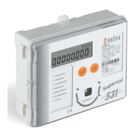
Sontex Supercal 531 Manual
Heat meter
Hide thumbs
Also See for Supercal 531:
- Installation manuallines (10 pages) ,
- Installation and manual (12 pages) ,
- Installation and manual (10 pages)
Table of Contents
Advertisement
Quick Links
Manual
Integrator
Integrator
Supercal
Supercal
531
Issue:
Document:
Manufacturer:
Technical modifications subject to change
cal modifications subject to change
Rev. 060611
Manual Integrator Supercal 531 06-06-2011
Manual Integrator Supercal 531 06
Sontex SA
2605 Sonceboz, Switzerland
Phone: +41 32 488 30 00
Fax: +41 32 488 30 01
Email:
sontex@sontex.ch
Internet:
www.sontex.ch
itzerland
Advertisement
Table of Contents

Subscribe to Our Youtube Channel
Related Manuals for Sontex Supercal 531


Summary of Contents for Sontex Supercal 531
- Page 1 Manual Integrator Integrator Supercal Supercal Issue: Rev. 060611 Document: Manual Integrator Supercal 531 06 Manual Integrator Supercal 531 06-06-2011 Manufacturer: Sontex SA 2605 Sonceboz, Switzerland itzerland Phone: +41 32 488 30 00 Fax: +41 32 488 30 01 Email: sontex@sontex.ch Internet: www.sontex.ch...
- Page 2 Author Description of Modification 030909 03.09.09 Data copied, layout adapted 151009 15.10.09 English Translation 121109 12.11.09 Completely reviewed 230410 23.04.10 Remove cooling energy chap. 3.6.3 060611 06.06.11 Modify Voltage tolerance for 24 VAC chap. 11.2.1 Manual Integrator Supercal 531 06-06-2011...
-
Page 3: Table Of Contents
Table of Contents Introduction ................... 6 Brief description ......................6 Advantages of the Supercal 531 ................. 6 Concept of the Heat Meter ..............7 Measuring concept ...................... 7 Integrator ........................7 Flow sensors ....................... 7 Temperature sensor ....................8 2.4.1 2-Wire-cable sensor ....................... - Page 4 8.2.2 The Supercal 531 in combination with standard (slow) flow sensors ........51 8.2.3 The Supercal 531 in combination with the flow sensor Superstatic 440 ....... 53 8.2.4 The „cut off“- function of the Superstatic 440 ................ 54 Special Functions ................56 Status message of the transistor outputs ..............
- Page 5 Standard version ........................62 11.3.2 Options of standard setting ....................64 11.3.3 Optional communication modules ..................65 Identification Plate Supercal 531 ............69 Mounting and Dimensional Drawing ..........70 Error Messages ................... 71 Project Planning .................. 72 Annexe ....................73 16.1...
-
Page 6: Introduction
1. Introduction 1.1 Brief description This Supercal 531 convinces by using state-of-the-art multi-functional technologies and by its modular concept. It can easily be adapted to our customer‘s requirements such as e.g. simplified system integration, tariff functions, data logger functions, universal data transfer or connection to existing process sys- tems. -
Page 7: Concept Of The Heat Meter
Please pay attention to where the flow sensor is installed („cold side“ or „warm side“) since the conversion from flowing volume into flowing mass is carried out on the basis of the temperature assigned to the place of installation. Manual Integrator Supercal 531 06-06-2011... -
Page 8: Temperature Sensor
If a length of more than 3 m is required, we recommend using shielded cables of the same length. The approval for the integrator Supercal 531 allows the use of two-wire temperature sensors up to a length of maximum 15 m and of four-wire sensors up to a max. cable length of 50 m. -
Page 9: 4-Wire-Cable Sensor
50 m. The connection cable must have four wires. The wire cross section should be at least 0.5 mm2. The insulation of the temperature sensor cable should be of PVC or silicone. Sontex recommends the use of silicone as insulator. -
Page 10: Installation Guideline Of Temperature Sensor Acc. To En1434
The connection cables of replaceable and conformity-approved temperature sensors installed in the supply and return pipe may be of a maximum length of 15 m; the cables must be of the same length. The cable cross section must be in line with EN 1434-2. Manual Integrator Supercal 531 06-06-2011... -
Page 11: Installation Guidelines
The installation guidelines acc. to EN 1434-2 and EN 1434-6 have to be followed strictly. Please note that the heat meter will only provide the requested precision and reliability if the local regula- tions for electric installations and the guidelines given by the manufacturer are followed. Manual Integrator Supercal 531 06-06-2011... -
Page 12: The Integrator Supercal 531
3. The Integrator Supercal 531 3.1 The modular concept The integrator Supercal 531 consists of: Measuring- and calibration-relevant upper part Base part Thanks to the modular concept of the integrator storing costs can be kept very low and replace- ment of the meter after expiry of the validity of the calibration is simple and reasonably-priced. -
Page 13: Integrator Base Part
Bar code label Optional mains- / battery supply 2 slotsfor optional communication modules rubber grommets/splash guard for connection cables base plate (not visible here) plug-in bracket for wall or top hat rail mounting (not visible here) Manual Integrator Supercal 531 06-06-2011... -
Page 14: Wiring Diagram
3.3 Flow measurement Type-approved flow sensors with a pulse or frequency output can be connected to the integrator Supercal 531. The integrator has the following input pulse factors: Up to 99'999’999 pulses/litre Up to 99'999’999 litre/pulse Manual Integrator Supercal 531 06-06-2011... -
Page 15: Calculation Of Flow
The measuring range approved acc. to MID is from 2 ° C to 200 ° C. There’s no homologation below 2 ° C according to the current applicable standards. By default, the integrator Supercal 531 is designed for temperature sensors Pt500. On request, Sontex can parameterise the integrator ex works for operation with Pt100. The connection of the temperature sensors is possible in two-wire and four-wire technology. -
Page 16: Tolerated Errors And Limit Values
„temperature sensor high“ in the return pipe. By default, the integrator Supercal 531 is checked acc. to the metrological measuring points of EN1434 (2006) for cooling and heating energy before leaving the factory. -
Page 17: Cooling Energy - Combined Cold-/Heat Meter
Thereafter, they are sealed and thus protected against unauthorized manipulation. If these calibration-relevant seals are damaged or removed, all warranty claims / service warranty claims as well as the calibration of the integrator are void. Manual Integrator Supercal 531 06-06-2011... -
Page 18: Possible Parameterisations
3.8 Possible parameterisations The Supercal 531 is parameterised with the software Prog531 over the optical interface or the ex factory M-Bus module. Each integrator is manufactured after order and parameterised in the fac- tory in accordance with the customer’s specifications. -
Page 19: Data Storage
4. Data Storage 4.1 Data storage over EEPROM The Supercal 531 has two non-volatile EEPROMs for storing data. The data are updated every hour in the non-volatile EEPROM of the upper part of the Integrator (MET). Thus, the data backup is kept even in case of power supply failure. All data are updated and stored automatically. -
Page 20: Data Storage With Backup-Batteries In The Mains Modules
By default, each mains module is supplied with a backup-battery which guarantees the current supply in case of a power failure. If a power failure occurs, the Supercal 531 is operated automati- cally in a battery-saving mode to ensure the continuity of the metrological functions. - Page 21 In backup-battery mode, the following functions of the Supercal 531 are still active: Temperature and flow measurement, energy calculation Tariff- and alarm functions Inputs A1 and A2 Outputs B1 and B2 Optical interface In battery-saving mode, all communication options are deactivated. The measuring cycle is re- duced to 30 seconds.
-
Page 22: Operational Concept
5. Operational Concept When designing the Supercal 531, main importance was placed on the user-friendliness. Thus, the integrator features an extremely large and clearly structured LCD-display. It has only two operator buttons to display the measuring data and for the menu navigation thus adding to the user- friendliness. -
Page 23: The Display Menu
User menu (Optional) Main menu Set day menu Montlyvalues 1...15 Error menu (only if errorr) *1234567 Average values 1...32 Service Test menu Maximum values Configuration (only with jumper 1...32 JP1 on main PCB) 1234567 Manual Integrator Supercal 531 06-06-2011... -
Page 24: The Operator Buttons
Pressing enter key and control key simultaneously, you go one level up in the menu tree. Regardless in which menu you are in the Supercal 531: after 3 minutes the integrator re- turns automatically to the first display of the main menu. -
Page 25: The Communication Concept
Data “ (point 11.), as from page 66. 6.1 Standard configuration By default, the Supercal 531 features an optical interface, a pulse input (terminal 10 and 11), two additional pulse inputs (A1 and A2) and two open-collector outputs (B1 and B2). -
Page 26: Pulse Input For Volume Measurement
If the time > 40 seconds or if X > 138 ms, a new wake up is sent. 6.1.2 Pulse input for volume measurement The Supercal 531 allows the connection of slow and fast flow sensors. To this end, two specific filters have been integrated (normal- or fast mode) which can be selected over the software Prog531. -
Page 27: Timing Of M-Bus Communication
6.1.6 Timing of M-Bus communication Manual Integrator Supercal 531 06-06-2011... -
Page 28: Optional Communication Modules
Flow Power Temperature high Temperature low Temperature difference Flow additional meter A1 Flow value additional meter A2 Up to two optional analogue modules can be operated in the integrator Supercal 531 at the same time. Manual Integrator Supercal 531 06-06-2011... -
Page 29: Relay Module
Volume additional meter A1 Volume additional meter A2 Up to two optional relay modules can be operated in the integrator Supercal 531 at the same time. When equipped with a relay module, the Supercal 531 must always be mains voltage supplied. -
Page 30: Module Rs-232 With Two Relay Outputs
The transmission rates are freely selectable between 300 and 38'400 baud. The readout can be done with a M-Bus read-out software. If equipped with a module RS-232 with two relay outputs, the Supercal 531 must always be mains voltage supplied. Each relay output is galvanically isolated and features two switching contacts. -
Page 31: Combined Module
Supercal 531 via the four freely selectable outputs to readout or control systems required e.g. for building management applications. -
Page 32: M-Bus Module With Two Relay Outputs
(or any kind of controller, control system and remote readout system) with the transmission of status messages, alarm and/or errors as relay output. When equipped with an M-Bus module with two relay outputs, the Supercal 531 must always be mains voltage supplied. -
Page 33: The Display Menus
99'999’999 (8 digits) The number of digits after the decimal point can be set at the factory or defined by an authorized laboratory. The displays of the cumulated energy for tariff 1 and tariff 2 are identical. Manual Integrator Supercal 531 06-06-2011... - Page 34 Possible flow units: /h, US-gallon/min Default parameterisation ex works: The number of digits after the decimal point can be set at the factory or by an authorized laboratory. Segment test All segments of the LCD-display appear. Manual Integrator Supercal 531 06-06-2011...
-
Page 35: Menu Set Day Values
01 is displayed. Now, the display sequence of set day 01 can be accessed and display after display can be read by repeatedly pressing the control key: Energy on set day 01 Manual Integrator Supercal 531 06-06-2011... - Page 36 The index „S1“ for set day 01 flashes. Press the control key: The index goes to „S2“. Confirm by pressing the enter key. Now the display sequence for set day S2 can be accessed by pressing the control key. Manual Integrator Supercal 531 06-06-2011...
-
Page 37: Menu Monthly Values
7.4 Menu monthly values The Supercal 531 records 15 monthly values, in the order 01 to 15. Every month, the cumulated values for energy, volume, additional pulse inputs and tariffs are re- corded. Index „01“ refers to the last monthly value, index „02“ refers to the month before last, the indices „03“... - Page 38 Now repeatedly press the control key. Thus the indices for all further monthly values (02 to 15, flashing) can be called. Confirm the display sequence for the requested monthly value by pressing the enter key. Manual Integrator Supercal 531 06-06-2011...
-
Page 39: Menu Average Values
7.5 Menu average values With the Supercal 531 a maximum of 32 average values can be readout and recorded. The aver- age time can be set between 1 minute and 45 days. The average values for the current power, flow, „temperature high“ and „temperature low“, tem- perature difference, flow A1 and flow A2 are recorded and displayed with the index „avg“. - Page 40 Alternatively, the display sequence for the requested average value can be selected by pressing the enter key. The average values can then be called by repeatedly pressing the control key. Manual Integrator Supercal 531 06-06-2011...
-
Page 41: Menu Maximum Values
5 = menu maximum values by pressing the enter key: The index for the menu navigation which is above „5“ flashes and the current performance of the last recorded maximum value with the index „01 max“ is displayed. Manual Integrator Supercal 531 06-06-2011... - Page 42 Alternatively, the display sequence for the requested maximum value can be selected by pressing the enter key. The maximum values can be called by repeatedly pressing the control key. Manual Integrator Supercal 531 06-06-2011...
-
Page 43: Menu Configuration
7.7 Menu configuration Here, the configuration values of the Supercal 531 can be checked and altered if required. Main menu Menu maximum values Max. value 01 current power Menu configuration Date Ttime Pulse factor Pulse units for Pulse factor for etc. - Page 44 Pulse factors of the additional pulse outputs B1 and B2 (indices B1 and B2) Integration period for calculating the average value Integration period for calculating the maximum value Primary address (index Ad) M-Bus Baud rate (index Br) M-Bus Manual Integrator Supercal 531 06-06-2011...
-
Page 45: Menu Service
7.8 Menu service Here, the configuration values of the Supercal 531 can be checked and altered if required. Main menu Menu configuration Time Menu service Customer etc. Manufactur- Software- Customer number er’s number version number (index Cn) (index SW) upper part... - Page 46 07 = M-Bus module relay 08 = M-Bus module Resistance value of the sensors Pt100 or Pt500 (index Pt) to be used. Place of installation of the flow sensor (index Ft); 0 = return pipe, 1 = supply pipe Manual Integrator Supercal 531 06-06-2011...
- Page 47 Operating hours of the Supercal 531 (index rh); indication of the operating time in hours Number of days without flow (index DF) Number of days without energy measurement (index DE) Display of current error (Err, error number) Duration of current error in minutes (index Erm) Error messages 1 –...
- Page 48 Duration of error in minutes (min), date (DA) and time (Hr) when the error began. Now press the control key again. Then the display returns to the identification number / customer number (index Cn) mentioned above. Manual Integrator Supercal 531 06-06-2011...
-
Page 49: Start-Up And Applications
The same applies for the start-up of the metering point where an expert has to check its proper functioning. After execution of this function check, the Supercal 531 has to be provided with seals. 8.1 Start-up of the Supercal 531 8.1.1 Backup battery... -
Page 50: Supercal 531
8.1.2 Supercal 531 8.1.2.1 Checking of date and time The correct setting of date and time is important so that the recorded data of the Supercal 531 can be allocated chronologically. They can be set with the service software Prog531 over the optical interface. -
Page 51: The Supercal 531 In Combination With Standard (Slow) Flow Sensors
8.2.1.1 Response time and accuracy of the flow calculation The time period during which the Supercal 531 carries out a new flow calculation is called re- sponse time. At the same time, the value of the current flow is updated... - Page 52 The maximum holding time always has to be adjusted specifically to the application. If, later, the heat meter is integrated into a controller application, it is important to check the setting of the maximum holding time. Manual Integrator Supercal 531 06-06-2011...
-
Page 53: The Supercal 531 In Combination With The Flow Sensor Superstatic 440
0.222 9.250 0.1360 9.444 0.0865 9.611 Example of the configuration of the integrator Supercal 531 combined with a flow sensor Super- static 440 with Qn 6 m3/h. Configuration 531: requested precision 2% (minimum: 50 pulses) Minimum holding time 5 seconds... -
Page 54: The „Cut Off"- Function Of The Superstatic 440
8.2.4 The „cut off“- function of the Superstatic 440 When combining the integrator Supercal 531 with the static flow sensor Superstatic 440, the possi- ble flow measuring range is set and limited by a lower and upper threshold value („cut off“ and „flow saturation“) at the factory. - Page 55 The threshold values of the „cut off“- function have to be regarded as autonomous from the other two additional threshold values. Table with the factory-set threshold values acc. to PTB metrological class C Table with the factory-set threshold values acc. to OIML R75 1988 Manual Integrator Supercal 531 06-06-2011...
-
Page 56: Special Functions
9. Special Functions The special functions of the Supercal 531 can either be activated at the factory or with the service software Prog531. 9.1 Status message of the transistor outputs The Supercal 531 allows the transmission of the status messages to the transistor outputs. The displayed statuses can be defined over the threshold values. -
Page 57: Open System (In Development)
9.8 Energy-assessing hot water meter / 1 sensor system The integrator Supercal 531 (Supercal 531) can be set at the factory as energy-assessing hot wa- ter meter. Up to12 fixed monthly return temperatures can be set (via the tariff functions) as fixed values ac- cording to the customer’s requirements and used as control elements. -
Page 58: Seals And Operating Modes
As soon as the jumper is removed, the Supercal 531 goes back to normal mode automatically is removed, the Supercal 531 goes back to normal mode automatically is removed, the Supercal 531 goes back to normal mode automatically. -
Page 59: Calibration Mode
10.3 Calibration Mode The Supercal 531 may only be switched over to calibration mode by authorized personnel. To ac- cess the calibration mode, the seal (C) on the back side of the integrator cover has to be removed. As soon as the seal is damaged or removed, the validity of the official calibration test and the warranty from Sontex are void. -
Page 60: Technical Data
EN1434-1 11.2 Mains supplies The Supercal 531 can be supplied by battery or mains modules. They can be retrofitted at any time. The mains modules are provided with a jumper. The backup-battery can be activated or deacti- vated by this jumper. -
Page 61: Mains Module With Backup-Battery
D-cell as battery with a service life of 6 years. Lithium C - cell Nominal voltage 3.6 V Service life up to 6 + 1 years (in combination with autarkic flow sen- sors) Maximum ambient temperature 55° C Manual Integrator Supercal 531 06-06-2011... -
Page 62: Communication Features
55° C 11.3 Communication features The features of the Supercal 531 (in the integrator lower part) mentioned in point 11.3.1 are stan- dard features ex factory and the features mentioned in point 11.3.2 can be installed additionally in our factory. - Page 63 Max. pulse frequency 5 Hz (+/- 20%) Fast mode: Voltage max. 30 VDC Power max. 100 mA Voltage drop approx. 1.3 V at 20 mA Pulse type linear or scaled pulses Max. pulse frequency 10 kHz (+/- 20%) Manual Integrator Supercal 531 06-06-2011...
-
Page 64: Options Of Standard Setting
300...9’600 baud (… 4800 Baud on battery!) Modify with SW Prog531 Data structure variable Supply voltage: UMU,M(MARK) 36 V UMU,S (SPACE) 24 V UM,M (SPACE) 12 V UM,S (MARK) 11,3 V Supply current: 1,5 mA 20 mA Manual Integrator Supercal 531 06-06-2011... -
Page 65: Optional Communication Modules
30m, depending on the local conditions and the structural engineering conditions Radio telegram: The radio telegram of the integrator Supercal 531 is structured in accordance with the M-Bus pro- tocol to EN1434-3. For radio readout, the following telegrams are available:... - Page 66 500 mW Max. forward resistance Typical output capacitance 150 pF Max. frequency 100 Hz Pulse duration 5..400 ms possible in steps of 1ms Error status closed (no error) Alarm condition open (no alarm) Circuit diagram: Manual Integrator Supercal 531 06-06-2011...
- Page 67 RS-232 module with two relay out- puts Relay: acc. to specification relay module Analogue: acc. to specification analogue module with two outputs 0..20 mA, 4..20 mA or 0..10 VDC Analogue inputs 4 (external voltage supply) Analogue outputs Manual Integrator Supercal 531 06-06-2011...
- Page 68 Data structure variable Relay: see specification relay module Connection diagram: M-Bus module (see 6.2.7) Definition of interface acc. to EN 1434-3 Interface potential-free, protected against reverse polarity Transmission rate 300...9'600 baud Data structure variable Connection diagram: Manual Integrator Supercal 531 06-06-2011...
-
Page 69: Identification Plate Supercal 531
12. Identification Plate Supercal 531 In accordance with PTB / MID the following data are stated on the identification plate or on the integrator upper part: Manufacturer’s logo Sontex standard Ownership or metering point number optional Product description Supercal 531... -
Page 70: Mounting And Dimensional Drawing
13. Mounting and Dimensional Drawing The integrator Supercal 531 can be installed in different ways: Wall-mounting Compact mounting on a flow sensor Top hat rail mounting Manual Integrator Supercal 531 06-06-2011... -
Page 71: Error Messages
14. Error Messages The Supercal 531 indicates an existing error on the LCD display with the designation „Err“ and a numerical code: In case several errors occur at the same time, the numbers of error codes are listed and displayed. -
Page 72: Project Planning
The integrator Supercal 531 features state-of-the-art technology and is in compliance with EN1434. If the integrator is operated outside the specifications defined in this manual or is not operated in accordance with the regulations, all service and warranty claims toward Sontex are null and void. Local regulations... -
Page 73: Annexe
Therefore the development of the NOWA-adapter was necessary. Schematic diagram of an official calibration test rig Prüfstandssteuerung Wärmezähler Prüf- und NOWA Abgleichadapter Prüfstand Referenz 0,1234 m3 Waage / MID Manual Integrator Supercal 531 06-06-2011... - Page 74 High security with regard to errors in the handling of the test procedures Lower production and quality assurance costs for the integrator manufacturers Improved consumer protection The NOWA.EXE file allows the adaptation to various applications and firmware configuration of modern integrators. Manual Integrator Supercal 531 06-06-2011...
-
Page 75: Sontex Nowa.exe V1.03
10% of current meter setting Min. measurement duration: 90s Max. deviation current flow: -50% / +10% The effective CURRENT values which are sent by the test rig at least once during the test cycle are used for the comparison. Manual Integrator Supercal 531 06-06-2011... - Page 76 Check if run is permissible value point with current test mode. If “Yes” (JA): Save under the giv- en index. Request „adjustment by test rig“: checking of the own measured values of the test points for suitability for the adjustment. In case of feedback signal „YES“: carry out adjustment Manual Integrator Supercal 531 06-06-2011...
- Page 77 Standalone-mode in WinXP (with the respective drivers) In the file OPTIONS.CFG, the options can be registered line by line or within one line (with space character or put in commas). Format of the command line for options: NOWA [/SON:Option1,Option2,Option3,…etc. Manual Integrator Supercal 531 06-06-2011...
-
Page 78: Tariff Functions
16.2 Tariff Functions Manual Integrator Supercal 531 06-06-2011... - Page 79 Notes Manual Integrator Supercal 531 06-06-2011...
- Page 80 Technical Support For technical support, please contact your local Sontex representative or Sontex SA directly. Hotline Sontex: sontex@sontex.ch +41 32 488 30 04 Manual Integrator Supercal 531 06-06-2011...
Need help?
Do you have a question about the Supercal 531 and is the answer not in the manual?
Questions and answers
How do i change the read out from kwh to Mwh? on a Sontex 531
The Sontex Supercal 531 allows energy display in different units, including kWh and MWh. The readout settings can be adjusted using the service software Prog531 via the optical interface. To change the readout from kWh to MWh, follow these steps:
1. Connect the Supercal 531 to the service software Prog531 using the optical interface.
2. Access the configuration settings.
3. Locate the energy display unit option.
4. Change the unit from kWh to MWh.
5. Save the changes and remove the jumper if necessary to return to measuring mode.
This process ensures the display shows energy measurements in MWh instead of kWh.
This answer is automatically generated
How do I access previous meter readings
You can access previous meter readings on the Sontex Supercal 531 by viewing the recorded error messages and historical data stored in the device. The meter stores the last 10 recorded errors, including their error codes and timestamps. You can navigate through this data using the control key on the device. Additionally, readings such as operating hours, days without flow, and days without energy measurement can be accessed through the display menu.
This answer is automatically generated