Table of Contents
Advertisement
Quick Links
- 1 4Re Vehicle Installation Instructions
- 2 Standard Parts Included for a Wireless Installation
- 3 Quick Overview of Installation
- 4 Connecting the Power Cable to the Vehicle Battery
- 5 Connecting the External Inputs Cable
- 6 Poe Ethernet Cable Connections
- 7 Poe Switch
- Download this manual
See also:
User Manual
Advertisement
Table of Contents

Subscribe to Our Youtube Channel
Related Manuals for Watchguard 4RE


Summary of Contents for Watchguard 4RE
-
Page 1: 4Re Vehicle Installation Instructions
4RE Vehicle Installation Instructions WatchGuard Video WGD00085 REV B1... -
Page 2: Table Of Contents
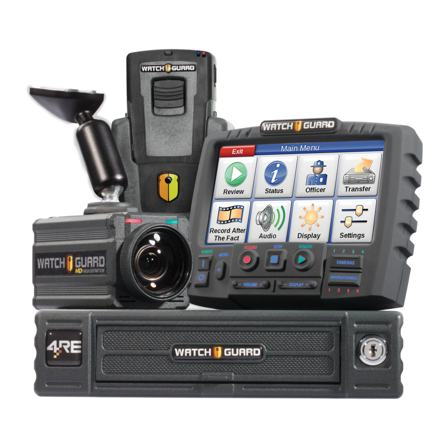
This document is not meant as an exclusive blueprint for any particular vehicle, but general instructions for a 4RE DVR installation. This instruction manual errs on the side of more information for those persons/installers who may be new to the installation process. If there is an issue or question pertaining to a particular vehicle make and model, please direct your questions to the WatchGuard Video Customer Service Department at 1-800-605-MPEG (6734). -
Page 3: Standard Parts Included For A Wireless Installation
4RE, Cable, HDMI, Front Cam, Straight, 15' 1 WGP01688 4RE, Cable, Mezzanine, VGA to 4-Analog Cam, 7' 1 WGP01803 4RE, Cable, HDMI, Port 2, Backseat Camera, 2-Pin 16' 1 WGA00348 Camera Assembly, 4RE, HD Front/Cabin Combo, Glass Mount 1 WGA00391... -
Page 4: Recommended Tools
Vehicle Installation Instructions Recommended Tools Drill and bits ¾ inch bit for antenna mounting o Philips bits Coarse sandpaper 60 or 80 Grain 10-30 feet of 16-20 gauge primary wire for extending input cable connections if necessary ... -
Page 5: Before Installing The 4Re System In A Vehicle
Vehicle Installation Instructions Before installing the 4RE system in a vehicle Begin by ensuring that you have received all the parts for the 4RE system. If you have any missing or damaged parts please call WatchGuard Video Customer Service at 1-866-384-8567. -
Page 6: Quick Overview Of Installation
Vehicle Installation Instructions Quick Overview of Installation 1. Gather all tools and materials 2. Mount Radio antenna and route cable 3. Configure and mount Radio Bullet 4. Install external inputs/power cable 5. Route cables for: a. Camera(s) b. Wireless Microphone c. -
Page 7: Starting Your Installation
Caution: There are 2 different types of antenna mounts – a thru-hole antenna (NMO mount) which requires drilling a ¾” hole in the metal of the vehicle OR a magnetic mount which does not require drilling a hole. WatchGuard Video recommends using the NMO mount antenna if possible for better signal strength. - Page 8 Vehicle Installation Instructions 2. Drill a ¾ inch hole for the antenna cable. [Figure 5] Figure 3 Figure 4 Figure 5 3. After the hole is made, sand the paint off the interior metal around the hole to ensure a good ground.
- Page 9 Vehicle Installation Instructions 8. Re-attach the NMO nut with the o-ring facing down to create a seal. [Figure 11] 9. Tighten the nut with a 24mm or 15/16’’ open end wrench ensuring that the mount stays centered in the hole and that the mount does not turn and kink the cable. [Figure 12] Warning: Do not use a Channel lock pliers as it could damage the NMO nut.
-
Page 10: Mounting The Bullet Radio
Vehicle Installation Instructions Mounting the Bullet Radio For Instructions on how to configure the Bullet with the wireless network see the document: Evidence Library Administrative Guide Warning: In order to configure the Bullet it must be attached to a POE power adapter and the antenna before connecting to your computer. -
Page 11: Connecting The Power Cable To The Vehicle Battery
Vehicle Installation Instructions Connecting the Power Cable to the Vehicle Battery The power/external inputs cable looks like the following: Figure 15 1. Route the power cable to the vehicle battery. Note: For the Chevrolet Tahoe with a dual battery configuration, use the passenger side battery if possible. - Page 12 Vehicle Installation Instructions Figure 16 Figure 17 3. Pull the power cable to the battery. 4. Pull excess cable out past the battery side of the firewall (leave some slack for a drip loop). Grommet access through firewall Figure 18 5.
- Page 13 Vehicle Installation Instructions 8. Strip back ½ inch on the red, black and additional Chassis ground cable. [Figure 19] Figure 19 9. Twist the black ground, the un-insulated silver drain wire, and chassis ground wires together [Figure 20] and crimp on a ring terminal to be attached to the battery negative ground post. [Figure 21] Figure 20 Figure 21...
- Page 14 Vehicle Installation Instructions 11. Connect the positive and negative wires to the appropriate vehicle battery posts. [Figure 23] Positive (+) side Figure 23 12. Route the power harness inside the engine bay in such a manner that it will not interfere with the vehicle.
-
Page 15: Connecting The External Inputs Cable
Vehicle Installation Instructions Connecting the External Inputs Cable Before connecting the input cable it is necessary to know the wiring scheme for connecting the external inputs cable. All the inputs generally require positive 8-12 volts of power to activate the corresponding device. -
Page 16: Emergency Lights - Blue With White Stripe
Vehicle Installation Instructions Emergency Lights – Blue with White Stripe The Emergency Lights input should connect to a positive 12 volt switched power source that provides voltage when the overhead lights are activated. [Figure 25] Note: Some emergency light manufacturers use negative 12 volt or ground triggers. In those cases an additional relay may need to be incorporated into the wiring scheme to provide positive 12 volt power to the input wire. -
Page 17: Siren - Pink And Green Wires
Vehicle Installation Instructions Siren – Pink and Green Wires The siren input wire consists of two wire connections – the green wire is connected to the siren speaker ground feed and the pink wire is connected to the positive siren speaker feed. When the siren is activated then the siren input will sense voltage. -
Page 18: Auxiliary - Solid Blue Wire
Vehicle Installation Instructions Auxiliary – Solid Blue Wire Depending on the installation this input wire may or may not be used. The input should be connected to a device that provides positive 12 volt switched power to be used as an alternate trigger. For example, the input can be connected to a shotgun mount electric release button or a K-9 electric kennel door release. -
Page 19: Brake Input - Black Wire With White Stripe
Vehicle Installation Instructions Brake Input – Black Wire with White Stripe The brake input should connect to a positive 12 volt switched power activated when the brake pedal is depressed. When the brakes are pressed, the wire should get 12 volts. Depending on the installation this wire may or may not be used. -
Page 20: Chassis Ground - Yellow Wire
Figure 29 Warning: Improperly grounded chassis ground wire connections will result in unpredictable DVR operation and performance. Note: WatchGuard Video recommends that the Chassis ground always be grounded to the Negative (ground) post on the vehicle battery. WGD00085 REV B1... -
Page 21: Power Over Ethernet (Poe) Adapter - Orange And Brown
Vehicle Installation Instructions Power Over Ethernet (PoE) Adapter – Orange and Brown The assembly consists of a POE adapter which provides power from the DVR to the Bullet Radio and two Ethernet cables that connect from the DVR to the Bullet radio. The orange wire is positive 12 volt power and the brown wire is ground. -
Page 22: Mdc/Mdt Configuration (Optional)
Vehicle Installation Instructions MDC/MDT Configuration (Optional) Note: 1 additional Ethernet cables will be needed (this should be included with the MDC package). PoE Switch When the configuration of the DVR uses a MDC/ MDT (Laptop connection to DVR), a PoE Switch is needed. -
Page 23: Radar Interface Cable (Optional) - Purple/Black/Gray Connector
Vehicle Installation Instructions Radar Interface Cable (Optional) – Purple/Black/Gray connector The radar interface cable connects from the radar unit into the radar interface connector on the input cable. Please refer to the specific installation instructions included with the radar interface cable. GPS Antenna (Optional) The GPS cable has a threaded antenna ferrule and should be attached to the GPS port on the back of the DVR. -
Page 24: Mounting The Remote Display Control Panel
Vehicle Installation Instructions Mounting the Remote Display Control Panel Depending on the type of vehicle you have, mounting the Remote Display Control Panel will differ with each installation. Please refer to the display mounting documentation that came with your specific bracket. -
Page 25: Cabin Microphone
Vehicle Installation Instructions Cabin Microphone The cabin microphone utilizes a 3.5mm headphone style jack. The cabin microphone can be mounted anywhere in the vehicle cabin as necessary to record the audio inside the vehicle. The cabin microphone should not be mounted within 5-6 inches of the wireless microphone if possible as it can cause some interference. - Page 26 Vehicle Installation Instructions Figure 33c Figure 33d Figure 33e WGD00085 REV B1 Page 26...
-
Page 27: Front Hd Combination Camera
Vehicle Installation Instructions Front HD Combination Camera The combination camera is mounted on the windshield approximately one inch to the right of the rear view mirror. The camera uses a mirror button that is glued to the top of the windshield. Mount the button as high up on the windshield as possible to reduce blocked vision to the driver. - Page 28 Vehicle Installation Instructions Attach the camera to the Button 1. After the button has cured and set, connect the mini HDMI cable to the camera (round edge towards the front of the camera [Figure 36-38]. Front Figure 36 Figure 37 Figure 38 2.
- Page 29 Vehicle Installation Instructions Rear Seat Camera – Below is an example of mounting the rear camera on a caged Crown Vic. Find the best place to install the camera in the specific vehicle (as it may vary vehicle to vehicle) In this scenario zip ties were used to secure the camera around the cage tubing ensuring that the ties are tight enough that the window frame of the cage will not close and rub against them.
-
Page 30: Test Functions Of Dvr
Vehicle Installation Instructions Test Functions of DVR Ensure all components are connected properly by performing a few tests. 1. Connect 7.5 amp Fuse at the Battery 2. Start the vehicle and power on system by pressing the on ( ‘I’) button, if it does not start automatically 3. - Page 31 Vehicle Installation Instructions 4RE Vehicle Installation Instructions WatchGuard Video 415 Century Parkway Allen, Texas 75013 1-800-605-6734 Toll Free Sales 1-866-384-8567 Toll Free Support CustomerService@watchguardvideo.com WGD00085 REV B1 Page 31...
Need help?
Do you have a question about the 4RE and is the answer not in the manual?
Questions and answers
Looking for the main power cable connect to the hard drive due to the camera system being in but has a black screen and won’t come on
The main power cable for the WatchGuard 4RE camera system is the WGP02073-300 cable.
This answer is automatically generated