Table of Contents
Advertisement
Quick Links
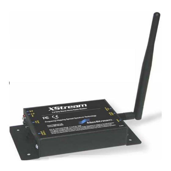
XStream-PKG-T™ Telephone RF Modem
XStream Telephone RF Modem
RF Module Operation
Telephone Module Operation
RF Communication Modes
Appendices
Product Manual
XStream RF Modem Part Numbers:
Reliable 900 MHz & 2.4 GHz Stand-alone RF Modems by MaxStream, Inc.
355 South 520 West, Suite 180
Lindon, UT 84042
Phone: (801) 765-9885
Fax: (801) 765-9895
rf-xperts@maxstream.net
www.maxstream.net (live chat support)
v5.x00
X09-001PK...-T...
X09-009PK...-T...
X09-019PK...-T...
X24-009PK...-T...
XH9-001PK...-T...
X24-019PK...-T...
XH9-009PK...-T...
XH9-019PK...-T...
M100111
2006.02.24
Advertisement
Table of Contents

Related Manuals for MaxStream 9XStream-PKG-T


Summary of Contents for MaxStream 9XStream-PKG-T
- Page 1 X24-009PK…-T... XH9-001PK…-T... X09-009PK…-T… X24-019PK…-T… XH9-009PK…-T… X09-019PK…-T… XH9-019PK…-T… Reliable 900 MHz & 2.4 GHz Stand-alone RF Modems by MaxStream, Inc. 355 South 520 West, Suite 180 Lindon, UT 84042 Phone: (801) 765-9885 Fax: (801) 765-9895 rf-xperts@maxstream.net M100111 www.maxstream.net (live chat support)
- Page 2 XStream‐PKG‐T™ Telephone RF Modem – Product Manual v5.x00 [2006.02.24] © 2006 MaxStream, Inc. All rights reserved No part of the contents of this manual may be transmitted or reproduced in any form or by any means without the written permission of MaxStream, Inc. XStream™, XStream‐PKG‐R™ and XStream‐PKG‐T™ are registered trademarks of MaxStream, Inc. Technical Support: Phone: (801) 765‐9885 Live Chat: www.maxstream.net E‐Mail: rf‐xperts@maxstream.net © 2006 MaxStream, Inc., Confidential and Proprietary ...
-
Page 3: Table Of Contents
Appendix C: Additional Information 2.1. Modes of Operation 9 1-Year Warranty 61 2.1.1. Idle Mode Ordering Information 61 2.1.2. Transmit Mode Contact MaxStream 62 2.1.3. Receive Mode 2.1.4. Sleep Mode 2.1.5. Command Mode 2.2. RF Module Configuration 15 2.2.1. Command Reference Table 2.2.2. -
Page 4: Xstream Telephone Rf Modem
Devices that contain XStream RF Modems inherit MaxStream’s FCC Certification ISM (Industrial, Scientific & Medical) frequency band Manufactured under ISO 9001:2000 registered standards 9XStream-PKG-T (900 MHz) RF Modems approved for use in US, Canada, Australia, Israel (and more). © 2006 MaxStream, Inc., Confidential and Proprietary... -
Page 5: Product Overview
XStream‐PKG‐T™ Telephone RF Modem – Product Manual v5.x00 [2006.02.24] 1.2. Product Overview When networked with other MaxStream Radio Modems (RS-232/485, Ethernet, USB, etc.), the XStream PKG Telephone Modem provides a transparent wireless link between serial devices and telephone modems. The telephone interface extends MaxStream’s over-the-air range with the reach of any PSTN (Public Switched Telephone Network). -
Page 6: External Interface
0 Green LED ON = Weak (< 10 dB fade margin) (Red light is on when powered, Module. Fade Margin = The difference between the incoming signal off briefly during RF transmission) strength and the modem’s receiver sensitivity. © 2006 MaxStream, Inc., Confidential and Proprietary ... -
Page 7: Block Diagram
This is the default state of the RF Modem (when DB-9 is not connected). Refer to the RF Module Configuration [p15] and Telephone Module Configuration [p20] sections for more information about configurations of the on-board Telephone and RF Modules. © 2006 MaxStream, Inc., Confidential and Proprietary ... -
Page 8: Pin Signals
Telephone Modem to DI3 (SLEEP) of the on-board RF Module. Non-populated J1 and J5 jumpers are also available for bypassing the high input voltage regulators. This would allow the RF modem to be powered with a 5 volt supply. Contact MaxStream Technical Support for more information. © 2006 MaxStream, Inc., Confidential and Proprietary... -
Page 9: Rf Module Operation
• Valid RF data is received through the antenna (Receive Mode) • Command Mode Sequence is issued (Command Mode) • Sleep Mode condition is met (Sleep Mode) After responding to any of the preceding conditions, the modem automatically transitions back into Idle Mode. © 2006 MaxStream, Inc., Confidential and Proprietary ... -
Page 10: Transmit Mode
If more data is pending, the transmitting modem assembles a subsequent packet for transmission. RF Packet The RF packet is the sequence of data used for communicating information between MaxStream Modems. An RF Packet consists of an RF Initializer and RF Data. Figure 2‐03. RF Packet Components ... -
Page 11: Receive Mode
RF data. If serial data is stored in the DI buffer while the modem is in Receive Mode, the serial data will be transmitted after the modem is finished receiving data and returns to Idle Mode. © 2006 MaxStream, Inc., Confidential and Proprietary ... -
Page 12: Sleep Mode
When the module awakens to listen for data, DO2 is asserted and any data received on the DI Pin is transmitted. PWR is also de-asserted (low) when the module is in Cyclic Sleep Mode. © 2006 MaxStream, Inc., Confidential and Proprietary ... - Page 13 Figure 2‐06. Correct Configuration (LH > SM): Length of the wake‐up initializer exceeds the time interval of Cyclic Sleep. The receiver is guaranteed to detect the wake‐up initializer and receive the accompanying payload data. Figure 2‐07. Incorrect Configuration (LH < SM): Length of wake‐up initializer is shorter than the time interval of Cyclic Sleep. This configuration is vulnerable to the receiver waking and missing the wake‐up initializer (and therefore also the accompanying payload data). © 2006 MaxStream, Inc., Confidential and Proprietary ...
-
Page 14: Command Mode
NOTE: The XStream-PKG-T RF Modem automatically powers up to a Command Mode for the on- board telephone module, the on-board RF Module does not. To enter RF Module into Command Mode for the purpose of programming the module, follow the refer to the RF Module Configuration section [next page]. © 2006 MaxStream, Inc., Confidential and Proprietary ... -
Page 15: Rf Module Configuration
Transmit Error Count 0 – 0xFFFF Diagnostics TT v4.22* 0x1A (26d) Streaming Limit 0 – 0xFFFF [0 = disabled] Networking & Security 0xFFFF 0x14 (20d) Firmware Version 0 x 0xFFFF [read-only] Diagnostics 0x08 (8d) Write (Special) * Firmware Version in which the command was first introduced. All subsequent versions also support the command. © 2006 MaxStream, Inc., Confidential and Proprietary ... -
Page 16: At Command Mode
• Observe Guard Time After (ATAT = 0x0A, no characters sent for one second) IMPORTANT: The default Command Sequence Character (“-“) is unique to the XStream-PKG-T Telephone RF Modem. All other MaxStream Radio Modems use the “+” character as their default. Send AT Commands: When using the “Terminal”... - Page 17 Select the ‘Load’ button, then navigate to and open the appropriate profile. Profiles carry a “.pro” file extension and are located in the ‘Profiles’ folder of the MaxStream CD. Select the ‘Write’ button to save RF module default values to non-volatile memory.
-
Page 18: Binary Command Mode
If binary programming is not enabled (RT ≠ 1), the RF module will not recognize that the CMD pin is asserted and therefore will not recognize the data as binary commands. © 2006 MaxStream, Inc., Confidential and Proprietary ... - Page 19 (Most significant byte of parameter bytes) (Send WR (Write) Command) De-assert CMD (Pin is driven low). (Exit Binary Command Mode) Note: is high when command is being executed. Hardware flow control must be disabled as will hold off parameter bytes. © 2006 MaxStream, Inc., Confidential and Proprietary ...
-
Page 20: Telephone Module Operation
The Telephone Module features a rich set of AT commands that allow flexibility in operations. On power-up or reset, the Telephone Module operates in command mode and will accept AT commands either from an RS-232 serial cable or from another MaxStream RF Modem (PKG-R, PKG-U, etc.) over a wireless link. - Page 21 Line speed or DTE connection at 14400 bps CONNECT 19200 Line speed or DTE connection at 19200 bps CONNECT 38400 Line speed or DTE connection at 38400 bps CONNECT 57600 Line speed or DTE connection at 57600 bps © 2006 MaxStream, Inc., Confidential and Proprietary ...
-
Page 22: Command Reference Tables
NO CARRIER will be reported. n = 4 Enables monitoring of busy tones; sends all messages. (default) n = 0 Soft reset and restore profile 0 n = 1 Soft reset and restore profile 1 © 2006 MaxStream, Inc., Confidential and Proprietary ... - Page 23 If the number n (or the value v on a write) is out of range or invalid, the module will return the “ERROR” message. All S-Parameter values and responses are in decimal format. All S-Parameters can be read using “&V” command [Table 3-03]. © 2006 MaxStream, Inc., Confidential and Proprietary ...
- Page 24 Flash (“!”) dial modifier in dial string. [x 10 ms] not configurable) Disconnect Inactivity Timer. The length of time that the module 0 - 255 will stay online before disconnecting when no data is sent or 0 (disabled) [x 10 seconds] received. © 2006 MaxStream, Inc., Confidential and Proprietary ...
-
Page 25: Telephone Module Configuration Example
AT&W0 <CR> OK (Stores current settings as Profile “0”) AT&Y0 <CR> OK (Hard reset then restores Profile “0”) AT&V <CR> (… Lists active & stored profile values) OK At&F0 <CR> OK (Restores factory default configuration “0”) * <CR> Each command line is concluded with a carriage return (<CR> or “Enter” key) © 2006 MaxStream, Inc., Confidential and Proprietary ... -
Page 26: Rf Communication Modes
Acknowledged Mode [p32], Multi-Streaming Mode [p34] Peer-to-Peer Modems remain synchronized without use of a master/server. Each modem shares the roles of master and slave. MaxStream’s peer-to- Definition peer architecture features fast synch times (35ms to synchronize modems) and fast cold start times (50ms before transmission). -
Page 27: Addressing
“ANDed” with the Address Mask of the RX modem. Figure 4‐03. Address Recognition (Receiving Modem) TX_DT = Transmitter Destination Address RX_DT = Receiver Destination Address RX_MY = Receiver Source Address NOTE: For more information regarding addressing and masks, refer to Application Note ‘XST- AN004b’. (Located on the MaxStream CD and on the web: www.maxstream.net) © 2006 MaxStream, Inc., Confidential and Proprietary ... -
Page 28: Basic Communications
0 and (RN-1) if the local (i.e. receiving modem’s) RN parameter is set to a non-zero value. These delays are intended to lessen congestion following long bursts of packets from a single transmitting modem, during which several receiving modems may have become ready to transmit. © 2006 MaxStream, Inc., Confidential and Proprietary ... -
Page 29: Repeater Mode
This mechanism eliminates the need for configuring specific routes. The network is self- organizing and self-healing so that the system is able to receive transmissions in the event of a modem going down. Figure 4‐05. Sample Repeater Network Topology © 2006 MaxStream, Inc., Confidential and Proprietary ... - Page 30 Where L is the length of the transmitted packet in milliseconds, DS is the number of delay slots to wait, RSSI is the received signal strength in dBm, RN is the value of the RN register and RandomInt(A,B) is a function that returns a random integer from A to B-0 © 2006 MaxStream, Inc., Confidential and Proprietary ...
- Page 31 32 byte packet in 12 ms for a round trip with UART transfer times of ~30ms or 33 polls per second (1066 bytes per second) with no repeaters. With two repeaters the time would be ~100ms round trip time for 10 polls per second or 320 bytes per second network throughput with two repeaters. © 2006 MaxStream, Inc., Confidential and Proprietary ...
-
Page 32: Acknowledged Communications
Idle Mode and may receive RF data. This can h the effect of increasing the ba ck-off delay, as the radio cannot return to RF transmit (or retransmit) mode as long as it is receiving RF data. © 2006 MaxStream, Inc., Confidential and Proprietary ... - Page 33 RN parameter is set to a nonzero value. These delays are intended to lessen congestion following long bursts of packets from a single transmitting modem, during which several receiving modems may have themselves become ready to transmit. © 2006 MaxStream, Inc., Confidential and Proprietary ...
-
Page 34: Multi-Streaming Mode
CGP (Connection Grant Packet) is broadcast to all remote modems in the network to communicate the base in engaged in an exclusive connection. Upon receipt of the CGP notification, remote modems will wait for a DGP (Disconnect Grant Packet) before attempting again to send data to the base modem. © 2006 MaxStream, Inc., Confidential and Proprietary ... - Page 35 DI3 line high. If no connection is active, the de-assertion is ignored. A remote will request a disconnect if DI3 is de-asserted and the remote is currently connected the base. Refer to DR (DI3 Configuration) Command. A remote or a base modem receives the ATDC (Disconnect) Command. © 2006 MaxStream, Inc., Confidential and Proprietary ...
- Page 36 The CGP and DGP packets will be sent RR times to begin and end the global connection respectively. The connection can be terminated by CE, CB timers, DI3 or ATDC Command as any other connections. © 2006 MaxStream, Inc., Confidential and Proprietary ...
- Page 37 (low) when there is no connection. A base modem can also be set to send the “CONNECT XXXX” string (where “XXXX” is the connecting modem’s MY (Source Address) parameter) anytime a connection is established. Refer to CM (Connection Message) Command. © 2006 MaxStream, Inc., Confidential and Proprietary ...
-
Page 38: Appendix A: Agency Certifications
IMPORTANT: The 9XStream (900 MHz) and 24XStream (2.4 GHz) OEM Modems have been certified by the FCC for use with other products without any further certification (as per FCC section 2.1091). Changes or modifications not expressly approved by MaxStream could void the user’s authority to operate the equipment. -
Page 39: Oem Labeling Requirements
900 number or any number for which charges exceed local or long distance transmission charges.) This equipment must not be used on party lines. Connection to party line service is subject to state tariffs. Contact state public utility commission for information. © 2006 MaxStream, Inc., Confidential and Proprietary ... -
Page 40: Antenna Usage
This test is called the Specific Absorption Rate (SAR) testing and measures the emissions from the radio modem and how they affect the person. Over 100 additional antennas have been tested and are approved for use with MaxStream 900 MHz Radio Modems (including “Mag Mount”, “Dome”, “Multi-path” and “Panel” antennas). -
Page 41: Fcc-Approved Antennas
Type Gain Application Min. Separation Distance Yagi 6.2 dBi Fixed/Mobile ** 20 cm Yagi 7.2 dBi Fixed/Mobile ** 20 cm MaxStream A09-Y8 Yagi 8.2 dBi Fixed/Mobile ** 20 cm Yagi 9.2 dBi Fixed/Mobile ** 20 cm Yagi 10.2 dBi Fixed/Mobile **... -
Page 42: Ic (Industry Canada) Certification
Integrator is responsible for its product to comply with IC ICES-003 & FCC Part 15, Sub. B - Unintentional Radiators. ICES-003 is the same as FCC Part 15 Sub. B and Industry Canada accepts FCC test report or CISPR 22 test report for compliance with ICES-003. © 2006 MaxStream, Inc., Confidential and Proprietary ... -
Page 43: Appendix B: Development Guide
XStream‐PKG‐T™ Telephone RF Modem – Product Manual v5.x00 [2006.02.24] Appendix B: Development Guide Mechanical Drawings Figure B‐01. XStream‐PKG‐T (Telephone) RF Modem (RJ‐11 and DB‐9 Connectors) Figure B‐02. XStream‐PKG‐T (Telephone) RF Modem (LEDs) © 2006 MaxStream, Inc., Confidential and Proprietary ... -
Page 44: Rf Module Configuration
XIB-R (RS-232/485) and XIB-U (USB) Interface Boards. To Install X-CTU Software: Double-click the “setup_X-CTU.exe” file then follow prompts of the installation screens. This file is located in the “software” folder of the MaxStream CD and under the ‘Downloads’ section of the following web page: www.maxstream.net/support/ Figure B‐03. ... -
Page 45: Rf Module Commands (Long Descriptions)
BD register. For example, a rate of 19200 bps can be set by sending the following command line "ATBD4B00". NOTE: When using MaxStream’s X-CTU Software, non-standard interface data rates can only be set and read using the X-CTU ‘Terminal’ tab. Non-standard rates are not accessible through the ‘Modem Configuration’... - Page 46 Beware that this will also mean that AT Command Mode cannot be entered by manually typing the AT command sequence characters (“---” by default) because the BT timeout will occur faster than the characters can be typed. © 2006 MaxStream, Inc., Confidential and Proprietary ...
- Page 47 Parameter Range: 0 – 0xFFFF for the time specified. [x 10 milliseconds] Default Parameter Value: 0x64 (1 decimal second) Number of bytes returned: 2 Related Commands: CB ( Connection Duration Timeout), DC (Disconnect), MD (RF Mode) Minimum Firmware Version Required: 4.30 © 2006 MaxStream, Inc., Confidential and Proprietary ...
- Page 48 Parameter Range: 0 – 0xFFFF [x 1 second] Use with CD = 1 or 2. DR =1. Default Parameter Value: 3 Number of bytes returned: 2 Related Commands: CD (DO3 Configuration), DR (DI3 Configuration) Minimum Firmware Version Required: 4.30 © 2006 MaxStream, Inc., Confidential and Proprietary ...
- Page 49 Configuration Disabled DI3 I/O passing enabled Connect on low Disconnect on high Connect and Disconnect Default Parameter Value: 0 Number of bytes returned: 1 Related Commands: CD (DO3 Configuration), CO (DO3 Timeout) Minimum Firmware Version Required: 4.30 © 2006 MaxStream, Inc., Confidential and Proprietary ...
- Page 50 FL Command can be used to allow flow control software flow control to also be enabled. XON Enable software flow control character used is 0x11 (17 decimal). XOFF Default Parameter Value: 0 character used is 0x13 (19 decimal). Number of bytes returned: 1 © 2006 MaxStream, Inc., Confidential and Proprietary ...
- Page 51 Matching HT to the time specified by ST on the receiving module guarantees that all receivers will detect the next transmission. © 2006 MaxStream, Inc., Confidential and Proprietary ...
- Page 52 (in tenths of a second). The Wake-up Initializer Time must be longer than the cyclic sleep time that is determined by SM (Sleep Mode) Command. If the wake-up initializer time were less than the Cyclic Sleep interval, the connection would be at risk of missing the wake-up initializer transmission. © 2006 MaxStream, Inc., Confidential and Proprietary ...
- Page 53 Default Parameter Value: 0xFFFF (Disabled - DT serves as both source and destination address.) Number of bytes returned: 2 Related Commands: DT (Destination Address), HP (Hopping Channel), ID (Modem VID), MK (Address Mask) Minimum Firmware Version Required: 4.30 © 2006 MaxStream, Inc., Confidential and Proprietary ...
- Page 54 RB (Packet Control Characters) Parameter. RB must always be less than or equal to PK. If PK is changed to a value less than the current value of RB, RB is automatically lowered to be equal to PK. © 2006 MaxStream, Inc., Confidential and Proprietary ...
- Page 55 If two modules attempted to transmit at the same time, the random time delay after packet failure would allow one of the two modules to transmit the packet successfully, while the other would wait until the channel opens up to begin transmission. © 2006 MaxStream, Inc., Confidential and Proprietary ...
- Page 56 The packet will be transmitted repeatedly until an acknowledgement is received or until the packet has been sent RR times. Note: For retries to work correctly, all modules in the system must have retries enabled. © 2006 MaxStream, Inc., Confidential and Proprietary ...
- Page 57 <Diagnostic> Set/Read the serial number high AT Command: ATSH word of the module. Binary Command: 0x25 (37 decimal) Parameter Range: 0 – 0xFFFF [Read-only] Number of bytes returned: 2 Related Commands: SL (Serial Number Low) Minimum Firmware Version Required: 4.27C © 2006 MaxStream, Inc., Confidential and Proprietary ...
- Page 58 Number of bytes returned: 2 only be used if Cyclic Sleep or Serial Port Sleep Related Commands: SM (Sleep Mode), LH Mode settings have been selected using SM (Wake-up Initializer Timer), HT (Time before (Sleep Mode) Command. Wake-up Initializer) © 2006 MaxStream, Inc., Confidential and Proprietary ...
- Page 59 Number of bytes returned: 2 not successfully received and have been dropped. Related Commands: RR (Retries) The TR Parameter is not non-volatile and will Minimum Firmware Version Required: 4.22 therefore be reset to zero each time the module is reset. © 2006 MaxStream, Inc., Confidential and Proprietary ...
- Page 60 (Parameter values remain in the modem’s memory until overwritten by future use of WR Command). If changes are made without writing them to non-volatile memory, the radio modem reverts back to previously saved parameters the next time the module is powered-on. © 2006 MaxStream, Inc., Confidential and Proprietary ...
-
Page 61: Appendix C: Additional Information
1-year from the date of purchase. In the event of a product failure due to materials or workmanship, MaxStream will repair or replace the defective product. For warranty service, return the defective product to MaxStream, shipping prepaid, for prompt repair or replacement. -
Page 62: Contact Maxstream
XStream‐PKG‐T™ Telephone RF Modem – Product Manual v5.x00 [2006.02.24] Contact MaxStream Free and unlimited technical support is included with every MaxStream Radio Modem sold. Please use the following resources for additional support: Documentation: www.maxstream.net/support/downloads.php Technical Support: Phone. (866) 765-9885 toll-free U.S. & Canada (801) 765-9885 Worldwide Live Chat.
Need help?
Do you have a question about the 9XStream-PKG-T and is the answer not in the manual?
Questions and answers