Studer Vista Operating Instructions Manual
Digital mixing system
Hide thumbs
Also See for Vista:
- Operating instructions manual (51 pages) ,
- Product information (98 pages)
Table of Contents
Advertisement
Quick Links
Studer Vista
Digital Mixing System
1.
Introduction, Operating Principles
2.
Vista Desk Operation
3.
Parameter Description
4.
Graphic Controller Operation
5.
AutoTouch+ Dynamic Automation
6.
Vista Remote Bay (Option)
7.
Configuration Tool (Option)
8.
Vista 8 Differences
9.
Application Notes
10. Update Information: SW V3.4/V3.5 Release Notes
SW V4.0 Differences, New Features
SW V4.1 Differences, New Features
Operating Instructions
Advertisement
Chapters
Table of Contents
Troubleshooting

Related Manuals for Studer Vista


Summary of Contents for Studer Vista
-
Page 1: Operating Instructions
Digital Mixing System Introduction, Operating Principles Vista Desk Operation Parameter Description Graphic Controller Operation AutoTouch+ Dynamic Automation Vista Remote Bay (Option) Configuration Tool (Option) Vista 8 Differences Application Notes 10. Update Information: SW V3.4/V3.5 Release Notes SW V4.0 Differences, New Features SW V4.1 Differences, New Features... - Page 2 Copyright by Studer Professional Audio GmbH Studer Professional Audio GmbH Printed in Switzerland Technical Documentation Order no. BD10.275022-2 (0709) Althardstrasse 30 CH-8105 Regensdorf -- - Switzerland http://www.studer.ch Subject to change Studer is a registered trade mark of Studer Professional Audio GmbH, Regensdorf...
-
Page 3: Safety Information
Safety Information Safety Information To reduce the risk of electric shock, do not remove covers. No user- serviceable parts inside. Refer servicing to qualified service personnel (i.e., persons having appropriate technical training and experience neces- sary to be aware of hazards to which they are exposed in performing a repair action, and of measures to minimize the danger of themselves). -
Page 4: General Installation Instructions
Installation/Maintenance/ESD General Installation Instructions Please consider besides these general instructions also any product-specific instructions in the “Installation” chapter of this manual. Unpacking Check the equipment for any transport damage. If the unit is mechanically damaged, if liquids have been spilled or if objects have fallen into the unit, it must not be connected to the AC power outlet, or it must be immediately disconnected by unplugging the power cable. - Page 5 ESD/Repair Class I Equipment (Mains Operation) Should the equipment be delivered without a matching mains cable, the latter has to be prepared by a trained person using the attached female plug (IEC320/C13 or IEC320/C19) with respect to the applicable regulations in your country.
- Page 6 Installation/Maintenance/ESD tor) and that also takes into consideration the EMC requirements. When deciding between radial, surface, or combined grounding, the advan- tages and disadvantages should be carefully evaluated in each case. • Use shielded cables where shielding is specified. The connection of the shield to the corresponding connector terminal or housing should have a large surface and be corrosion-proof.
- Page 7 ESD/Repair material in which the replacement assembly was shipped. If this should not be the case, any claim for a possible refund will be null and void. • Unpacked ESD sensitive components should only be handled in ESD protected areas (EPA, e.g. area for field service, repair or service bench) and only be touched by persons who wear a wristlet that is connected to the ground potential of the repair or service bench by a series resistor.
- Page 8 Repair/Disposal SMD Components Studer has no commercially available SMD components in stock for serv- ice purposes. For repair, the corresponding devices have to be purchased locally. The specifications of special components can be found in the serv- ice manual. SMD components should only be replaced by skilled specialists using ap- propriate tools.
-
Page 9: Declarations Of Conformity
Studer Professional Audio GmbH, CH-8105 Regensdorf, declare under our sole responsibility that the products Studer Vista 6, 7, and 8, Digital Mixing Systems (starting with serial no. 100) to which this declaration relates, according to following regulations of EU directives and amendments •... - Page 10 Ambient Temperature Units and systems by Studer are generally designed for an ambient tem- perature range (i.e. temperature of the incoming air) of +5...+40 °C. When rack mounting the units, the intended air flow and herewith adequate cool- ing must be provided.
- Page 11 Appendix evaporation (sublimation) may be expected; otherwise the system must be heated and dried while switched off. A system without visible internal formation of ice or condensation should be heated up with its own heat dissipation, as homogeneously (and subse- quently as slow) as possible;...
- Page 12 Appendix Appendix 2: Mains Connector Strain Relief For anchoring connectors without a mechanical lock (e.g. IEC mains con- nectors), we recommend the following arrangement: Procedure: The cable clamp shipped with your unit is auto-adhesive. For mounting please follow the rules below: •...
- Page 13 The following Terms and Conditions grant the right to use all programs of Studer that are part of the System and/or its options at the time of its deliv- ery to the Customer, as well as the installation software on the original data disk and the accompanying documentation (“License Material”).
- Page 14 Reverse Engineering Reverse engineering is only permitted with the express consent of Studer. The consent of Studer can be obtained but is not limited to the case in which the interface-software can not be provided by Studer. In any case Studer has to be informed immediately upon complete or partial reverse engineering.
-
Page 15: Table Of Contents
Vista Digital Mixing System CHAPTER 1 Introduction ..................................1-3 Operating Principles ..............................1-3 1.1.1 Vistonics™ ...............................1-4 1.1.2 Momentary/Latching Key Activation .......................1-7 1.1.3 Ganging ................................1-8 1.1.4 Copy/Paste ................................1-9 1.1.5 Scrolling................................1-10 The Graphic Controller (GC)..........................1-12 Channels, Routing, and Buses ..........................1-17 Processing Blocks..............................1-18 Monitoring and Communication..........................1-18 Automation Functions ............................1-21... - Page 16 Vista Digital Mixing System 1-2 Introduction SW V3.3 Date printed: 05.08.03...
-
Page 17: Introduction
Vista Digital Mixing System INTRODUCTION Operating Principles Studer Vista incorporates five operating principles that are applicable throughout nearly the whole console operation: • Vistonics™ • Momentary/Latching Key Activation • Ganging • Copy/Paste • Scrolling These operating principles are described below, they are freely combin- able. - Page 18 Vista Digital Mixing System 1.1.1 Vistonics™ Vistonics™ allows color and shape of controls to be varied according to good ergonomic practice. A given audio function is always associated with the same color, and a parameter is always associated with the same icon displaying values graphically –...
- Page 19 Vista Digital Mixing System Global Views Up to four different parameters are shown in each channel strip. The same four parameters will be shown globally on the whole console. However, there is one exception: The four parameters may be different on “locked bays”...
- Page 20 Vista Digital Mixing System Local Views By touching the graphics shown below the Vistonics™ rotary controls, the whole parameter set of that specific curve is displayed, also covering some of the neighboring channel strips. It is also possible to touch any two curves in one bay in order to display both at the same time.
- Page 21 A lot of key presses during console operation are repetitive in order to compare settings or to make quick checks for monitoring purposes. The Studer Vista console has reduced the amount of needed key presses tre- mendously by incorporating a special logic for these cases: The Studer...
-
Page 22: Ganging
Ganging On top of grouping certain channels together in a way commonly known as VCA groups, Studer Vista has the ability to link multiple channels tem- porarily together and let them behave like one single channel. Such a link is called a Gang. It co-exists with VCA style groups (Control Groups) and is only a momentary help to influence multiple channels at the same time. -
Page 23: Copy/Paste
(fully lit) key again. A timeout applies if none of the half-lit keys are pressed within a given time frame. Timeout duration is adjustable in the “Vista Desk Settings” menu on the GC. Examples: 2 (Copy/Paste) → 2 (Copy/Paste), LINK ALL →... -
Page 24: Scrolling
“layers”. The console surface can be switched in order to show the different layers, all together making all DSP channels available to the user. The Studer Vista operating concept has slightly modified this concept: Rather than thinking of layers, sitting on top of each other, we think of the layers being arranged in a horizontal line. - Page 25 “sweet spot” at all times. This concept can also be imagined like moving a chair in front of an analog console. On Studer Vista, you move the surface of an imaginary console that is six times larger than the physical console. Which DSP channel is shown where is defined in the “strip setup”...
-
Page 26: The Graphic Controller (Gc)
Via a Snapshot window, all mixing console parameters can be stored and recalled using mouse clicks. Some of the most important functions are also available as dedicated keys on Vista’s control bay. In the pull-down AutoTouch+ dynamic automation window, all timecode, loop points, and mix passes can be controlled easily and intuitively. - Page 27 These settings can be saved and recalled at any time, allowing for fast and application-oriented operation of the Vista system. 1.2.1 GC Screen Examples...
- Page 28 Vista Digital Mixing System Within the General Patch window, the various cross point routing of sources and targets (destinations) is displayed. For example, it will show which audio signals (AES/EBU in, Direct outs, etc.) connected to the DSP sections are assigned to the corresponding channels and outputs (Input channel, MADI out etc.).
- Page 29 Vista Digital Mixing System Snapshot Functions Display and control of snapshot settings (in other words, complete “pic- tures” of the operating desk’s controls and of the console’s internal set- tings) and factory/user presets provide basic working templates. Control of snapshot/preset filters and channel protection is achieved via...
- Page 30 Vista Digital Mixing System Dynamic Automation Control The AutoTouch+ dynamic automation page contains mix setup and file management functions. Administration Functions This menu bar area provides access to the following: • Title/Mix Management, which contains the book-keeping functions for organizing the studio work.
-
Page 31: Channels, Routing, And Buses
Input Channels Vista’s digital routing matrix is located between the console’s physical inputs and the actual DSP channels. This topology means that the physical analog and digital inputs can be assigned to any console channel via the General Patch page on the Graphic Controller. -
Page 32: Processing Blocks
Several destinations, such as buses, direct outputs, auxiliaries, groups, and master outputs are available block. On Vista 6 only, each channel is fitted with a talkback key that activates talkback to the direct output of the corresponding channel and, if the chan- nel is an N–1 owner, to the N–1 output. - Page 33 Vista Digital Mixing System Talkback and Signaling Block Diagram Studio Ext Location 2 Ext Location 1 Ret 2 Ret 1 (Line level) Ext 2 Ext 1 e.g.Speaker e.g.Intercom Talk to Talk to GPI 2 GPI 1 Studio Monitor (-> to PFL Speaker) (->...
- Page 34 Vista Digital Mixing System Talkback and Signaling Block Diagram Studio A Studio B Ext Location 1 Ext Location 2 Ret 1 Ret 2 (Line level) Ext 1 Ext 2 e. g. Speaker e. g. Intercom e. g. Speaker Talk to...
-
Page 35: Automation Functions
AutoTouch+ Dynamic Automation Each audio parameter of the Vista mixing console can be stored and re- called dynamically against timecode information. - Page 36 Vista Digital Mixing System 1-22 Introduction SW V3.3 Date printed: 05.08.03...
- Page 37 Vista Digital Mixing System CHAPTER 2 Vista Desk Operation ..............................2-3 Fader Bay Overview ..............................2-4 Fader Bay Details ..............................2-5 2.2.1 Area 1 – Channel Metering..........................2-5 2.2.2 Area 2 – Channel Control ..........................2-5 2.2.3 Area 3a – Channel Control ..........................2-6 2.2.4 Area 3b – Faders...............................2-8 2.2.5...
- Page 38 Vista Digital Mixing System 2-2 Desk Operation SW V3.3 Date printed: 05.08.03...
-
Page 39: Vista Desk Operation
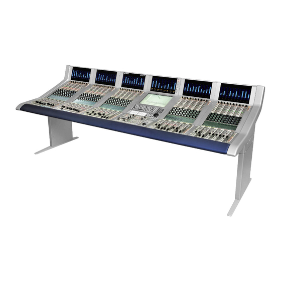
Vista Digital Mixing System VISTA DESK OPERATION Fader Bay 1 Fader Bay 2 Control Bay Fader Bay 3 The desk consists of two types of bays: Up to seven identical fader bays and exactly one control bay. The fader bays contain the console channel strips with rotary controls, faders, keys, and meters. -
Page 40: Fader Bay Overview
Vista Digital Mixing System Fader Bay Overview A fader bay can be subdivided into six areas: • Area [1] contains meters dedicated to each channel strip. • Area [2] contains rotary controls dedicated to each channel strip. This rotary control can have one out of six functions, assigned by the at- tached viewing keys. -
Page 41: Fader Bay Details
Note: It is possible to use the red LED above the meters to indicate headroom rather than clipping. This is set in the GC’s “Meter/Generator ” window. Vista 6: If the channel is an N–1 owner, the right-hand bargraph shows the output signal level. If stereo signals are present, the meter indicates the larger level of the two channels. -
Page 42: Area 3A - Channel Control
Vista Digital Mixing System 2.2.3 Area 3a – Channel Control [10] ¹ IN1 ¹ IN2 ¹ GEN Input Selector. Each channel has three patch points available (the patch is viewable on the Graphic Controller TFT screen, chapter 2.4.3). Input 3 is patched to the internal generator's output by default, but can be changed by the user at any time. - Page 43 Note: In the signaling setup on the Graphic Controller, this key is referred to as “User 1”. Vista 6: METER, toggles the meter tap point between input, post fader, or direct output. Desk Operation 2-7 Date printed: 05.08.03...
-
Page 44: Area 3B - Faders
Fully lit: MUTE is being recorded Upon press: Punch-in/out of MUTE. Vista 6: TALK key, activates talkback to the direct output of this channel and, if applicable, to the n–1 bus output. [26] ¹ l Punch-In/Out of Fader (Dynamic Automation) -
Page 45: Area 4 - Vistonics
• Numerical indication of the current peak meter value if metering is in PEAK: HOLD CONT mode, or of the overload value if OVERLOAD: HOLD is active. • Vista 6: N–1 indication and bus number. Touching the upper half (for input channels, multi-track input channels, [31] multi-track monitor channels): Opens the GC’s General Patch window,... - Page 46 Vistonics™ rotary control area. The VIEW CHANNEL [33] and VIEW MISC [34] keys form a sort of “center assign panel” function, known from many other consoles, such as the Studer D950 M2. [35] ¹ VIEW: BUS ASN Brings up the bus assign view of one channel, covering the whole touch screen area.
- Page 47 Vista Digital Mixing System [38] ¹ GLOBAL VIEW: A/D CTRL ¹ GLOBAL VIEW: INPUT GAIN ¹ GLOBAL VIEW: OUT? ¹ GLOBAL VIEW: FILTER ¹ GLOBAL VIEW: DLY-INS ¹ GLOBAL VIEW: COMP-LIM ¹ GLOBAL VIEW: EXP-GATE ¹ GLOBAL VIEW: EQ ¹ GLOBAL VIEW: PAN ¹...
-
Page 48: Areas 5A, 5B - Channel Selection
Vista Digital Mixing System 2.2.6 Areas 5a, 5b – Channel Selection [50] ¹ MULTI SEL Used to make multiple selections; acts similar as the “Ctrl” key on a PC keyboard. [51] LINK ALL Links all channels of one type together (“Super Gang”) mainly for setup purposes. -
Page 49: Area 6 - Desk Scrolling
Vista Digital Mixing System 2.2.7 Area 6 – Desk Scrolling [60] SCROLL: LOCK BAY Used to lock the corresponding bay. This prevents this particular bay from global scrolling and view changes. However, even a locked bay can be scrolled when using the scroll keys on this particular bay. Global view changes are also only affecting this particular bay if a GLOBAL VIEW key is pressed on the locked bay. -
Page 50: Control Bay Overview
Area [2] contains the monitor metering with VFD bargraph meters. Please note that Vista 6 is equipped with a gain reduction display or a custom meter bridge. Area [3] is the TFT display with the Graphic Controller (GC) application and a keyboard with numerical keypad. -
Page 51: Control Bay Details
Vista Digital Mixing System Control Bay Details 2.4.1 Area 1 – System Power On/Off [70] SYSTEM: STBY Indicates that AC power is connected to the desk. [71] SYSTEM: ON Indicates that the power for the control system is ok. Pressing STBY and ON simultaneously will switch the system on. For switching the system off, normally the Shutdown command in the win- dows desktop is used. -
Page 52: Areas 1 And 2 - Monitor Metering
Vista Digital Mixing System 2.4.2 Areas 1 and 2 – Monitor Metering OVERLOAD: HOLD [80] Activates the hold function for all overload LEDs in the console. If active, even overloads in sections that are currently not visible are held. Therefore it is pos- sible to scroll through the sections and check if overloads have occurred. -
Page 53: Area 3 - Graphic Controller Screen And Keyboard
Vista Digital Mixing System 2.4.3 Area 3 – Graphic Controller Screen and Keyboard The Graphic Controller TFT screen and the alphanumeric keyboard are used for graphic controller operation, such as setup, project management, backup, patching, etc. See chapter 4 for details. -
Page 54: Area 4 - Machine Control
[94] [99] [98] [90] Jog/Shuttle Wheel Sensitivity adjustable in the “Option – Vista Settings” menu on the Graphic Controller. [91] LOC 1...LOC 4 Dedicated locator keys; pressing one of them will make the machine con- trolled via the 9-pin machine control interface locate to the corresponding TC address, if defined. - Page 55 Vista Digital Mixing System [97] CUE – Show Cue List Opens the cue list on the Graphic Controller. [98] ¹ REW 7 ¹ FWD 8 PLAY4 STOP < Standard transport control keys. FWD 8 and REW 7 can also be activated temporarily (by a long press).
-
Page 56: Area 5 - Monitoring Source Selection
12 sources is selected, the dialog will pop up automatically upon the first key press in order to make a selection with the trackball. Vista 6 has 32 source selectors available, four of them can be used as “sub-selectors” as described above. This results in up to 76 definable sources for monitoring. -
Page 57: Area 6 - Studio Monitoring
Vista Digital Mixing System 2.4.6 Area 6 – Studio Monitoring SELECTOR [120] FOLLOW CR PFL/SOLO Determines whether the studio is fed with: • what is selected on the SOURCE SELECTOR (16 keys [111]), • the same source as the control room, or •... -
Page 58: Area 7 - Control Room Monitoring
Vista Digital Mixing System 2.4.7 Area 7 – Control Room Monitoring MONO [130] LCRS 7.1 / EX Selects the control room monitoring format by mut- ing unused speakers. The “mono” setting will sum the left and right monitor speaker signals. - Page 59 Note: The GC allows level calibration of the different speaker sets as well as trimming the individual speakers. Vista 6 has two additional keys located above the CR INJECT key [138]: ON AIR prohibits activation of potentially dangerous functions, such as Solo in Place or Talk to Masters.
-
Page 60: Area 8 - Option (Spare Keys)
• MAST: direct outputs of all masters • DIR: direct outputs of all input channels • BUS: outputs of all multi-track buses (without faders in between) • STUDIO (Vista 6: talkback to both Studio A and B simultaneously) [150] [154] ¹... - Page 61 Vista Digital Mixing System Talkback and Signaling Block Diagram Studio Ext Location 2 Ext Location 1 Ret 2 Ret 1 (Line level) Ext 2 Ext 1 e.g.Speaker e.g.Intercom Talk to Talk to GPI 2 GPI 1 Studio Monitor (-> to PFL Speaker) (->...
- Page 62 Vista Digital Mixing System Talkback and Signaling Block Diagram Studio A Studio B Ext Location 1 Ext Location 2 Ret 1 Ret 2 (Line level) Ext 1 Ext 2 e. g. Speaker e. g. Intercom e. g. Speaker Talk to...
-
Page 63: Area 10A - Headphones Control
Please note that the patches have to be set correctly by the user. These six keys can be de-activated by checking the corresponding options in the GC’s Vista Settings window. Desk Operation 2-27 Date printed: 05.08.03... -
Page 64: Area 11 - Dynamic Automation / Static Automation
Vista Digital Mixing System 2.4.12 Area 11 – Dynamic Automation / Static Automation Please note that in this paragraph the AutoTouch+ dynamic automation system is touched only briefly for explanation of the keys; refer to chapter 5 for more information. - Page 65 Vista Digital Mixing System Note: None of these settings will influence the recording behavior while an ele- ment is punched-in (e.g. touched and recording). They only affect the automation behavior after the element has been punched-out (e.g. un- touched), and therefore make it stay in record further into the future.
- Page 66 Vista Digital Mixing System [181] [182] [183] [184] [192] STOP FRAME: ON Instead of starting and stopping a mix pass auto- matically by detecting the TC play speed, the user [180] [186] can deactivate this automatism, and start and stop...
- Page 67 Vista Digital Mixing System • WRITE Shows and records values and their movements. Depending on TOUCH RECORD [197] and TOUCH HOLD [198] being on or off, the touched elements will be recorded (TOUCH RECORD on) and stay in record upon releasing the element (TOUCH HOLD on).
-
Page 68: Area 12 - Shortcut Keys For Graphic Controller
Vista Digital Mixing System 2.4.13 Area 12 – Shortcut Keys for Graphic Controller [210] SNAPSHOT 1...4 A snapshot contains all audio settings including patching and labels. These keys allow four snapshots to be stored and recalled without making use of the Graphic Controller screen. -
Page 69: Area 13 - Joysticks
Vista Digital Mixing System 2.4.14 Area 13 – Joysticks [220] Display Displays the inherited label of the channel currently assigned to the Joystick. [221] ô Y axis lock ó X axis lock Lock the Y axis (ô) or X axis (ó) when moving the joystick. -
Page 70: Area 14 - Section Navigator
Vista Digital Mixing System 2.4.15 Area 14 – Section Navigator [230] 1...6 Indication of the current position within all sections. Acts similar to a scroll bar, the same as the section indication LEDs [62]. Pressing one of these keys will navigate the desk to the corresponding section directly. -
Page 71: Clipboard Libraries
Vista Digital Mixing System Clipboard Libraries On the Vista console it is possible to store and load clipboards to/from the hard disk or a CD-R. Clipboard files can contain one or more audio func- tions (e.g. EQ only, Dynamics only, or a combination of EQ and Dynam- ics) from a channel, or even can store complete channel settings. -
Page 72: Clipboard Library Window
Clipboard Library Window The Clipboard Library window is automatically opened whenever a paste function is pending on the Vista console. In order to open the window manually (e.g., to load the console clipboard with a stored value), select the corresponding icon from the toolbar or press the OPTIONS F4 key on the console. -
Page 73: Rename/Delete A Clipboard Library File
Vista Digital Mixing System 5 Click on the 2 (Copy/Paste) button of the desired function in order to activate copying. The button will light, and all possible destination keys on the console surface will be half-lit. Shortcut: A double-click on the clipboard name in the list will activate copying of all contained audio values within that particular file directly. -
Page 74: Storage Format
Vista Digital Mixing System 2.5.7 Storage Format Each clipboard is stored in a file with a extension. Multiple files .cpy .cpy form a library. A file may contain only one audio function (e.g. EQ .cpy settings) or a combination of any audio functions of a channel (e.g. EQ and Dynamics settings). - Page 75 Vista Digital Mixing System CHAPTER 3 Parameter Description ..............................3-3 Introduction ................................3-3 View Change................................3-3 3.2.1 Global View Change............................3-3 3.2.2 Channel-Related View Change .........................3-4 Global Views ................................3-5 3.3.1 Input Parameters ...............................3-5 3.3.2 Pre-Amp Remote Parameters..........................3-7 3.3.3 Direct Output and N–1 Output Parameters .......................3-8 3.3.4...
- Page 76 Vista Digital Mixing System 3-2 Parameters SW V3.3 Date printed: 05.08.03...
-
Page 77: Parameter Description
Vista Digital Mixing System PARAMETER DESCRIPTION Introduction The desk can show different audio controls on the Vistonics TFT displays. The controls differ in type of graphical viewing, shapes, and colors. If re- quired, they are grouped together with frames in order to give the user maximum information without the need to read text on the display. -
Page 78: Channel-Related View Change
Vista Digital Mixing System 3.2.2 Channel-Related View Change The views listed below can be activated in a channel strip. Then the corre- sponding values of this particular channel are shown. • Dynamics (by touching the dynamics curve on the TFT) •... -
Page 79: Global Views
Vista Digital Mixing System Global Views 3.3.1 Input Parameters Press GLOBAL VIEW: INPUT GAIN. For input sources IN 1, IN 2, and GEN (selection with the hardware keys below the channel meters), an input control view is available. The number of functions available on Input or Output channels, as well as on mono or stereo channels, depends on the active configuration. - Page 80 Vista Digital Mixing System Input Parameters for Mono Channels only: PHASE [1] Two positions are provided (select either with the key or the rotary): • NORM/Off, in phase (default setting). • REV/On, out-of-phase. Input Parameters for Mono and Stereo Channels: GAIN [2] Input gain can set in 1 dB steps from –24 dB (attenuation by 24 dB) to...
-
Page 81: Pre-Amp Remote Parameters
Vista Digital Mixing System 3.3.2 Pre-Amp Remote Parameters Press GLOBAL VIEW: A / D CTRL. Various functions of the D19m MP4RC quad mic/line input cards can be remote controlled (refer to chapter 4.4.2.2 for details on how to activate or deactivate pre-amp remote control). -
Page 82: Direct Output And N-1 Output Parameters
Vista Digital Mixing System 3.3.3 Direct Output and N–1 Output Parameters Press GLOBAL VIEW: OUT. This view allows to control the level of the Direct Output and of the N–1 Output, provided that the channel is assigned as a bus owner of an N–1 bus. -
Page 83: Mono Aux Parameters
Vista Digital Mixing System 3.3.4 Mono AUX Parameters Press one of the GLOBAL VIEW: AUX MONO keys. The mono AUX view provides selection of the AUX bus (ON/OFF), send level adjustment, and pre-/after-fader switching. [16] [15] [17] [16] [15] [17]... -
Page 84: Stereo Aux Parameters
Vista Digital Mixing System 3.3.5 Stereo AUX Parameters Press one of the GLOBAL VIEW: AUX STEREO keys. The stereo AUX view provides selection of the AUX bus (ON/OFF), send level adjustment, pre-/after-fader switching, and pan setting. [19] [18] [21] [20]... -
Page 85: Filter Parameters
Vista Digital Mixing System 3.3.6 Filter Parameters Press GLOBAL VIEW: FILTER. This view enables the user to control the parameters of the hi- and low-cut filters. These filters are available on the channel-related EQ view as well, refer to chapter 3.4.1. -
Page 86: Delay And Insert Parameters
Vista Digital Mixing System 3.3.7 Delay and Insert Parameters Press GLOBAL VIEW: DLY-INS. This view enables the user to control the delay and insert parameters. Please note: The two sections are activated with the DELAY and INS hard- ware keys below the channel meters. - Page 87 Vista Digital Mixing System INSERT MIX On/Off [24] On activates the insert mix function; off selects only the insert return sig- nal. When the insert mix function is set to ON, the ratio of the dry (send) to the wet (return) signal depends on the selected mix ratio. In other words, mixing between the insert send and the insert return signals is possible.
-
Page 88: Compressor/Limiter Parameters
Vista Digital Mixing System 3.3.8 Compressor/Limiter Parameters Press GLOBAL VIEW: COMP-LIM. This view enables the user to control the most important parameters of the dynamics section’s compressor and limiter parts. The complete parameter set is available on the channel-related dynamics view, refer to chapter 3.4.2. -
Page 89: Expander/Gate Parameters
Vista Digital Mixing System 3.3.9 Expander/Gate Parameters Press GLOBAL VIEW: EXP-GATE. This view enables the user to control the most important parameters of the dynamics section’s expander and gate parts. The complete parameter set is available on the channel-related dynamics view, refer to chapter 3.4.2. -
Page 90: Eq Parameters
Vista Digital Mixing System 3.3.10 EQ Parameters There are two views enabling the user to control the most important pa- rameters of the EQ section. The standard view (on the left, showing the gain values of all four bands) is activated by just pressing GLOBAL VIEW: EQ;... -
Page 91: Panning Parameters
Vista Digital Mixing System 3.3.11 Panning Parameters Press GLOBAL VIEW: PAN. This view enables the user to control the most important parameters of the panning section. Representation is different depending on channel type (mono or stereo), and on the selected panning format. The complete pa-... -
Page 92: Global Bus Assignment View
Vista Digital Mixing System 3.3.12 Global Bus Assignment View Press GLOBAL VIEW: BUS ASN (at the left-hand side of the fader bay). This is an On/Off key that can be activated in addition to other global view keys. The bus assignment overview will cover the EQ, dynamics and pan curves on the lower part of the TFT;... -
Page 93: Generic And Label Display Area
Vista Digital Mixing System 3.3.13 Generic and Label Display Area Channel label display: The top line always indicates the inherited label (corresponds to the user label of the patched source – “track sheet”) of each channel. The second line normally is set to user label display, but can be changed by pressing GLOBAL VIEW: LABEL TYPE. -
Page 94: Channel-Related Views
Vista Digital Mixing System Channel-Related Views 3.4.1 EQ / Filter Parameters [27] [32] [28] [30] [26] [29] [31] [27] [34] [28] [30] [26] [29] [33] [27] [28] [30] [26] [29] [35] [27] [32] [28] [30] [26] [29] [31] EQ Parameters: HI/HM/LM/LO On/Off [26] On/off function for the selected EQ band. - Page 95 Vista Digital Mixing System Frequency [32] Cutoff frequency adjustment for the high- and low-cut filter: 20 Hz through 20 kHz, in 120 steps. Notch Filter Parameters: Please note that these two fields only appear if the notch filter is config- ured (i.e., “EQ with Notch”...
-
Page 96: Dynamics Parameters
Vista Digital Mixing System 3.4.2 Dynamics Parameters [37] [63] [38] [40] [60] [39] [61] [36] [62] [42] [65] [43] [45] [46] [44] [41] [64] [48] [67] [49] [51] [52] [47] [50] [66] [54] [63] [55] [57] [59] [53] [56] [58]... - Page 97 Vista Digital Mixing System Compressor Parameters: CMP On/Off [41] Compressor on/off. CMP THRS [42] The compressor threshold level can be adjusted in 1 dB steps from 0 dB to –96 dB CMP REL [43] The compressor release time can be adjusted in 13 steps within a 10 ms to 10 s range (10 ms, 20 ms, 30 ms, 50 ms, 100 ms, 200 ms, 300 ms, 500 ms, 1 s, 2 s, 3 s, 5 s, and 10 s).
- Page 98 Vista Digital Mixing System Gate Parameters: GATE On/Off [53] Gate on/off. GATE THRS [54] The gate threshold level can be adjusted in 1 dB steps from 0 dB –96 dB GATE REL [55] The gate release time can be adjusted in 13 steps within a 10 ms through 10 s range (10 ms, 20 ms, 30 ms, 50 ms, 100 ms, 200 ms, 300 ms, 500 ms, 1 s, 2 s, 3 s, 5 s, and 10 s).
- Page 99 Vista Digital Mixing System SC HI CUT/LO CUT [63] Both side-chain filters feature cut-off frequencies continuously adjustable between 20 Hz and 20 kHz. MKUP auto on/off [64] Auto Make-up Gain function on/off. MKUP GAIN [65] For manual gain compensation; gain can be set in 1 dB steps from 0 through +24 dB.
-
Page 100: Panning Parameters
Direction and Direction with Width func- tions are available for stereo input and group channels. The panning functions can be controlled by the Vista 7’s motorized joy- sticks. To assign a channel to a joystick, press the joystick FOLLOW key (it will light) and then the LINK/SEL key for the desired channel. - Page 101 Vista Digital Mixing System LR PAN for Stereo Channels The functions PAN ON/OFF and PAN have been extended to enable working with either standard (L/R) stereo or with MS (mono/side) signals. In addition, features are available to increase the stereo image manipula- tion possibilities, such as •...
-
Page 102: Amplitude Panning Parameters
Vista Digital Mixing System 3.4.3.1 Amplitude Panning Parameters Mono Channels: Stereo Channels: [69] [71] [70] [74] [73] [68] [72] LR Panning Parameters for Mono Channels: Mono channel LR PAN has only one panning function: left/right panning. It is useful for left/right panning to stereo master or group buses, or for odd/even panning to group or multi-track buses. - Page 103 Vista Digital Mixing System from 0 to –∞ dB while the left channel remains at full input level, and vice versa. The INP DIR function is used to control the direction of a stereo input signal. Turning the rotary encoder shifts the input direction in 1° steps from –30°...
-
Page 104: Multi-Format Panning Parameters
Vista Digital Mixing System 3.4.3.2 Multi-Format Panning Parameters Surround panning consists of two panning algorithms: Multi-format pan- ning, and VSP (Virtual Surround Panning). These support a variety of sur- round formats and applications; in all these modes, an LFE (Low Fre- quency Effects) control is available. - Page 105 Vista Digital Mixing System LFE LEVEL [82] LFE level control from MUTE (i.e. –∞ dB) to +10 dB. Within this section, no filtering is applied to the signal fed to the LFE bus. PANARND On/Off [83] This key activates the unique Pan-Around function...
-
Page 106: Vsp Panning Parameters
Vista Digital Mixing System 3.4.3.3 VSP Panning Parameters Please note that items [75] through [86] (i.e., the left part of the graphic below) are identical with the ones in chapter 3.4.3.2 – for details, please refer to the description in that chapter. - Page 107 Vista Digital Mixing System source. This mode is only useful in two-channel mode, and presents a very accurate sound field. • HRTF – Mainly a cross-talk canceler using simplified HRTFs (Head Related Transfer Functions). If the listener is positioned exactly in the sweet spot of a ±30°...
- Page 108 Vista Digital Mixing System FOCUS [95] Focus controls the gains of the reflections depending on their distribution in time. A high focus (+12 dB) boosts the early discrete reflections which are located around the originating source (like on a stage) and creates a fo- cusing effect.
-
Page 109: Reverb Channel Parameters
Vista Digital Mixing System 3.4.4 Reverb Channel Parameters For additional information on reverb channels, please refer to chapter 3.6. [98] [101] [97] [100] [99] [102] OUT On/Off [97] Muting the audio will immediately cut the reverb signal with no reverb tail hanging over. -
Page 110: View Channel
Vista Digital Mixing System 3.4.5 View Channel Pressing VIEW: CHANNEL brings up an overview of the channel, covering the whole Vistonics TFT. All available parameters are shown in the rotary section, except for dynamics, EQ, and panning (see chapter 3.4.6). Only available parameters are visible. -
Page 111: View Bus Assignment
Vista Digital Mixing System 3.4.7 View Bus Assignment When touching any of the variable areas, the display changes to the bus assign window of this particular channel, as if the corresponding VIEW: BUS ASN hardware key underneath the TFT would have been pressed. -
Page 112: Views In Automation Mode
Vista Digital Mixing System Views in Automation Mode In automation mode, the channel strips hold additional indications for de- tailed display of the current status. This chapter shows all possible indications of automation status and ex- plains their meaning. First, there are some record indicators integrated within the recording keys: Recording overview for switches. - Page 113 Vista Digital Mixing System The meaning of the different Vistonics indicators is as follows: Displayed Value The displayed value (e.g. “–7.6 dB) is always the current value, except when the control is in TRIM mode. Then it shows the offset from the TRIM null point.
- Page 114 Vista Digital Mixing System Recording Recording mode of the fader (in the Vistonics generic display area): Characters without a frame indicate the status of the fader (I = Isolate, R = Read, T = Trim, W = Write). A red frame behind the “W” or “T” indicates that the fader is currently recording.
-
Page 115: 3.6 Vsp Quick Operating Guide
Vista Digital Mixing System 3.6 VSP Quick Operating Guide With the release of the V2.5 software for the D950/Vista mixing consoles, Studer has also created an enhanced version of its proprietary room mod- eling software called VSP (= Virtual Surround Panning). VSP is unique in that it can truly produce acoustic scenes that emulate real-world room spaces within an audio console. - Page 116 This is what the listener hears in a room: Late Reflections Sound Source Early Reflections Direct Sound Late Reflections Room ... and Studer’s VSP generates signals from the five speakers that simulate the same listening experience: Late Reflections (Virtual) Sound Source Early Reflections Direct Sound...
-
Page 117: Two Vsp Operating Styles
PAN to the rotaries. In Page 1, the display at the bottom will read VSP (as opposed to a Multi-Format panner which will display MPAN). For Vista users, a small VSP logo is shown in the pan view (in the Viston- ics touch area). -
Page 118: Vsp Channel Controls
Vista Digital Mixing System ent acoustic scenes (sound spaces), multiple reverb channels can also be used. To summarize this operating style: It uses one or more VSP channels and typically one Reverb channel for each acoustic space that is required. - Page 119 Vista Digital Mixing System • User – When this mode is selected, the panning algorithms are estab- lished from the Microphone User Settings interface provided under the main Option menu in the system Graphic Controller. The settings made affect the relationship between amplitude and time differences, deter- mined by the settings of the imaginary microphones.
-
Page 120: Reverb Channel Controls
Vista Digital Mixing System Note: To disable the VSP panner and use a VSP Channel as a conventional pan- ner, just set the Ambience (AMBI) switch to OFF, and Panner mode (Pmod) control to Amplitude. The panner will now function as a standard Multi-Format panner. -
Page 121: Operating In Full Vsp Style
Vista Digital Mixing System 3.6.5 Operating in Full VSP Style As previously described, in VSP Style of operation (chapter 3.6.2), several sound sources are brought into VSP Input channels. One or more Reverb Channels may be set up. Each VSP channel may feed one (or more, only for special effects) Reverb channels. -
Page 122: Operating In Reverb-Only Style
Vista Digital Mixing System 3.6.6 Operating in Reverb-Only Style As previously described, in the Reverb Style of operation (chapter 3.6.2), the sound sources are brought into normal Input channels. One or more Reverb Channels can be set up, each one with a corresponding VSP chan- nel. -
Page 123: Microphone Simulation Tool (Mst) - User Pan Mode
Vista Digital Mixing System 3.6.7 Microphone Simulation Tool (MST) – User Pan Mode As a further sophistication of the VSP system, a new Microphone Simula- tion Tool (MST) has been created. This allows the mix engineer to create his/her own multichannel panning law, by simulating the placement of mi- crophones in a virtual space. - Page 124 Vista Digital Mixing System Here are the placements for some of the Panner Mode presets: ORTF (With Surrounds) Amplitude varies due to the directionality of the microphones, while time delay is varied based on the distances between the microphones (which each feed a speaker).
- Page 125 This is an exciting and functional tool that the mix engineer now has exclusively with the use of the VSP panning system within the Studer D950 or Vista consoles.
-
Page 126: 3.7 Input Channel Block Diagrams
Vista Digital Mixing System 3.7 Input Channel Block Diagrams Block Diagram of a Typical Mono Input Channel: Please note that, essentially, all channel types have the same structure, regardless of the type (input, AUX, group, master, etc.) 3-52 Parameters SW V3.3... - Page 127 Vista Digital Mixing System 3.8 Input Channel Block Diagrams Block Diagram of a Typical Stereo Input Channel: Please note that, essentially, all channel types have the same structure, regardless of the type (input, AUX, group, master, etc.) Parameters 3-53 Date printed: 05.08.03...
- Page 128 Vista Digital Mixing System 3-54 Parameters SW V3.3 Date printed: 05.08.03...
- Page 129 Setup & Activate the Dynamics Sidechain Link ..................4-42 4.4.4 Snapshot Page ..............................4-44 4.4.4.1 Snapshots ..............................4-45 4.4.4.2 Snapshot Crossfading..........................4-48 4.4.4.3 Additional Snapshot Functionality for Vista....................4-49 4.4.4.4 Partial Snapshots............................4-51 4.4.4.5 Snapshot Filtering (Static Automation).......................4-52 4.4.4.6 Correcting the Mask of a Partial Snapshot....................4-55 4.4.4.7 Typical Application Examples........................4-56...
- Page 130 4.4.7 Vista Strip Setup............................. 4-68 4.4.7.1 How to Use Vista Strip Setup........................4-70 4.4.7.1.1 Assigning a Single DSP Channel to a Single Channel Strip..............4-70 4.4.7.1.2 Assigning Multiple Channels in one Single Action ................4-70 4.4.7.1.3 Moving Already Assigned DSP Channels to Other Channel Strips............4-71 4.4.7.1.4 Useful Information ..........................
- Page 131 D950/Vista Digital Mixing System Fourth Level of Operation: SysAdmin Menu......................4-109 4.7.1 SysAdmin: General Patch/Subclassifying the Digital I/O Sections...............4-110 4.7.1.1 Setting the Subclass Labels........................4-111 4.7.1.2 Assigning Sources and Targets to Subclasses ...................4-112 4.7.2 SysAdmin: Surveyor .............................4-114 4.7.3 SysAdmin: Show VMC Tree ........................4-114 4.7.4...
- Page 132 D950/Vista Digital Mixing System 4-4 GC Operation SW V3.3 Date printed: 05.08.03...
-
Page 133: Graphic Controller Operation
The D950/Vista System software may also be started from the Windows Start menu (if programmed). All the D950 or Vista software runs under Windows NT or Windows 2000 operating system, respectively. All files used by the D950/Vista and all the files produced by the user (snapshots, mixes, etc.) are fully compatible... - Page 134 D950/Vista Digital Mixing System ble-click techniques. The Tab, PgUp/Dn, and arrow keys behave according to standard Windows operations. The Graphic Controller’s screen colors, screen sizes, individual window positions and sizes, certain font sizes etc., are also part of the Windows Screen Properties, and can be adjusted there.
-
Page 135: The Gc Screen
D950/Vista Digital Mixing System The GC Screen Upon starting the GC for the first time, the screen will look something like this: Main window Title bar Menu bar Toolbar Workspace controls Status bar GC Operation 4-7 Date printed: 05.08.03 SW V3.3... - Page 136 Workspace controls Status bar Please note the most important parts of the screen: • The Menu Bar, allowing access to all the D950/Vista’s functions. Refer to chapter 4.6; • The Toolbar, containing various short-cut icons for the most important functions;...
-
Page 137: The Toolbar
D950/Vista Digital Mixing System 4.2.1 The Toolbar The toolbar contains a number of short-cut icons for the D950/Vista’s most important functions. There are four (or five) individual parts of the toolbar: Page Selection, Channel Selection, Tools, System Functions (and Multidesk Groups, if configured). -
Page 138: The Status Bar
Short on-line help information. Status information is displayed in the Status Bar continually. It is espe- cially helpful to view the Status Bar during startup of the D950/Vista sys- tem, because various information regarding the boot process and system parts will be displayed on the monitor screen. -
Page 139: Graphic Controller Basics
Controller (GC). 4.3.1 Sources and Targets Generally, all audio signals available to the D950/Vista can be divided into Sources and Targets. These names are used rather than “Input”, “Output”, etc., in order to avoid any confusion regarding where the audio signal comes from, and to where it goes. -
Page 140: The Session Configuration
We often refer to the Virtual Mixing Console (VMC) when speaking about the Session Configuration. VMC is another concept that forms the very foundation of a D950/Vista: all functions and the current Session Configu- ration data are stored within the VMC. A simplified definition of the VMC ”The VMC is a data structure containing descriptions of the console’s... -
Page 141: Labels
D950/Vista Digital Mixing System 4.3.3 Labels Labels are used extensively within the system to define objects, such as audio sources, channel names, etc., and to visualize these objects in vari- ous windows within the GC. Please note that all labels are stored within Snapshots and Presets, together with all audio settings. -
Page 142: First Level Of Operation: Main Gc
D950/Vista Digital Mixing System First Level of Operation: Main GC Pages There are five main Graphic Controller pages, each of which deals with a different operating part of the D950/Vista System: • General Patch Page • Channel Patch Page •... -
Page 143: One Page, Or More
D950/Vista Digital Mixing System 4.4.1 One Page, or More... The GC Workspace can be used to display one single page, or a number of pages and panels at the same time. Because different users will prefer dif- ferent page layouts, the User Menu enables Workspace layouts to be stored and retrieved for later use by any number of users. -
Page 144: Working With Multiple Pages
D950/Vista Digital Mixing System 4.4.1.2 Working with Multiple Pages A number of different pages can be opened on the screen at the same time, and drag-and-drop techniques used to position and size the selected pages. F Tip To open more than one page, open the first page using the methods listed above;... - Page 145 D950/Vista Digital Mixing System You can also open the same page more than once, which can be useful for simultaneously viewing different areas of the General Patch page, for ex- ample. The page you used last will be selected, which is indicated by highlighting the Title bar in blue.
-
Page 146: The General Patch
From the Page menu, by clicking on the appropriate menu item • Using the Page icons, by clicking on the appropriate icon in the tool- Using the GENERAL PATCH (D950) or GLOBAL PATCH (Vista) func- • tion key. This is the fastest way. -
Page 147: General Patch Navigation
D950/Vista Digital Mixing System • Source and Target drop-down menus for selection of the subcategory to be viewed • Auto Select function • Viewing selections which allow sorting of the Sources and Targets Lists by label type • The Fixed/User Label displays for the selected Source/Target (refer to chapter 4.3.3). - Page 148 D950/Vista Digital Mixing System 4-20 GC Operation SW V3.3 Date printed: 05.08.03...
-
Page 149: Other Navigation Methods
D950/Vista Digital Mixing System 4.4.2.1.2 Other Navigation Methods Choosing Source/Target Subcategory: There are two methods to select the required Source/Target subcategory: Use the Source/Target subcategory drop-down menu. Right-click directly in the Sources/Targets List. All the available sub- categories (identical to those in the drop-down menus) can be ac- cessed directly from the lower portion of the menu. -
Page 150: What Subcategories Are There
Sends from the inserts of all channel types. Bus Out: Unlike analog consoles, with the D950/Vista any bus is a valid audio sig- nal source; AUX Mono Bus 12 can be used to feed an output interface, or to become an input to an input channel. -
Page 151: How To Deal With The Analog Interfacing
“Where are the analog interfaces coming in?”, you might be asking. We still need some analog sound. Here is how we achieve that task: The D950/Vista Patch and DSP systems only know about digital interfac- ing, as can be seen from the following simplified block diagram:... - Page 152 D950/Vista Digital Mixing System As soon as both cross-points have been made, the MIC CTL LED on the corresponding console Channel Strip will be lit to indicate an established connection (assuming the corresponding channel input has been selected). F Tip Even if it appears complicated, this procedure really is quite simple.
-
Page 153: Digital Input/Output Subclasses
D950/Vista Digital Mixing System 4.4.2.3 Digital Input/Output Subclasses The two subcategories “Digital In” (Sources) and “Digital Out” (Targets) show the list of available physical inputs and outputs of the loaded Session Configuration. These sources and targets provide all the interfacing of the console to the outside world. -
Page 154: Making And Clearing The Cross-Points
D950/Vista Digital Mixing System 4.4.2.4 Making and Clearing the Cross-Points The creation and updating of cross-points is simple. First, select the Source and Target; the Selection Bars have to be crossed to form an X-Y pair. There are two ways of making or breaking a cross-point connection: •... - Page 155 D950/Vista Digital Mixing System Stereo Source – Mono Target: Icon Indicates Type of Connection Left to Mono Right to Mono Clear Protected Connection Mono Source – Stereo Target: Icon Indicates Type of Connection Mono to Both L & R Mono to L, Leave R as is...
- Page 156 D950/Vista Digital Mixing System F Tip A feature is available for fast diagonal patching of multiple Sources to multiple Targets. The example below shows this feature used in practice. Example: Patching the first 16 Mic inputs to the first 16 Mono Input Channels.
-
Page 157: Editing The User Labels In The General Patch
D950/Vista Digital Mixing System 4.4.2.5 Editing the User Labels in the General Patch To edit the User Labels in the General Patch, first click on the desired Source/Target in the Sources/Targets list. The User Label and Fixed Label for the chosen Source/Target will be shown in the Label Fields at the bot- tom of the screen: Click on the User Label Field of the Source/Target. -
Page 158: Sorting Options
Clicking this button will toggle the label view globally throughout all parts of the GC (D950 and Vista) and channel strip display (D950 only). The la- bel display can be toggled between “User”, “Inherited” and “Fixed”. For a detailed description of how to work best with labels, see below. -
Page 159: Working With Labels
D950/Vista Digital Mixing System 4.4.2.6 Working with Labels For a detailed description of different label types, please refer to chapter 4.3.3. The most important aspect of any audio patching system is its labeling. Clear labeling allows fast navigation and fault-free patching. -
Page 160: Method 1: Analog-Style
Vista, some typographic issues may come up when looking at the label display on a Vista desk. This is the reason why we rec- ommend not to work with this method on a Vista console. - Page 161 D950/Vista Digital Mixing System This means that the User Labels will be shown in all GC windows. On the channel strip displays, the User Label of the Channel Patch will be shown. To see which Source is routed to the channels on the channel strips, switch the label mode to “Show Inherited Labels”.
-
Page 162: Method 2: Automatic Label Propagation
D950/Vista Digital Mixing System 4.4.2.6.2 Method 2: Automatic Label Propagation This is the typical way the users will work on a Vista console, but it can be applied to the D950 as well. D950: You type all your labels in the patch and let the system propagate them automatically to the connected channels. - Page 163 D950/Vista Digital Mixing System Change View by Clicking on Label Type Button in the GC's Toolbar ( Sources ) General Patch e.g. e.g. e.g. AES #1 Vocal Track 1 (Targets) Vocal Displays e.g.: Track 1 How to Proceed: • Switch on the “Use Device Labels” option in the SysAdmin/Device Labels menu.
-
Page 164: What Are Device Labels
D950/Vista Digital Mixing System Note: In the Strip Setup window it is possible to display either the session labels (standard) or the device labels, depending on the option indicated in the lower right corner of the window. Show Inherited Labels 4.4.2.7... -
Page 165: Where Are The Device Labels Stored
D950/Vista Digital Mixing System 4.4.2.9 Where are the Device Labels Stored? As you know, these labels are normally not changed for a specific session, but will stay constant in a studio installation. This is why they are stored in a preset ( ) file, being valid for a whole session configuration, rather *.pre... -
Page 166: Channel Patch
As its name implies, the Channel Patch is channel-oriented, which means that only one channel is displayed at a time. To select a channel to be displayed in the Channel Patch page: Press the SEL key (LINK/SEL key for Vista) on the desired Desk Chan- • nel Strip, or •... -
Page 167: Using The Channel Patch For Patching Audio
D950/Vista Digital Mixing System If using the SEL key on the Desk, make sure that the Follow Desk icon F Tip in the toolbar (refer to chapter 4.2.1) is not crossed out. If it is crossed out, click it once to establish Follow Desk selection mode. -
Page 168: Setting The Order Of Dsp Processing Blocks
D950/Vista Digital Mixing System F Tip To quickly toggle the display from Channel Patch to General Patch page, just click the right trackball button while the cursor is positioned anywhere in the Channel Patch page. To quickly switch back from General Patch to Channel Patch page, just click the right trackball button while the cursor is positioned over the X-Y field in the General Patch. -
Page 169: Set The Metering And Direct Out Source Point
D950/Vista Digital Mixing System 4.4.3.5 Set the Metering and Direct Out Source Point Set Metering Source Point: To set the Metering Source point in the selected channel’s audio path, click on one of the three Meter boxes. The channel meter will now be sourced from the selected point in the signal path. -
Page 170: Setup & Activate The Dynamics Sidechain Link
Group. The channel must be assigned to a Link Group in order for the En- able Sidechain Link box to function. The SCL (Sidechain Link) keys on the LACP (D950) or Vistonics (Vista) will follow the selections. The status of the Sidechain Link is stored within Snapshots and Presets. - Page 171 Selected Sidechain Link Select Available Channels The D950S/Vista is able to link together more than two side chains – in fact up to eight per Sidechain Link. For these reasons, a number of Side- chain Links (each for up to eight member channels) has to be specified during setting up of the Session Configuration.
-
Page 172: Snapshot Page
Presets from other titles and configurations, refer to chapter 4.6.1.4. Because it is possible to store an unlimited number of Snapshots, D950/Vista operators will probably find themselves using them more and more every day. A Snapshot or Preset will store: •... -
Page 173: Snapshots
D950/Vista Digital Mixing System 4.4.4.1 Snapshots To capture a new Snapshot of the various user controls, press the MAKE SNAP key (D950) or MAKE SNAPSHOT key (Vista) on the console: Vista: D950: The new Snapshot will automatically be numbered something like etc. - Page 174 D950/Vista Digital Mixing System Now You Can: Recall a Snapshot • Select a Snapshot from the List, and • Click on the Recall button, or • Simply double-click on the Snapshot you wish to recall. Clicking on the Next button will recall the currently selected snapshot and automatically move one line down within the Snapshot list and recall the next Snapshot.
- Page 175 D950/Vista Digital Mixing System Update a Snapshot • Select a Snapshot from the List, and • Click on the Update button. This action will bring up a window that allows the user to confirm the update. An update will store any changes you since made under the se- lected Snapshot’s name.
-
Page 176: Snapshot Crossfading
The Snapshot crossfading may be deactivated by deselecting the Xfade Active option on the Snapshot Screen. On Vista 7, this can also be done by pressing the GLIDE key on the AUTOMATION panel in the Control Bay. -
Page 177: Additional Snapshot Functionality For Vista
D950/Vista Digital Mixing System 4.4.4.3 Additional Snapshot Functionality for Vista In addition to the dedicated MAKE SNAPSHOT hardware key on the Vista surface, there are four SNAPSHOT 1...4 keys for storing and recalling four individual snapshots on these keys. 4 dedicated keys... - Page 178 D950/Vista Digital Mixing System Snapshot Preview: By clicking on the PREVIEW button, the console enters this mode. Whichever Snapshot the user selects, pink elements within all Vistonics™ elements will show any difference between the current console settings and the settings within the previewed Snapshot. It is still possible to recall any Snapshot by all mechanisms described above.
-
Page 179: Partial Snapshots
D950/Vista Digital Mixing System 4.4.4.4 Partial Snapshots It is possible to create snapshots that do not affect the whole console when recalled. They are called “partial snapshots”. When recalling such a snap- shot, only some of the channels – or even only some of their elements – are being changed on the desk. -
Page 180: Snapshot Filtering (Static Automation)
Entering Edit Filter Mode When you click the Edit Snapshot Filter button in the toolbar or press the LOCAL / EDIT keys on the Vista’s control bay Automation panel, you will put the whole console into edit snapshot filter mode. Exit by click- ing/pressing the same button or key again. - Page 181 D950/Vista Digital Mixing System Adding a Whole Bus to the Snapshot Filter In edit snapshot filter mode (as described above), the following window is shown on the GC screen: This window allows adding a whole group of parameters to your snapshot filter.
- Page 182 D950/Vista Digital Mixing System Caution: Clicking on the “Clear All” button will completely remove the snapshot filter and therefore may change all console parameters upon the next snap- shot recall. Clicking on the “Mask All” button will protect the whole console (with some exceptions, such as Patch points) against snapshot recalls, afterwards allowing to enable just single elements to be activated.
-
Page 183: Correcting The Mask Of A Partial Snapshot
D950/Vista Digital Mixing System 4.4.4.6 Correcting the Mask of a Partial Snapshot If a partial snapshot already has been made and the user finds that he for- got to have some channels in that snapshot, there is a powerful method to correct the mask contained in a partial snapshot. -
Page 184: Typical Application Examples
Isolate just the EQ of one or more channels from being changed by upcoming snapshot recalls (Vista only): Press and hold AUTO MODE in order to enter the edit snapshot filter mode, indicated by magenta-colored frames within all Vistonics™... -
Page 185: Default Settings
D950/Vista Digital Mixing System 4.4.4.9 Default Settings In the Preset List, there is always one line labeled defaultSettings. This is a Preset that is automatically generated for every Session Configu- ration, but no file will be found in the corresponding Session Configura- tion directory (as would be the case for other Presets). -
Page 186: Cue List Page
Automation and the TC2 or TC3 time code options are installed on your D950/Vista. The Cue List helps to deal with parts of a musical piece or film you want to keep track of in time. That could be an Intro, Chorus A, Bridge, Chorus B, the End of a song, or a scene from the film you might want to (auto-) locate to. - Page 187 D950/Vista Digital Mixing System Capture: To quickly make a Cue and edit the name and/or timecode stamp later (if necessary), press CAPT CUE on the console when you hear the audio event to be marked: D950: Vista: It is also possible to use the Capture button in the Cue List.
- Page 188 D950/Vista Digital Mixing System Make: To make a Cue means: • First enter a name within the edit window that appears when you click the Make button • Wait for the right audio event to occur, and click the on-screen OK...
- Page 189 D950/Vista Digital Mixing System Info: Calls up Cue Info: Click on the Info button, an action that will bring up a window displaying • Cue List name; • Cue List creation date and time; • Cue List last modification date and time.
-
Page 190: D950 Strip Setup
D950/Vista Digital Mixing System 4.4.6 D950 Strip Setup (for Vista Strip Setup, refer to chapter 4.4.7) The Strip Setup page of the Graphic Controller can be called up in three different ways: • From the Page menu, by clicking on the appropriate menu item;... -
Page 191: Background Of The D950 Strip Setup Principle
D950/Vista Digital Mixing System 4.4.6.1 Background of the D950 Strip Setup Principle Because the D950 User Interface Desk is fully assignable, any DSP chan- nel can be assigned to any Channel Strip at any time. In fact, the same channel may be assigned to multiple desk locations (while it may be con- trolled from many locations, there is only one audio path). - Page 192 D950/Vista Digital Mixing System The following is an example of the ways in which a D950 Desk with 16 Channel Strips may be assigned for two very different Session Configura- tions: Example #1: Bank 1 Layer 1 In Mono 1 In Mono 2 In Mono 3 In Mono 4 In Mono 5 In Mono 6 In Mono 7 In Mono 8 In Mono 9 In Mono 10 In Mono 11 In Mono 12 Master 1...
-
Page 193: How To Use D950 Strip Setup
D950/Vista Digital Mixing System 4.4.6.2 How to Use D950 Strip Setup To create a new Strip Setup or to adapt an existing Strip Setup – regardless whether it belongs to a new Title, or has already been edited – first call up the Strip Setup page. - Page 194 D950/Vista Digital Mixing System You can also select “empty” if you do not wish to assign a channel to a particular Strip. Multiple Channel Strips can be selected in several ways: • By double-clicking on any Strip will select the entire Layer;...
- Page 195 D950/Vista Digital Mixing System So, after you have edited it, the Session Configuration from Example #2 (above) may be laid out in a different way: Bank 1 Layer 1 AUX 1 AUX 2 In Mono 1 In Mono 2 In Mono 3 In Mono 4 In Mono 5 In Mono 6 In Mono 7 In Mono 8 Master 1...
-
Page 196: Vista Strip Setup
• From the Page menu • Using the Page Icons Using the STRIP SETUP function key in the Control Bay of the Vista • surface. The Strip Setup page has a number of functions. Primarily, the “Strip Setup” window allows the user to assign DSP Channels onto the Vista sur- face. - Page 197 D950/Vista Digital Mixing System Color is also used to aid the user in channel identification. The colors re- late to the channel type being shown and these are consistent with the use of color for channel identification on the screens of the fader bays.
-
Page 198: How To Use Vista Strip Setup
D950/Vista Digital Mixing System 4.4.7.1 How to Use Vista Strip Setup To create a new strip setup or to adapt an existing strip setup, first call up the strip setup page (see above). 4.4.7.1.1 Assigning a Single DSP Channel to a Single Channel Strip To assign a channel to one of the virtual channel strips, right-click on the virtual channel strip that the DSP channel is to be displayed on. -
Page 199: Moving Already Assigned Dsp Channels To Other Channel Strips
D950/Vista Digital Mixing System 4.4.7.1.3 Moving Already Assigned DSP Channels to Other Channel Strips If a DSP channel is already assigned to a channel strip, it is extremely easy to change the channel strip on which it is shown. Simply click-and-hold the left trackball button on the desired channel and drag-and-drop it onto any other channel strip. -
Page 200: Useful Information
See chapter 4.4.2.6 for more information regarding the Vista labeling system. For this reason, a checkbox is provided which locks the label type view of Strip Setup to show the “Inherited labels” (see below). Check the “Show Inher- ited Labels”... -
Page 201: Meters
D950/Vista Digital Mixing System 4.4.7.1.6 Meters The Strip Setup page provides an excellent overview of the meter activity of the channels on the virtual console. Every channel displayed on the virtual console surface has a slow meter which is a slow indication of signal activity at this channel’s input. Fur- thermore, by use of color the user can identify whether the channel fader is open and whether the channel is switched on. -
Page 202: Second Level Of Operation: The Toolbar Functions
D950/Vista Digital Mixing System Second Level of Operation: The Toolbar Functions The toolbar contains a number of short-cut icons for the most important D950/Vista system functions. There are four (or five) individual parts of the toolbar: • Page Selection •... -
Page 203: Tools
D950/Vista Digital Mixing System 4.5.2 Tools The various control panels from the Tools section of the toolbar can be called up or hidden in three different ways: • Via the View menu; • Using the toolbar icons, by clicking on the appropriate icon;... -
Page 204: Tools: Machine Control Window
The Machine Control window allows simple machine control functions to be operated from the GC screen. The basic machine control functions are also available from the Control Surface panel (except for Vista 6). The Machine Control window is always positioned on the top level of display of the windows of the GC. -
Page 205: Machine/Tc Generator Control
The feature has been tested with common Sony VCR machines. Studer cannot guarantee proper function with all 9-pin machines being currently on the market. However, some options exist for system administrator use to adapt the 9-pin behavior of the D950/Vista to some machines (refer to Service Manual). -
Page 206: Tools: Title Memo
D950/Vista Digital Mixing System 4.5.2.2 Tools: Title Memo The Title Memo editor page allows any relevant Title information to be kept for later use. There is one Memo per Title. Its contents can include Studio name, Producer Name, Engineer Name, Artist Name, plus a free- form Memo pad. -
Page 207: Channel Selection Tool
D950/Vista Digital Mixing System 4.5.3 Channel Selection Tool This tool allows one console Channel to be selected for control of various centralized functions on the Graphic Controller, such as Channel Patch. There are three arrow buttons: Selects the previous channel from the list;... -
Page 208: System Functions
D950/Vista Digital Mixing System 4.5.4 System Functions 4.5.4.1 System Functions: Protect/Unprotect SysAdmin Mode This action allows the system user mode to be toggled from Standard to System Administration. The System Administration mode allows access to some system functions that are not needed in normal operation. -
Page 209: System Functions: Toggle Control Group (D950 Only)
D950/Vista Digital Mixing System 4.5.4.2 System Functions: Toggle Control Group (D950 only) The concept of Control Groups is used for MultiDesk operation, where: • Several independent operators work at the same time on the same desk; • Several desks are supported by one DSP Core and Control System. -
Page 210: System Functions: Follow Desk (D950 Only)
The Surveyor button keeps the operator informed about general system status. The button’s icon changes to indicate the overall condition of the D950/Vista. These indications are as follows: Yellow triangle: Loading. System is booting, look at the Status Bar; Green square: OK. Everything is fine;... - Page 211 D950/Vista Digital Mixing System You can view more details about the System Status by clicking on the Sur- veyor button, which will then open the Surveyor page. F Tip If you wish to determine which Session Configuration is currently loaded, also click on the Surveyor button.
-
Page 212: Third Level Of Operation: Menu Items
Third Level of Operation: Menu Items 4.6.1 The File Menu The File menu contains most of the D950/Vista system’s bookkeeping functions. Management of Projects, Titles, and Mixes, access to Session Configurations, Backup and Import functions, and the Exit menu are con- trolled from here. -
Page 213: Titles And Projects
D950/Vista Digital Mixing System 4.6.1.1 Titles and Projects The Title is the main container for all the session data. Titles contain all Snapshot, Mix, Cue List, Title Memo, and other files that relate to each session. Titles also contain pointers that recall the appropriate Session Configuration, Monitor file, and so on. - Page 214 C:\D950PROJECTS matically searches for that particular directory while opening Projects, Ti- tles, etc. After several weeks of using the D950/Vista system, your direc- tory structure may create something like this: Parent Your projects...
- Page 215 D950/Vista Digital Mixing System Open Title: This action opens the list of Project folders from the direc- D950PROJECTS tory. This enables the selection and opening of an existing Title from a selected folder. Titles can also be deleted from this menu item.
-
Page 216: Save
D950/Vista Backup directories. Backup directories can be used to restore all of the files and information needed to recreate the Title at a later date or on a different D950/Vista. Make Backup: This action opens the Create Backup window, where a destination for the Backup directory is selected. -
Page 217: Import
D950/Vista Digital Mixing System Restore Backup: This action opens the Restore Backup window entitled, where a Backup directory is selected for reloading. To restore a Backup directory: • Select Restore Backup from the File menu; • Highlight the desired Backup directory;... -
Page 218: Load Session Configuration
4.6.1.5 Load Session Configuration If there is more than one Session Configuration on your D950/Vista sys- tem, you may need to access this menu item in order to load a different Session Configuration. Since Titles will automatically open the correct... -
Page 219: Exit D950/Vista Application
UPS/PC combination automatically after a pre-set time period. Using Main Window Control It is also possible to quit the D950/Vista application by clicking on main window control. There is no confirm box in this case, and the appli- cation is terminated immediately. -
Page 220: The Automation Menu
This action toggles display of the Snapshot Filter Panel (refer to chapter 4.4.4.5). View/Memo: This action toggles display of the Title Memo Panel (refer to chapter 4.5.2.2). View/Clipboard Library: This action opens the Clipboard Library window (Vista: refer to chapter 2.5). 4-92 GC Operation SW V3.3 Date printed: 03.09.03... -
Page 221: The
Vista: D950: 4.6.4 The Page Menu There are five main Graphic Controller pages, each of them dealing with a different operating part of the D950/Vista system. This menu has been described in detail in chapter 4.4.1. GC Operation 4-93 Date printed: 05.08.03... -
Page 222: The Option Menu
It consists of several items, some of which may not be avail- able if the appropriate D950/Vista option is not installed. Items in the up- per part will generally bring up a screen for selection of settings and oper- ating modes;... -
Page 223: Option: Tc Reader / Gen
D950/Vista Digital Mixing System Generator/Level: This action sets the test signal generator’s level to the desired value. Lev- els can be set to off and, in 1 dB steps, from –90 to +10 dB . The Gen- erator Level can be turned off by moving the Level slider all the way to the left. -
Page 224: Tc2 Reader Settings
• 9-pin serial control = External TC from the 9-pin interface. Setting the D950/Vista to Internal allows the AutoTouch Automation sys- tem to run from the internal TC Generator, for instance, while testing. The normal system setting, while using a tape machine, for example, would be TC Input or 9-pin serial control. -
Page 225: Tc3 Reader Settings
D950/Vista Digital Mixing System 4.6.5.2.2 TC3 Reader Settings Most of the READER settings are automatically set by the system. Time Source: Select the timecode source for the automation system (master timecode, used for locate points etc.). If linear timecode (LTC) or the TC3 internal generator is used, set the source to “TC Input or Internal Generator”. -
Page 226: Tc3 Generator Settings
D950/Vista Digital Mixing System Reference Type Once the Sync Reference has been selected, the type can be set here, se- lecting from: Reference type Select from Internal/Reader: TC Input Internal NTSC half picture Video NTSC full picture NTSC drop frame... -
Page 227: Option: N-1 Assignment
D950/Vista Digital Mixing System 4.6.5.3 Option: N–1 Assignment The N–1/Mix-minus Assignment window allows the setup and configura- tion of the N–1/CleanFeed/Mix-minus structure. The principle of N–1 is summing; i.e. all desired channels (N) get summed to a bus except the “minus one” (–1). - Page 228 It is also possible to assign channels to a configured N–1 bus by using the dedicated bus assignment panel (D950) or bus assign window (Vista) on the control surface. The talkback and N–1 bus level control will be displayed in the assigned channel strip for the N–1 Bus Owner Channel (see...
-
Page 229: Option: Control Group Filter
D950/Vista Digital Mixing System 4.6.5.4 Option: Control Group Filter This feature is described in detail in chapter 4.7.7. 4.6.5.5 Option: VSP Microphones and Reverb This feature is described in chapter 3.6 (Vista). 4.6.5.6 Option: Snap Confirm The Snap Confirm option can be checked or unchecked: •... -
Page 230: Option: Eq/Dynamics View
D950/Vista Digital Mixing System 4.6.5.7 Option: EQ/Dynamics View The EQ/Dynamics View option can be checked or unchecked. If checked, the Graphic Controller will display an EQ and/or a Dynamics screen. EQ Screen: The EQ screen is displayed for the channel on which any of the rotary encoders is touched or operated while the channel’s controls are in the... - Page 231 D950/Vista Digital Mixing System Dynamics Screen: The Dynamics screen will appear when any Dynamics control is touched. However, for the Dynamics screen to be displayed, one of the LIM, COMP, EXP, or GATE functions must be engaged in the channel.
-
Page 232: Option: Vista Settings (Vista Only)
D950/Vista Digital Mixing System 4.6.5.8 Option: Vista Settings (Vista only) The Vista Settings window allows different adjustment; there are four tabs for selection of Desk (timeout and delay time settings), Machine Control (jog/shuttle sensitivity), Speaker Calibration, and Pec/Direct settings. Speaker Calibration To allow access to the speaker calibration, the Enable Setup function must be enabled. - Page 233 D950/Vista Digital Mixing System Calibrate Mode: Calibrate mode allows setting a level offset for a whole monitor group (MAIN, ALT or NEARFIELD) relative to the other two. To activate this mode, click the “Calibrate” button and select a monitor group on the control sur- face monitoring section.
-
Page 234: The User Menu
D950/Vista Digital Mixing System 4.6.6 The User Menu The User menu allows the users to individually store various preferences including page layout, size, and position of various windows. User – Save Preferences...: This action opens a dialog box that allows selection of a name for a new Preference file, and to create a new Preference file. -
Page 235: The Window Menu
D950/Vista Digital Mixing System 4.6.7 The Window Menu This menu helps with the organization of the Graphic Controller screen, and works in the same way as with most Windows-compatible applica- tions. If multiple windows/pages are active, the lower part of this menu allows to make a particular page the current page (put on top). -
Page 236: The About Menu
The About Menu D950: Vista: When selected, this menu item displays information pertaining to that spe- cific D950 or Vista installation. This includes the software Release Num- ber (version), the Build Number, and the Copyright notice. 4-108 GC Operation SW V3.3... -
Page 237: Fourth Level Of Operation: Sysadmin Menu
D950/Vista Digital Mixing System Fourth Level of Operation: SysAdmin Menu The SysAdmin (System Administration) menu is normally hidden from view within the Console’s standard operating mode, because it contains functions that are only useful during building the console and setting it up for operation. -
Page 238: Sysadmin: General Patch/Subclassifying The Digital I/O Sections
D950/Vista Digital Mixing System 4.7.1 SysAdmin: General Patch/Subclassifying the Digital I/O Sections There is only one accessible item in this menu: Subclassifying the Digital In and Digital Out Interface Sections of the Patch. For more information on Subclasses refer to chapter 4.4.2.3. -
Page 239: Setting The Subclass Labels
D950/Vista Digital Mixing System 4.7.1.1 Setting the Subclass Labels Click on the “Edit labels...” button to open the Subclass Label editor. Within the editor page, enter the names you wish to appear for each of the Subclasses in the Patch Lists. Confirm with OK, otherwise any changes will be lost. -
Page 240: Assigning Sources And Targets To Subclasses
D950/Vista Digital Mixing System 4.7.1.2 Assigning Sources and Targets to Subclasses To initiate the process of assigning, first select the interface type you want to assign: Digital Inputs, or Digital Outputs. Interface List of assigned list subclasses Select what to subclassify:... - Page 241 D950/Vista Digital Mixing System A Source or Target can be assigned to any of the Subclasses, but only to one Subclass at a time. To reassign an item or items from a Subclass, use the same selection tech- niques as above. Then you can: •...
-
Page 242: Sysadmin: Surveyor
D950/Vista Digital Mixing System 4.7.2 SysAdmin: Surveyor Surveyor: This action will open the Surveyor, which is used to check the status of the D950/Vista system. Refer to chapter 4.8. 4.7.3 SysAdmin: Show VMC Tree This feature is primarily used in troubleshooting and typically does not have a use in normal operation. -
Page 243: Sysadmin: Monitoring
D950/Vista Digital Mixing System 4.7.5 SysAdmin: Monitoring The Monitoring menu item contains several functions regarding the D950/Vista loudspeaker control: Edit Monitor File: This action brings up the Monitoring Setup editing utility. The title bar will display the name and location of the currently loaded Monitor Con- figuration file. - Page 244 Monitor Configuration file can be loaded. Apply button: This button applies the current Monitor Configuration file to the D950/Vista. This is handy when testing a recently edited file or recalling a previously stored file. Save and Save As... buttons: The Save button allows a previously stored Monitor Configuration file to be updated after editing.
- Page 245 It is strongly recommended that direct modification of this file should be performed only by qualified personnel (the friendly folks at Studer, for example). If an analog source is assigned to a Selector key, the loudspeaker selection fields will be “grayed-out” and no source selection will be possible using the Monitoring Setup utility.
-
Page 246: Sysadmin: Signaling Setup
Red Light activation or Fader Start of re- mote systems. It also allows Save and Load of such assignment configura- tions for later use. Output Signaling is always related to the Patch Sources. The D950/Vista console is fully assignable, meaning that: •... -
Page 247: Editing The Relay Labels
D950/Vista Digital Mixing System 4.7.6.1 Editing the Relay Labels First, the System Administrator needs to determine how the relays will be connected to peripheral equipment (machine-transport controls, lamps, etc.). Then, the fixed relay labels can be edited to reflect their functions. -
Page 248: Signal Out Configuration
D950/Vista Digital Mixing System 4.7.6.2 Signal Out Configuration Signaling Outputs are generally relays installed in the Monitoring frame. They may be used for various purposes, such as: • Fader Start; • Microphone ON actions (loudspeaker muting, etc); • Parallel Record/Ready mode of tape-machine tracks. - Page 249 D950/Vista Digital Mixing System Now you need to select the desired relay (use the arrow button to open a list of relays), and to determine its mode of operation to either latching (contact closed when trigger conditions are fulfilled) or impulse (contact closed for a short time when trigger conditions are fulfilled, and then opened again).
- Page 250 D950/Vista Digital Mixing System Select Default Logical Triggers Typical fader start setup for two stereo sources (D1 and D2): Fader Start Trigger Defaults 4-122 GC Operation SW V3.3 Date printed: 05.08.03...
-
Page 251: Red Light Configuration
D950/Vista Digital Mixing System The typical Fader Start Trigger combination is: • Input selector, and • Channel on (MUTE), and • Fader (open). You can also remove all assigned relays from the list by clicking on the Remove all outputs button. - Page 252 D950/Vista Digital Mixing System There are four steps in the Red Light Configuration: To configure the Red Light, first select a source in the Red Light List; You can then add or remove a relay to/from this source in the Red Light Edit window.
-
Page 253: Load Signaling Configuration
D950/Vista Digital Mixing System 4.7.6.4 Load Signaling Configuration This action opens a window that allows selection from existing Signaling Configurations to load into the D950/Vista. The direc- C:\D950SYSTEMDB tory will usually be displayed first, and a Session Configuration must be selected. -
Page 254: Sysadmin: Control Group Assign
D950/Vista Digital Mixing System 4.7.7 SysAdmin: Control Group Assign 4.7.7.1 Control Group Basics A Control Group is a group of console channels controlled by a Control Group Master (CGM), similarly to the VCA groups in analog consoles. Control Group Master The Control Group Master is a dedicated channel of a special type. - Page 255 Control Group Setup The Control Groups are edited in the Control Group Setup Mode. This mode is activated through the CTRL GRP: SETUP key (Vista) or the CTRL GROUP EDIT key (D950).
- Page 256 On first press, the CTRL GRP SETUP / EDIT key is lit to show that an activ- ity has been started but not yet finished. All SEL (D950) or LINK/SEL (Vista) keys of Control Group Master channels are half-lit. Pressing one of these enables setting up the corresponding Control Group. The LINK/SEL keys of the Control Group members are lit, the ones of non-members are half-lit.
- Page 257 D950/Vista Digital Mixing System when the group is formed – they are grouped in a relative way. If absolute grouping is desired, values can be copied from the master to the members: • By checking the Copy Enable checkbox and clicking on Copy;...
-
Page 258: Control Group Assignment
D950/Vista Digital Mixing System 4.7.7.2 Control Group Assignment A Control Group Assignment dialog window can be started from the Sys- Admin (System Administration) menu in the Graphic Controller. This window allows to view the members for a selected Control Group and to edit the members by clicking or dragging them graphically on the screen. -
Page 259: Sysadmin: Virtual Acu
D950/Vista Digital Mixing System 4.7.8 SysAdmin: Virtual ACU Virtual ACU: This action brings up the Virtual Automation Control Unit. This screen duplicates the controls and indicators found on the control surface Auto- mation Control Unit panel. This provides PC control of the AutoTouch+ Dynamic Automation system (if installed) when troubleshooting from a remote location, or when the control surface is not available. -
Page 260: Fifth Level Of Operation: The Surveyor
D950/Vista Digital Mixing System Fifth Level of Operation: The Surveyor The D950/Vista constantly monitors the status of all major hardware and software systems. This information is provided to the user via the Sur- veyor. The Surveyor is also the primary diagnostic tool used for trouble- shooting and fault finding. - Page 261 When enabled, the Surveyor button is located in the Toolbar. It is intended to keep the operator informed about general system status. The button’s icon changes to indicate the overall condition of the D950/Vista. These in- dications are as follows: Yellow triangle: Loading.
- Page 262 Computer Name: This field displays the name of the PC that is being used to control the D950/Vista system; • D950/Vista System: This is the main directory in the Surveyor, which contains all of the other system element subdirectories. It’s name dis- plays the D950/Vista software Application Release number (version) and the Build number.
- Page 263 Control Mode Entry............................5-50 5.6.5.1 Global Mode Entry .............................5-50 5.6.5.2 Local Mode Entry ............................5-53 5.6.5.3 CAS Mode Entry (D950 only) ........................5-54 5.6.5.4 Vista Mode Entry............................5-54 5.6.6 Control Mode Indicators (D950) ........................5-55 5.6.7 Control Mode Indicators (Vista)........................5-59 AutoTouch+ 5-1 Date printed: 27.08.03 SW V3.3...
- Page 264 D950/Vista7 Digital Mixing System Touch and Hold..............................5-62 5.7.1 Touch and Un-touch............................5-63 5.7.2 Touch Record ..............................5-64 5.7.3 Touch Hold..............................5-65 5.7.4 Touch Record + Touch Hold.......................... 5-66 5.7.5 Held Controls ..............................5-67 5.7.5.1 Held Plays Mix............................5-68 5.7.6 Auto Mode Key Function..........................
- Page 265 5.19.1.2 D950 CAS Controls ..........................5-167 5.19.1.2.1 CAS Fader Controls..........................5-168 5.19.1.2.2 CAS Mute Controls ..........................5-170 5.19.1.2.3 CAS Switches and Encoders Controls ....................5-171 5.19.2 Vista Desk Automation Controls ........................5-174 5.20 Auto Touch Plus Window.............................5-177 5.21 Mix Options ................................5-181 5.21.1 Saving/Loading Mix Options........................5-182 5.21.2...
- Page 266 D950/Vista7 Digital Mixing System 5-4 AutoTouch+ SW V3.3 Date printed: 27.08.03...
-
Page 267: Autotouch+ Dynamic Automation
This is an object being touched with a finger (or an object after being un- touched, but with the un-touch suppressed by a special mode). Held ob- jects are indicated by underlined values (Vista), displayed fader values in dB (Vista) or an associated LED being lit (D950). -
Page 268: The Autotouch+ Panel
D950/Vista7 Digital Mixing System 5.1.2 The AutoTouch+ Panel D950: Vista: Most keys on these panels can be roughly divided into three or four groups, respectively: Pre-selector keys Action keys Mode keys Setup keys (D950 only) Pre-selector Keys [1] These keys select the group of functions that will be influenced by the action keys located below them: FDR, MUTE, ENC / KNOB, SW / SWIT, or all current HELD objects. - Page 269 The neutral setting is PUNCH OUT. This will record no more after punch-out. • EXTEND BACK TO: (D950) / WRITE TO: (Vista) BEGIN, PUNCH IN: These keys can only be activated before starting a mix pass. They will write...
-
Page 270: Automation Keys On The Channel Strips
D950/Vista7 Digital Mixing System 5.1.3 Automation Keys on the Channel Strips Vista: Punch IN/OUT: Four keys are representing the recording state of its member objects: Fader Mute Knob Switches AUTO MODE [9]: Toggles between different automation modes: READ, WRITE, TRIM, ISOLATE. - Page 271 D950/Vista7 Digital Mixing System D950: [13] [11] [12] [10] Punch IN/OUT: Three keys are representing the recording state of their member objects: [10] FADER STAT [11] MUTE STAT [12] S/E PB, S/E REC (S/E stands for switches and encoders/knobs) AUTO [13]: Toggles between different automation modes: READ, WRITE, TRIM, ISOLATE.
-
Page 272: Mix Passes
In order to locate precisely to a certain frame without “overshooting”, it might be useful to suspend the reading of timecode while searching for that specific frame. This can be done by activating the TC OFF (Vista) or SUSPEND (D950) key. -
Page 273: Write Zones
It is possible to use locate commands as well. 6 Deactivate TC OFF (Vista) or SUSPEND (D950). ⇒ Automation data is written up to the current timecode value. -
Page 274: How To
KNOB / ENC, SWIT / SW) will change their state to READ or whether they don’t change their automation state when putting the faders into WRITE..put a group of faders into write mode? (Vista) Select FDR as pre-selector (section ENABLE MODES) and create a gang of the channels that should change their automation mode to Write. - Page 275 HOLD will be modified..make an object louder for the entire mix while keeping its movements? In the MIX PASS (D950) or WRITE TO (Vista) section, activate EXTEND BACK TO / WRITE TO BEGIN and WRITE TO END. Select TRIM mode for the desired objects (section ENABLE MODES / CONTROL MODES, use pre-selectors).
-
Page 276: Now The Details: Introduction
This document is designed to provide information to those new to D950 and Vista, as well as long time D950 users. Basic information is some- times presented and is not intended to offend advanced users. -
Page 277: Description
AutoTouch+ requires a new Automation Master Panel. For current D950 users, the new panel will replace the old AutoTouch panel in both M2 and Classic work surfaces. The panel is an integral part of the Vista desk sur- face. The Automation Master Panel integrates the software and work surface aspects of the system. - Page 278 D950/Vista7 Digital Mixing System Tree will be available to the new session. The Mix Tree may also be hid- den so that all mix management can be done within the Mix Pass Stack. At any time the Mix Tree may be made fully visible again. Mix Passes may be named and comments may be added.
- Page 279 D950/Vista7 Digital Mixing System point, rather than started there. Also, specific Glide transitions may be suppressed while others are allowed. Scene Capture: Any specific set of controls, their settings, and automation modes can be saved in the Scene buffer. This allows the exact settings of those controls to be punched into the mix at a later time when the scene occurs again.
-
Page 280: Operational Philosophy
D950/Vista7 Digital Mixing System 5.2.4 Operational Philosophy The automation system follows the paradigm that there is audio under each control. It is as if this were a conventional analog moving fader system, in which case the fader position always represents the audio level. This is re- ferred to as WYSIWYH (“What You See Is What You Hear”). - Page 281 D950/Vista7 Digital Mixing System Operational Formula: The essential aspect to understanding the system is the following formula: Rules + Conditions + Options = Exact Function The key to efficient operation is knowledge of this formula and the ele- ments within. Rules provide the basis of operation and functionality, Con- ditions further define behaviors, and Options provide specific parameters to the various elements being used.
-
Page 282: Essential Concepts
D950/Vista7 Digital Mixing System Essential Concepts In addition to the various Rules, Conditions, and Options, there is a small set of “essential concepts” that must be understood when operating Auto- Touch+. An explanation of these concepts follows. 5.3.1 Static and Dynamic Objects One of the primary tenants of the AutoTouch+ system is the concept of Static and Dynamic controls. - Page 283 Data Buffer and restores those stored within the Active Mix Pass. Clearing the Static Data Buffer cannot be undone. Notes: There is no STATIC key on the Vista work surface. Static data may also be cleared by clicking the Clear Static button in the AutoTouch+ window.
-
Page 284: Dynamic Objects
D950/Vista7 Digital Mixing System When the first Static object is changed within a Mix Pass, the STATIC key illuminates. As mentioned above, this indicates that there is data in the Static Data Buffer. The values in the Static Data Buffer will be retained and the button will remain lit until one of two things occur: •... -
Page 285: Mix Snapshot
D950/Vista7 Digital Mixing System VIEW / VIEW DYN key Pressing VIEW (Vista) or VIEW DYN (D950) will cause the lights for all dynamic controls currently on the work surface to illuminate. This pro- vides a very quick and easy means of identifying dynamic controls. -
Page 286: Touch & Un-Touch Events
D950/Vista7 Digital Mixing System 5.3.2 Touch & Un-touch Events Another crucial, but easy to understand concept is that of Touch and Un- touch. AutoTouch+ is a very tactile system and relies on physical actions for efficient operation. Faders and encoders are touch-sensitive and can be made to respond in different ways depending on the mode and operation being performed. -
Page 287: File Management
D950/Vista7 Digital Mixing System File Management Mix File Structure: There may be multiple mixes within each Title. Each Mix has its own name and a folder in which its files are kept. There is one Mix Tree for each Mix. A Mix Tree is a collection of Mix Passes, along with a Mix Tree file. -
Page 288: Mix Tree
D950/Vista7 Digital Mixing System 5.4.1 Mix Tree Automation Mix files are managed via the Mix Tree System (MTS). Each and every Mix Pass is automatically saved and archived within the Mix Tree. Used in a linear fashion, the Mix Tree will have no branches. If at some point a previously written Mix Pass becomes the Active Pass, a new branch of the Mix Tree will start growing as new passes are generated. -
Page 289: Passes In The Mix Tree
D950/Vista7 Digital Mixing System 5.4.1.1 Passes in the Mix Tree Mix Pass Info: Each completed Mix Pass has the following information: • Assigned Mix Pass Number • Mix Pass Name • Mix Pass Notes Assigned Mix Pass Numbers: Assigned Mix Pass Numbers are used by the system to identify each Mix Pass. - Page 290 D950/Vista7 Digital Mixing System Type the new name for the pass and click the “OK” button. The new Mix Pass Name will appear in the Pass Name field and in the Mix Tree. Mix Pass Notes: A set of notes can be entered and stored for each Mix Pass. Combined with the Mix Pass Name, this can greatly benefit the organization of a large number of passes.
-
Page 291: Active Pass
D950/Vista7 Digital Mixing System 5.4.1.2 Active Pass The Active Mix Pass provides the Read Mix data for subsequent RECORD Mix Passes. When a Mix Pass becomes Active the following events occur: • In the AutoTouch+ window: The name and assigned number of the Mix Pass appears in the “Pass:”... - Page 292 D950/Vista7 Digital Mixing System Whether or not the Mix tree window is displayed, the Mix Pass number, name, and notes are always displayed for the currently selected Active Mix. See above. Mix Pass Display Modes: Within the Mix Tree, Mix Passes are displayed in one of three ways: •...
- Page 293 D950/Vista7 Digital Mixing System • “Display Options” menu: Right-clicking within the Mix Tree window will bring up the Mix Tree menu. Selecting “Display Options” from this menu will open a context menu which contains the three display modes. The desired mode can be selected from this menu. Note: Until a Pass Name is entered, the name defaults to the pass number.
-
Page 294: Mix Tree Click Functions
D950/Vista7 Digital Mixing System 5.4.1.4 Mix Tree Click Functions A variety of “click functions” are available within the Mix Tree. These functions range from Left-Click Functions: • Single-clicking a Mix Pass within the Mix Tree will “mark” that pass by highlighting it in red. Clicking a marked pass will “unmark” it and remove the red highlight. - Page 295 D950/Vista7 Digital Mixing System The Mix Tree menu items function as follows: • Set As Read Mix: Makes the selected Mix Pass the Active Pass (this is the same as double-clicking a Mix Pass in the Mix Tree) • Unmark This Pass: Unmarks the selected Mix Pass •...
-
Page 296: Creating A New Mix
D950/Vista7 Digital Mixing System 5.4.2 Creating a New Mix New Mixes: To create a new Mix use the following procedure: 1. Select “New Mix Tree…” from the Automation menu in the GC. The “New Mix Tree” box will open and a display of existing Mixes will be shown. -
Page 297: Loading An Existing Mix
D950/Vista7 Digital Mixing System 5.4.3 Loading an Existing Mix Existing Mixes: Previously created Mixes from both V3.0 and V2.5 automation systems may be used with AutoTouch+. Any previous Mix Pass can be loaded into the Mix Pass Stack and become the Read Mix pass (Active Mix Pass) for a subsequent Mix Pass. - Page 298 D950/Vista7 Digital Mixing System Double-clicking the desired Mix Tree folder will open that tree and the Mix Passes within will be displayed. The desired Mix Pass may be loaded by double-clicking its name or icon. The newly loaded Mix Pass will be loaded in the top position of the Mix Pass Stack and becomes the Active Mix.
-
Page 299: Mix Pass
D950/Vista7 Digital Mixing System Mix Pass A Mix Pass contains a set of records for each dynamic control, fader Trim Replay Data if any, and a set of values for static controls. Creating a Mix Pass: A new Mix Pass is created whenever any of the following occur: •... -
Page 300: Mix Comparison
D950/Vista7 Digital Mixing System • Double-clicking a Mix Pass in the Mix Tree: The selected Mix Pass will be added to the top of the Mix Pass Stack and becomes active. • Right-clicking a Mix Pass in the Mix Tree: The Mix Tree Right Click menu will open. -
Page 301: Undo/Redo
They also provide a method for real-time mix comparison. D950: Vista: Using these keys activates adjacent Mix Passes within the Mix Pass Stack with UNDO moving backward through the stack and REDO moving for- ward. - Page 302 D950/Vista7 Digital Mixing System branches of the Mix Tree. This is depending on the order in which Mix Passes were added to the Mix Pass Stack. Using UNDO / REDO: • Discarding an Undesired Pass: If a new Mix Pass was just completed, the new pass will be at the top of the stack and will become active.
-
Page 303: Kill Pass
The KILL PASS key is located next to the UNDO / REDO keys in the Auto- mation Panels. D950: Vista: If KILL PASS is engaged when timecode is stopped, the new mix pass will Killing a Mix Pass: not be written. To prevent a new Mix Pass from being written, press the KILL PASS key before playback of timecode stops. -
Page 304: Control Modes
With READ LOCK engaged, all controls are placed in READ mode. All mode changes are locked out, Audition mode is defeated, and only written values will be heard. In this regard, READ LOCK over-rides Control Mode selections. D950: Vista: 5-42 AutoTouch+ SW V3.3 Date printed: 27.08.03... -
Page 305: Read
D950/Vista7 Digital Mixing System In describing the behavior of each Control Mode it is assumed that the MIX Note: ON function is active and timecode is running. If MIX ON is not active then all controls behave as if there were in ISOLATE mode. Document Note: The next several chapters will provide a set of basic rules for each Control Mode. -
Page 306: Write
D950/Vista7 Digital Mixing System 5.6.2 Write WRITE is the primary data recording mode of the system. Controls in WRITE ENABLE are armed for recording and those in WRITE RECORD will write changes to a new Mix Pass. WRITE Rules: Record Off: •... - Page 307 WRITE RECORD, its Read Mix value is the same as its Static value. Vista Null Indications The Vistonics™ concept allows to display the current and replay values of rotary and fader controls in a very clear and comfortable way.
-
Page 308: Trim
D950/Vista7 Digital Mixing System Entering WRITE RECORD: Controls in WRITE ENABLE can change to WRITE RECORD using any of the following three methods: 1. Local Touch (Touching the control on the Channel Strip), CGM Touch (or, for D950 only: CAS Touch). TOUCH RECORD engaged or the AUTO MODE modifier key must be used. - Page 309 Trim Replay value. On the Vista desk, the offset is displayed by a pink bar (replay value) and a gray bar (current value).
- Page 310 On the D950 desk, read Mix data will be heard; no be indication by the control’s position. On the Vista desk, the Read Mix (replay value) is roughly indicated by a pink-colored element. If the control is moved while in TRIM ENABLE (no Touch modes engaged), the Trim value will be AUDITIONED.
-
Page 311: Isolate
D950/Vista7 Digital Mixing System <Option> • With <Disable Trim Replay> checked on the Misc Options page, the offset of fader Read Mix Data using Trim Replay Data is defeated and untrimmed audio is heard (also refer to chapter 5.21.8). Automation Menu: •... -
Page 312: Control Mode Entry
“Pre-Selected” using Control Mode Pre-Selector keys. The Pre-Selected controls are then entered into the desired mode using the Global Mode Activator keys. D950: Vista: Pre-Selectors Global Mode Activators Global Mode Activators: There is an activator key for each Control Mode. Pressing one of these keys puts the Pre-Selected controls on all channels <Option>... - Page 313 D950/Vista7 Digital Mixing System Pre-Selectors: Control Mode Pre-Selectors determine which controls are selected when a new Control Mode is activated. Multiple Pre-Selectors may be active at one time. Any and all combinations are allowed. Pre-Selectors will illumi- nate when activated. The following describes the control classifications as defined by the Con- trol Mode Pre-Selectors: FDR (Fader): The fader of all channel types...
- Page 314 D950/Vista7 Digital Mixing System • Engaging READ LOCK: All controls are placed in READ mode. All mode changes are locked out, AUDITION mode is defeated, and only written values will be heard. <Option> • <When Mix Status is Set to on> (also refer to chapter 5.21.2): Radio buttons on the Control Modes Options page allow the selection of one...
-
Page 315: Local Mode Entry
Local Control Mode Entry: various Control Modes on a channel-by-channel basis. D950: Vista: Pressing the AUTO / AUTO MODE key will cycle through the available Control Modes. The order and availability of Control Modes that can be entered is determined by the options selected in the Channel Auto-Mode Button section of the Control Modes Options page. -
Page 316: Cas Mode Entry (D950 Only)
Vista Mode Entry Vista Control Mode Entry: Control Mode entries on the Vista work surface is accomplished using the same local and global methods as used on the D950 M2 and Classic desks and the same conditions and options apply. -
Page 317: Control Mode Indicators (D950)
D950/Vista7 Digital Mixing System 5.6.6 Control Mode Indicators (D950) Control Mode Display: Control modes are displayed on the D950 desk on the channel strips and the CAS in the following manner: Fader: Channel Strip: • READ: READ is lit next to the fader •... - Page 318 D950/Vista7 Digital Mixing System Mute: Channel Strip: Control Modes for Mutes are not shown in a unique fashion on the channel strip. It is not possible to determine the exact status by viewing the MUTE STAT key locally. The unique status is shown on the CAS. •...
- Page 319 D950/Vista7 Digital Mixing System Encoders (Knobs): Channel Strip: The Control Mode of each of the four Encoders on the channel strip is indicated by the associate AUT LED. • READ or ISOLATE: AUT LED is not lit. The S/E REC key is not lit. •...
- Page 320 D950/Vista7 Digital Mixing System Switches: Channel Strip: Control Modes for Switches are not shown in a unique fashion on the channel strip. It is not possible to determine the exact status by viewing the S/E STAT (S/E PB, S/E REC) key locally. There are also no Control Mode indications for individual Switches.
-
Page 321: Control Mode Indicators (Vista)
D950/Vista7 Digital Mixing System 5.6.7 Control Mode Indicators (Vista) In automation mode, the channel strips hold additional indications for de- tailed display of the current status. This chapter shows all possible indications of automation status and ex- plains their meaning. - Page 322 D950/Vista7 Digital Mixing System The meaning of the different Vistonics indicators is as follows: Displayed Value The displayed value (e.g. “–7.6 dB”) is always the current value, except when the control is in TRIM mode. Then it shows the offset from TRIM null point.
- Page 323 D950/Vista7 Digital Mixing System Recording Recording mode of the fader (in the Vistonics generic display area): Characters without a frame indicate the status of the fader (I = Isolate, R = Read, T = Trim, W = Write). A red frame behind the “W” or “T” indicates that the fader is currently recording.
-
Page 324: Touch And Hold
Encoders. Switch automation information will be included, but for com- plete information regarding Switch automation refer to chapter 5.10. The activator keys for Touch and Hold functions are found in the TOUCH / HELD section of the AutoTouch+ Panel. D950: Vista: 5-62 AutoTouch+ SW V3.3 Date printed: 27.08.03... -
Page 325: Touch And Un-Touch
D950/Vista7 Digital Mixing System 5.7.1 Touch and Un-touch Touch/Un-touch Events: Touching a Fader or Encoder is registered by the system as a “Touch” event. Releasing the control is registered as an “Un-touch” event. Auto- Touch+ uses these events to trigger various operations and to toggle be- tween states. -
Page 326: Touch Record
“Punch-In” for that control. Touching a control in READ will change it to AUDITION. D950: Vista: When released, a control in RECORD will change back to ENABLE, ef- fectively “Punching-Out” (if TOUCH HOLD is not engaged). Subsequent Touch/Un-touch events will to toggle that control in an out of RECORD. -
Page 327: Touch Hold
With TOUCH HOLD engaged, touching a control will change it to being in a “Held” state. D950: Vista: Held Controls: Controls that are in Held status have specific functional qualities: • They maintain their current status when physically released (Un- touched) •... -
Page 328: Touch Record + Touch Hold
RECORD (if enabled) or AUDITION (if in READ) when touched and stay in that mode when released. D950: Vista: With both TOUCH RECORD and TOUCH HOLD engaged, touching a control will change it from its current state to the next mode available and then will “hold”... -
Page 329: Held Controls
D950/Vista7 Digital Mixing System With both TOUCH RECORD and TOUCH HOLD engaged, Touch events per- Touch Record + Touch Hold: form the following functions when dynamic controls are in the Control Modes indicated (remember Un-touch events are suppressed): • READ: Touch will change to and stay in AUDITION. •... -
Page 330: Held Plays Mix
D950/Vista7 Digital Mixing System • With <Held Objects> checked in the <End of Pass Clears> section of the End of Pass Options page, all held controls are cleared at the end of each Mix Pass. The TOUCH HOLD key on the AutoTouch+ Panel may be overridden by Note: checking options on the <Master Panel Overrides>... -
Page 331: Auto Mode Key Function
The channel strip AUTO / AUTO MODE key is also known as the “modifier Auto Mode Key: key.” D950: Vista: Holding the AUTO / AUTO MODE key down temporarily reverses the state Auto Mode Key Function: of the Master Panel Touch Record key on a local basis. For example, if... -
Page 332: Modified Un-Touch Inverts
D950/Vista7 Digital Mixing System Note: To achieve the function mentioned above when Global Touch Record is inactive, the “Modified Untouch Inverts” option (radio button “Touch Re- cord”) must be selected (also refer to chapter 5.21.8). 5.7.6.1 Modified Un-touch Inverts As an option, the Touch Record or Touch Held may have their modified Un-touch function inverted. -
Page 333: Option Modified Un-Touch Inverts
D950/Vista7 Digital Mixing System trol. At the moment the control is released, it punches out of RECORD but remains in HELD status. Both Global Touch Record and Global Touch Hold active: - While keeping the AUTO / AUTO MODE key pressed, touching a control in ENABLE mode will not punch into RECORD. - Page 334 D950/Vista7 Digital Mixing System Global Global Control Control Status Ref. Step Touch Touch AUTO MODE Key Action Action Condition/Reaction Record Hold ENABLE Press + Hold ENABLE Hold Touch RECORD Hold Un-touch ENABLE ENABLE Press + Hold ENABLE Hold Touch + Hold RECORD Release Hold...
- Page 335 D950/Vista7 Digital Mixing System Global Global Control Control Status Ref. Step Touch Touch AUTO MODE Key Action Action Condition/Reaction Record Hold ENABLE Press + Hold ENABLE Hold Touch ENABLE Hold Un-touch ENABLE + HELD ENABLE Touch + Hold RECORD Press + Hold RECORD Hold Un-touch...
-
Page 336: Global Record
Regardless of the punch method used, the Global Record Pre-Selectors determine which controls are affected when a global punch-in occurs. D950: Vista: Multiple Pre-Selectors may be active at a time. Any and all combinations are allowed. Pre-Selectors will illuminate when active. -
Page 337: Manual Punch-In/Out
D950/Vista7 Digital Mixing System • CLR / ALL: Permits the changing of all of the Pre-Selectors at once. This Clear/All: key functions as follows: If one or more Pre-Selectors are active, then pressing CLR/ALL clears all of the Pre-Selectors. If no Pre-Selectors are active, then ALL Pre-Selectors get active. Holding CLR / ALL and pressing PUNCH-IN or PUNCH-OUT will by- pass the Pre-Selector and select all controls. - Page 338 D950/Vista7 Digital Mixing System Enabling the Write Zone: The Write Zone is enabled by checking the “Write Zone Enabled” box in the AutoTouch+ window. If this box is unchecked the Write Zone has no affect. Write Zone Begin Time: The Write Zone Begin Time is the timecode location before which re- cording is locked out, assuming the Write Zone is enabled.
- Page 339 D950/Vista7 Digital Mixing System Entry Field Right-click Menu: Right-clicking either Write Zone entry fields will open the Entry Field Right-click menu. This menu contains several items that assist the user in quickly entering timecode values. These items are organized in five basic areas: •...
-
Page 340: Auto Punch-In/Out
Punch-In and Punch-Out key available to external systems or external keys. If such functionality is required, the file needs to be Signaling.ini adapted accordingly. Please contact Studer Service & Support to do the necessary changes in that file. 5-78 AutoTouch+ SW V3.3 Date printed: 27.08.03... -
Page 341: Data Transition Behaviors
D950/Vista7 Digital Mixing System Data Transition Behaviors Data Transitions: In simplest terms, a Data Transition takes place whenever new data meets old data. In more formal terms, a data transition is where Record Mix Data transitions to Read Mix Data and vice versa. This means a transition takes place when Read Mix Data transitions to Record data (such as at a punch- in) and when the Record Data transitions to Read Mix Data (such as a punch-out). - Page 342 Only one function can be active at one time. D950: Vista: The four WRITE TO: functions behave as follows: • PUNCH OUT: The Last Recorded Value (punch-out value) will be ap- plied until the Punch-out point.
- Page 343 D950/Vista7 Digital Mixing System NEXT CHANGE, LEVEL MATCH, and END transitions do not have to be per- Post Pass Processing: formed in real-time. The active “Write To:” function will take place even after timecode playback has stopped at the end of Record Pass. This saves time by eliminating the need to perform complete real-time passes when a control’s value can be written to a known location.
- Page 344 D950/Vista7 Digital Mixing System Right-clicking in the Enter T.C. field will open the Entry Field Right-click menu. This menu contains several items that assist the user in quickly en- tering timecode values. These items are organized in five basic areas: •...
-
Page 345: Extend Back To
EXTEND BACK TO: function is ac- tive. Only one function can be active at a time. D950: Vista: Keys for EXTEND BACK TO: functions are located on the Mix Pass section of the Automation Master Panel. - Page 346 D950/Vista7 Digital Mixing System The two EXTEND BACK TO: functions behave as follows: • PUNCH IN: The Last Recorded Value (typically the value at the time of the punch-out) will be extended back to the punch-in point. At the punch-in point, the Read Mix Data will transition to the Record Data. •...
-
Page 347: Glide
D950/Vista7 Digital Mixing System • The Master Panel EXTEND BACK TO: PUNCH IN and BEGIN keys may be overridden by checking options on the <Master Panel Overrides> sec- tion of the Master Panel Options page. Faders and Encoders can have EXTEND BACK TO: PUNCH IN and/or BEGIN set to <OFF>... - Page 348 D950/Vista7 Digital Mixing System Glide Behaviors: Glide can be set to operate before or after the “Write To:” transition points <Option>. Glide will always operate after the “Extend Back To:” transi- tion points when enabled. Glide behaviors at transition points are described below: •...
- Page 349 D950/Vista7 Digital Mixing System These items are organized in five basic areas: • Significant System Times: Mix Begin, Mix End, Current Time, Clear (00:00:00.00), and End of Day (23:59:59.2X) • Cue List Times: Allows access to the Title Cue List and provides the means to sort and go to cues •...
-
Page 350: 5.10 Switch Automation
D950/Vista7 Digital Mixing System 5.10 Switch Automation Switch automation using AutoTouch+ is both easy to use and flexible enough to facilitate numerous functions and modes of operation. Real-time Switch Editing: The location of switch state changes may be edited in real-time. Adding or deleting switch events may also be easily accomplished. - Page 351 D950/Vista7 Digital Mixing System VMC Switches: VMC oriented switches can be automated using AutoTouch+. These switches are as follows: • Channel Strip: Mute: Channel Mute Encoder Parameter Switches: The switch associated with each of the four channel strip rotary encoders. Rotary Selectors: This also includes rotary encoders that are used as Selectors.
-
Page 352: Switch Control Modes
D950/Vista7 Digital Mixing System In Process Listen Keys: INPUT LISTEN, SC/DYN LISTEN, EQ LISTEN, INSERT LISTEN User Keys: USER 1 Note: While clipboard functions are not automatable, the affects of their use may affect control values. Because of this, the results of clipboard operations may be recorded as automation events. -
Page 353: Switch Operation
D950/Vista7 Digital Mixing System WRITE: While in RECORD previously written switch states will be overwritten. WRITE AUDITION mode is available. • Press and Release Actuation: Without Touch Record or Touch Hold engaged, Switch Press will toggle the switch state and put the switch in Audition. The switch state will toggle back at the next recorded change of state. -
Page 354: Press And Release
D950/Vista7 Digital Mixing System functions differs from faders and encoders. The differences are operational mostly in nature and will be described in this chapter. Switch Functions: Pressing a switch performs two basic functions: • Audio Function: The switch state is toggled to its alternate position. •... -
Page 355: Press And Hold
D950/Vista7 Digital Mixing System With Press and Release operations, switches toggle to their alternate state when pressed and then hold that state until one of several conditions is met. The behaviors that occur as the result of a Press and Release switch operation is dependent on the switch’s Control Mode and whether Touch Record and/or Touch Record is engaged. -
Page 356: Modified Press Function
In this regard, the AUTO MODE key functions as a modifier key. D950: Vista: Example: With Touch Record engaged, press and hold the AUTO MODE key, then press and hold a record-enabled key. When the key is pressed, it will punch-in but its status will not toggle. -
Page 357: 5.11 Graphic Controller Automation
D950/Vista7 Digital Mixing System 5.11 Graphic Controller Automation As discussed in the Switch Automation chapter, controls that are defined in the VMC may be automated. While most of these controls are work sur- face oriented, some controls are found only in the Graphic Controller. Automated Items: Automatable items in the Graphic Controller are as follows: •... - Page 358 D950/Vista7 Digital Mixing System As with any control, changes to General Patch connections may be Audi- tioned. Record a General Patch Change: To automate a connection in the General Patch, use the following proce- dure: 1. Select the desired global Control Mode. Write will overwrite previous changes, both location and connection type.
-
Page 359: Channel Patch
D950/Vista7 Digital Mixing System 5.11.2 Channel Patch There are several items within the Channel Patch that may be automated. These items may be stored as Static objects or recorded as Dynamic ob- jects. The following Channel Patch items may be automated: •... - Page 360 D950/Vista7 Digital Mixing System Channel Patch items may be updated in the same manner as any other Static control. Note: The following Channel Patch items have switches on the channel strip that duplicate the Channel Patch functions: • Input Selector •...
- Page 361 D950/Vista7 Digital Mixing System Channel Patch Operations: Channel Patch items are operated as follows: • Input Selector: Place the cursor on or near the Input Selector icon. Each trackball click will cycle the selector through the inputs. A Touch event will be produced for each click.
-
Page 362: 5.12 Other Automated Functions
SEL key on the channel strip or using the Channel Selector on the CAU. Vista: Activate BUS ASN in the Touch Screen Area below the Viston- ics™ section. 5. D950: On the CAU, select the bus type to be assigned. -
Page 363: Snapshots/Presets
D950/Vista7 Digital Mixing System 5.12.2 Snapshots/Presets VMC Snapshots and Presets may be recalled while AutoTouch+ is in use. The control values contained within Snapshots and Presets maybe applied to the console while AutoTouch+ is in operation, but only for controls that have been properly enabled. -
Page 364: Gc Menu Items
D950/Vista7 Digital Mixing System Since values are being applied to VMC controls, the affects of recalling Snapshots or Presets may Auditioned. Record Recalled VMC Values: To record Snapshot or Preset values to controls, use the following proce- dure: 1. Select the desired global Control Mode. 2. - Page 365 D950/Vista7 Digital Mixing System As with any control, changes to menu items may be auditioned. Record a Menu Item Change: To automate a menu item, use the following procedure: 1. Select the desired global Control Mode. Write will overwrite previous changes, both location and connection type.
-
Page 366: 5.13 Mix Protection
D950/Vista7 Digital Mixing System 5.13 Mix Protection Mix Protection allows individual controls or sets of controls to be “Pro- tected” or locked out from changes. Mix Protection may also be applied to the General Patch. When Protected, a control is essentially in a “read only” mode. The Read Mix data for the Active Pass will be heard for all Protected controls. -
Page 367: Protection Sets
D950/Vista7 Digital Mixing System 5.13.1 Protection Sets Protection Sets: Any combination of controls on any combination of channels may be or- ganized into “Protection Sets.” These may be created, saved, and recalled as needed. Any number of Protection Sets may be created and stored. Pro- tection Sets are available to any Mix Pass within the Title. - Page 368 D950/Vista7 Digital Mixing System 3. Once controls have been selected for Protection, click “Apply” or “OK” at the bottom of the object picker (OK will close the picker, Ap- ply will keep it open). A temporary Protection Set will be created and made the current set.
-
Page 369: 5.13.1.2 Saving Protection Sets
D950/Vista7 Digital Mixing System 4. Check “Protect From Automation Enable” for the selected set of con- trols and/or the General Patch. Click the USE button to enable Protec- tion for the selected Protection Set. Note: Either the “Current” or “Both” radio button in the “Use” section of the Automation Protection window must be selected to enable the Edit button. -
Page 370: 5.13.1.3 Loading Protection Sets
D950/Vista7 Digital Mixing System 2. Enter a name for the new set in the “New Protection Set:” field. Click “Save” and the new set will be created and assigned the entered name. The newly saved set will become the current Protection Set and will be added to the list of available sets (which appears in the Protection Set section of the Automation Protection window). -
Page 371: Applying Mix Protection
D950/Vista7 Digital Mixing System 5.13.2 Applying Mix Protection One or more Protection Sets may be applied simultaneously. This affords multiple layers of protection, which may be built up during the course of a mix. These layers of protection may be quickly applied and removed as needed. -
Page 372: Removing Protection
D950/Vista7 Digital Mixing System • Both: The current Protection Set and any checked sets will be selected. Applying Protection Sets: To apply one or more Protections Sets, use the following procedure: 1. Click the Mix Protection Enabled button to open the Automation Pro- tection window if it is not already open. -
Page 373: Isolate Via Protection
D950/Vista7 Digital Mixing System 5.13.4 Isolate via Protection Controls and the General Patch can be forced into ISOLATE using the Mix Protection selection methods. This is different from selecting the ISOLATE Control Mode in that Isolation persists only as long as the Pro- tection Isolation is applied. -
Page 374: 5.14 Miscellaneous Controls/Modes
Engaging the MIX ON key activates the AutoTouch+ system. A Mix Tree must be open before the system may be turned On. When the system is On, the MIX ON key illuminates. D950: Vista: 5.14.2 View Dynamic Pressing VIEW DYN / VIEW will cause the lights for all dynamic controls currently on the Work surface to illuminate. -
Page 375: Autotouch+ Panel Presets
User File. Refer to chapter 5.17. 5.14.5 Function Keys Function keys A1 and A2 (Vista) or F1...F3 (D950) are not implemented (for future use). 5.14.6 Static Data (D950 only) The STATIC key on the D950 AutoTouch+ Panel has two functions: •... -
Page 376: Scene Capture/Recall
Holding the STORE key and pressing the SCENE CAPTURE key (D950) or Scene Capture: just CAPT (Vista) will “capture” a Scene in the first buffer. Holding the AUTO MODE and STORE keys and pressing the SCENE CAPTURE key (D950) or AUTO MODE and CAPT (Vista) will “capture” a Scene in the second buffer. - Page 377 Holding the Global Record CLR / ALL key and pressing the SCENE RECALL Clearing a Scene Buffer: key (D950) or CLR / ALL and RCL (Vista) will “clear” a Scene in the first buffer. Holding Global Record CLR / ALL and AUTO MODE and pressing SCENE RECALL / RCL will clear the second Scene buffer.
-
Page 378: 5.15 Special Operating Modes
There are two keys on the AutoTouch+ Panel associated with Stop Frame automation. D950: Vista: STOP FRAME keys perform the following functions: • STOP FRAME ON: When engaged, all enabled controls will switch to their active RECORD state. The values of these controls will be re- corded at the current timecode location. - Page 379 D950/Vista7 Digital Mixing System • STOP FRAME SUSPEND / STOP FRAME TC OFF: When engaged, Stop Frame recording is suspended. This allows timecode to be moved backward or forward so a the next timecode location may be found. No control values will be written while SUSPEND or TC OFF is engaged. Using Stop Frame Automation: The procedures for using Stop Frame Automation are as follows: 1.
-
Page 380: Read Lock
The READ LOCK key is located at the top-left of the AutoTouch+ Panel and will illuminate when engaged. D950: Vista: With READ LOCK engaged, the following conditions exist: Conditions: • All controls are placed into the READ Control Mode and then locked in READ. -
Page 381: 5.16 Offline Mix Editing
D950/Vista7 Digital Mixing System 5.16 Offline Mix Editing There are two methods of offline editing of Mix Passes: • Event List Editing: The location of automation records may be moved or “slipped in time.” Automation records may also be deleted. Control values may not be edited. - Page 382 D950/Vista7 Digital Mixing System Events and Event Lists: As a mix progresses, Events (automation records) are recorded at timecode locations within a Mix Pass. These Events are organized by timecode and displayed in the Event List Editor. If more than one Event is recorded at the same timecode location, an Event List is created at that location.
- Page 383 D950/Vista7 Digital Mixing System The following sets of Events are available in the “Show:” menu: • Custom…: Allows a customized set of Events to be displayed. Selecting this item will open the Event List Filter where an exact set of Events may be chosen for display (see below).
- Page 384 D950/Vista7 Digital Mixing System The Event List Filter provides the means to select desired controls within desired channels for display within the Event column. This set of Events is not limited to Mutes and Switches. Any combination of channels and con- trols is possible.
- Page 385 Muting will be activated. The associated key on the work surface will not be illuminated (channel MUTE key on Vista and channel ON key on D950). This may be a source of confusion for D950 users because the channel is “off”...
- Page 386 D950/Vista7 Digital Mixing System Use the following procedures to select Events and/or Event Lists may be chosen for editing: • Individual Events: Individual Events may be selected by clicking the Event label or the associated timecode. To select individual Events from an Event List, the list must first be expanded.
-
Page 387: Ofla Editing
D950/Vista7 Digital Mixing System Each time an Event List edit operation is performed, a new Mix Pass is created. Note: Deleting an Event or Event List is a destructive operation. However, the original Active Pass on which the edit is to be performed is retained and a new Mix Pass is created without the deleted item. - Page 388 D950/Vista7 Digital Mixing System This action will open the Event List Editor window: OFLA Edit Types: There are eight different Edit Types available. It should be noted that all Edit Types are not available for all control types (for example, the value of a mute or switch cannot be trimmed).
- Page 389 D950/Vista7 Digital Mixing System • Trim: Offsets the previously written control values by a fixed amount within the timecode window. Switches may not be Trimmed. • Freeze: The control value at the OFLA In time will be retained for the duration of the timecode window.
-
Page 390: Object Picker
D950/Vista7 Digital Mixing System 5.16.2.1 Object Picker The Object Picker is used to select the elements within a mix you wish to edit. These elements are organized into channels and objects within chan- nels. Selection of elements can be as specific as an individual parameter value, within a particular object, within a single channel, and as broad as all parameters, within all objects, within all channels. -
Page 391: Channel Selector Panel
D950/Vista7 Digital Mixing System 5.16.2.2 Channel Selector Panel This panel contains buttons that correspond with the channels that are present within the active mix. Using these buttons, channels can be se- lected for editing as follows: All Chans: selects all channels for editing; Input: selects all Input channels for editing;... - Page 392 D950/Vista7 Digital Mixing System the group. In other words, whether or not the “Member” buttons appear in the Channel Selector Panel is determined by the loaded mix/snapshot. Notes: User Labels can be displayed on “Group” buttons by selecting “User Labels on Group Buttons” from the Options menu. The buttons on the Channel Selector Panel select channels and groups on a global basis.
-
Page 393: Object Selector Panel
D950/Vista7 Digital Mixing System 5.16.2.3 Object Selector Panel This panel contains buttons that correspond with the elements (or objects) that are contained within the channels. Note: It is important to realize that the Object Selector Panel will display all elements that are included in the VMC. While an object might appear on the panel, it might not be configured within the selected channel(s). - Page 394 D950/Vista7 Digital Mixing System Using these buttons, objects can be selected for editing as follows: All Objects: selects all objects for editing; Fader/Mute: selects all fader and mute parameters for editing; selects all EQ parameters for editing; Filter: selects all filter parameters for editing; Delay: selects all delay parameters for editing;...
-
Page 395: Channel/Object Tree Display Area
D950/Vista7 Digital Mixing System 5.16.2.4 Channel/Object Tree Display Area All channels and objects may be displayed in a tree format. This provides the means to select specific channels and/or objects on an individual, sub- set, or global basis. This display area is located to the right of the Object Selector Panel and will be blank if both trees are hidden. - Page 396 D950/Vista7 Digital Mixing System resolution, a much more precise set of elements may be selected than what is possible using the channel/object selector panels. An item can be checked or unchecked by clicking on the box next to its name. Several items may be selected by highlighting the item labels using the familiar Shift-click and Ctrl-click methods.
-
Page 397: Function Controls
D950/Vista7 Digital Mixing System 5.16.2.5 Function Controls A set of function controls are provided below the Channel/Object Selector panels. These function buttons are as follows: Copy: copies the Selected Objects Set to the PC clipboard; Paste: pastes the contents of the PC clipboard (copied Selected Objects Set) to the Object Picker;... -
Page 398: Mix Controls
D950/Vista7 Digital Mixing System 5.16.3 Mix Controls All edits are based upon an existing mix, known as the Active Mix. De- pending on the type of edit selected, data may be needed from another mix or snapshot. The controls for the necessary mixes appear in the combo boxes to the right of the Object Picker or Mix Viewer window. - Page 399 D950/Vista7 Digital Mixing System Timecode addresses may be entered into all three fields in the following ways: • Capture the current timecode address using the “In” or “Out” buttons (if provided); • Highlight all or part of the entry field and type in the address; •...
-
Page 400: Spread Source Mix
D950/Vista7 Digital Mixing System 5.16.3.2 Spread Source Mix The Spread Source Mix allows external mix data from a single point In Time (Data Point) to be applied to the Active Mix. The data from the se- lected point in an external mix (Spread Source Mix) is applied to the se- lected objects, on the selected channels, in the Active Mix during the Edit Region. -
Page 401: Merge Mix
D950/Vista7 Digital Mixing System The Offset combo box for the Spread Source Mix contains the following controls: Down Arrow: Moves the Active Mix In Time to the Spread Source Mix In Time; Up Arrow: Moves the Spread Source Mix In Time to the Active Mix In Time; +/–... -
Page 402: Update Snap Source Mix
D950/Vista7 Digital Mixing System Mix Selection Menu: This pop-up menu box provides a list of mixes available to become the Merge Mix. This list contains the same mixes that are available to the Ac- tive Mix and functions using the same selection techniques. Note: The Merge Mix may be the same mix as the Active Mix. - Page 403 D950/Vista7 Digital Mixing System Mix Selection Menu: This pop-up menu box provides a list of mixes available to become the Update Snap Source Mix. This list contains the same mixes that are avail- able to the Active Mix and functions using the same selection techniques. Note: The Update Snap Source Mix may be the same mix as the Active Mix.
-
Page 404: Timecode Controls
D950/Vista7 Digital Mixing System 5.16.4 Timecode Controls 5.16.4.1 General Information All timecode values are expressed as positive numbers and are limited by the number of timecode addresses available. Times cannot be less than 00:00:00:00 or greater than 23:59:59:29 (in 30 non-drop). Only Offset fields can have both positive and negative time values. - Page 405 D950/Vista7 Digital Mixing System Highlight and Type: • Highlight all or part of the entry field (hours, minutes, seconds, and frames may be selected individually or as a group); • Type in the desired timecode value (colons are not necessary when typing);...
- Page 406 D950/Vista7 Digital Mixing System • Mix End: This is the last timecode address within the selected mix; clicking the “Out” button while holding the Shift key performs the same function. • Current Time: This is the current D950 timecode address. •...
-
Page 407: Timecode Entry Controls
D950/Vista7 Digital Mixing System 5.16.4.3 Timecode Entry Controls Timecode Entries: Controls are provided that allow timecode fields to be set to zero, reset to the previous values, stored, and restored on a global basis. When these controls are used, the values for all present Timecode Entry Fields are ef- fected. -
Page 408: 5.16.4.4 Locking Timecode Fields
D950/Vista7 Digital Mixing System 5.16.4.4 Locking Timecode Fields Timecode Field Locks: Timecode values may be locked in the Length (in the Active Mix box) and the Offset fields (used with Spread Source Mix and Merge Mix). This al- lows the values in the locked field(s), which might otherwise change, to remain constant when the values in other fields are changed. - Page 409 D950/Vista7 Digital Mixing System Locking the Length/Offset Fields: Both the Length and Offset fields may be locked simultaneously. This allows the Edit Region and Offset to remain constant when other fields are altered. In this case, it is possible to change the Offset field by more than ±...
-
Page 410: Selected Objects Display
D950/Vista7 Digital Mixing System 5.16.5 Selected Objects Display Selected Objects Window: Once channels/objects have been selected and applied using the Object Picker, a list of the chosen objects is displayed in the Selected Objects window. It is the parameter values of these objects that will be affected when the edit is performed. -
Page 411: Edit Types
D950/Vista7 Digital Mixing System Parameters of similar type may be selected from similar types of objects. For example, ON/OFF parameters may be selected from Filters, EQ, Dy- namics, Delay, and other objects that contain ON/OFF switches. However, parameters that are dissimilar may not be chosen for Set and Trim Edit Types. -
Page 412: Offline Editing Tutorial
D950/Vista7 Digital Mixing System 5.16.7 Offline Editing Tutorial Select Objects: 1. Click the SELECT button on the AutoTouch+ page in the GC. 2. Using the Object Picker, click the channel buttons to choose groups of channels for editing. 3. Using the Object Picker, click the object buttons to choose groups of objects for editing. -
Page 413: 5.17 User Files
D950/Vista7 Digital Mixing System 5.17 User Files To help manage the multiple options available in AutoTouch+, the settings of all Options can be saved in a User File. The current AutoTouch+ Panel settings and presets are also saved within User Files. This allows each en- gineer to save his or her own preferred settings and recall them at future sessions. - Page 414 D950/Vista7 Digital Mixing System 5. Enter a new User name in the field provided and click OK. A new User folder will be created bearing the name entered. 6. Enter the name of the new User File in the Save User File As field and click OK.
- Page 415 D950/Vista7 Digital Mixing System Update a User File: Use the following procedure to update an existing User File: 1. Make changes to Options as desired. 2. Store any changes to AutoTouch+ Panel Presets (if any – D950 only). 3. Select “Save Mix Options…” from the GC Automation menu. The Save User File As window will open.
-
Page 416: Autotouch+ Panel
D950/Vista7 Digital Mixing System 5.18 AutoTouch+ Panel 5.18.1 D950 [12] [13] [11] [15] [10] [14] [16] [17] Global CONTROL MODES (see also chapter 5.6) READ – Sets selected objects (depending on the Pre-Selector setting) into Read mode. WRITE ENABLE – Sets selected objects (depending on the Pre-Selector setting) into Write Enable mode. - Page 417 D950/Vista7 Digital Mixing System Global Pre-Selectors for Control Modes (see also chapter 5.6.5.1) Before globally any control mode (Read, Write Enable, Trim Enable and Isolate) can activated, the Pre-Selectors for the desired objects must be ac- tivated. These are: FDR (Fader) – all Faders MUTE –...
- Page 418 D950/Vista7 Digital Mixing System Global Pre-Selectors for GLOBAL RECORD (see also chapter 5.8.1). Before globally any control can be punched In or punched out (Record, Play), the Pre-Selectors for the desired objects must be activated. These are: FDR (Fader) – all Faders MUTE –...
- Page 419 D950/Vista7 Digital Mixing System [11] AutoTouch+ Panel Preset Settings (see also chapter 5.14.4). PRE-A...D – Four locations to store AutoTouch+ Panel settings. STORE – To store Panel Presets, first set all AutoTouch+ Panel controls to the desired state. Hold the STORE key and press the desired Preset key (PRE-A, PRE-B, PRE-C, and PRE-D).
-
Page 420: Vista
D950/Vista7 Digital Mixing System 5.18.2 Vista [12] [10] [11] Global CONTROL MODES (see also chapter 5.6). READ – Sets selected objects (depending on the Pre-Selector setting) into Read mode. WRITE ENABLE – Sets selected objects (depending on the Pre-Selector setting) into Write Enable mode. These parameters are “armed” and can be put into write (record). - Page 421 D950/Vista7 Digital Mixing System TOUCH / HELD (see also chapters 5.7.1 through 5.7.4). TOUCH RECORD – If activated, touching a write or trim enabled control element (e.g. fader) will put the touched control into record. TOUCH HOLD – If activated, touching and releasing a control element (e.g. fader) will simulate a touch and held the object even manually the control has been released.
- Page 422 D950/Vista7 Digital Mixing System WRITE TO: END – The Last Recorded Value will be applied until the user- specified End Time. All previously recorded values between the Last Re- corded Value (typically Punch-out) and the End Time will be erased. WRITE TO: PUNCH IN –...
-
Page 423: 5.19 Desk Automation Controls
5.19 Desk Automation Controls This chapter is an overview of the channel strip and central automation controls other than those found in the AutoTouch+ Panel. D950 Classic and M2 work surfaces are covered, as well as Vista. 5.19.1 D950 Desk Automation Controls The D950 Classic and M2 work surface automation controls are virtually identical in function and location. - Page 424 D950/Vista7 Digital Mixing System Mode Selection: Consecutive presses will select the next available Control Mode for that channel <Option>. Which Control Modes are included and the order in which they appear in the cycle is determined by Options selected in the Control Modes Options page (also refer to chapter 5.21.2).
-
Page 425: D950 Channel Strip Fader Controls
D950/Vista7 Digital Mixing System 5.19.1.1.2 D950 Channel Strip Fader Controls Channel Fader: The touch-sensitive channel fader is the primary channel output level con- trol. Lights constantly when the fader is enabled in either WRITE or TRIM. Flashes when the Fader is in Record. Pressing the key punches the fader in and out of Record, if enabled. -
Page 426: D950 Channel Strip Mute Controls
D950/Vista7 Digital Mixing System The fader Control Mode is indicated to the right of the fader: • ISO: Isolate • READ: Read • WRT: Write Enable • WRT + READ: Trim Enable Null Indicators: Up and down arrow lights indicate the difference between the current fader value and the Active Pass Read Mix data. -
Page 427: D950 Channel Strip Switch And Encoder Controls
D950/Vista7 Digital Mixing System 5.19.1.1.4 D950 Channel Strip Switch and Encoder Controls LACP Controls: The four touch-sensitive rotary encoders and their associated switches provide primary parameter control for channel audio processes. The Input Selector, processor block in/out keys, and the first four mono and stereo AUX in/out keys are also automatable. - Page 428 D950/Vista7 Digital Mixing System D950 Classic: Off = READ or ISOLATE Cont. red = Absolute ENABLE When displaying values, this shows the Flashing red = Absolute RECORD value according to the mode charts; when Cont. green = TRIM ENABLE the control is in TRIM it shows the offset Flashing green = TRIM RECORD and direction from the trim null point.
-
Page 429: D950 Cas Controls
D950/Vista7 Digital Mixing System Encoder Null Indicators: For the last encoder touched, left and right arrow lights indicate the differ- ence between the current encoder value and the Active Pass Read Mix data. When the values match both lights are extinguished. An exception is to show the offset from the Trim Null point when in TRIM (this is always the absolute position of the encoder from 0 dB). -
Page 430: Cas Fader Controls
D950/Vista7 Digital Mixing System 5.19.1.2.1 CAS Fader Controls CAS fader automation controls include the Fader Control Mode keys, the FADER STAT key, and the touch-sensitive fader itself. CAS Fader: The touch-sensitive CAS fader is the primary output level control for the channel currently assigned to the CAS. - Page 431 D950/Vista7 Digital Mixing System CAS FADER Control Mode Activators: • READ: READ • ISO: ISOLATE • ABS: WRITE ENABLE (ABS is a legacy of AutoTouch 2.5) • TRIM: TRIM ENABLE The Control Mode activator for the current fader mode will illuminate. FADER STAT Key: The FADER STAT key is the primary control for automating the CAS fader.
-
Page 432: Cas Mute Controls
D950/Vista7 Digital Mixing System 5.19.1.2.2 CAS Mute Controls CAS mute automation controls include the Mute Control Mode keys, the MUTE STAT key, and the ON key. CAS ON Key: The CAS mute key (ON key) is the primary on/off control for the channel currently assigned to the CAS. -
Page 433: Cas Switches And Encoders Controls
D950/Vista7 Digital Mixing System 5.19.1.2.3 CAS Switches and Encoders Controls CAS switches and encoders automation controls include the Switches and Encoders Control Mode keys, the Switch and Encoder selection controls, and all CAS touch-sensitive encoders and audio related switches. The CAS provides the most precise means of switch and encoder automa- tion control and status indication. - Page 434 D950/Vista7 Digital Mixing System Switch & Encoder Control Modes: A set of Control Mode activators are provided exclusively for the CAS switches and encoders. The CAS switches and encoders Control Mode may be selected by pressing the switches and encoders Control Mode key for the desired mode.
- Page 435 D950/Vista7 Digital Mixing System Encoder Null Indicators: For the last encoder touched, left and right arrow lights indicate the differ- ence between the current encoder value and the Active Pass Read Mix data. When the values match both lights are extinguished. An exception is to show the offset from the Trim Null point when in TRIM (this is always the absolute position of the encoder from 0 dB).
-
Page 436: Vista Desk Automation Controls
D950/Vista7 Digital Mixing System 5.19.2 Vista Desk Automation Controls In automation mode, the channel strips hold additional indications for de- tailed display of the current status. This chapter shows all possible indications of automation status and ex- plains their meaning. - Page 437 D950/Vista7 Digital Mixing System The meaning of the different Vistonics indicators is as follows: Displayed Value The displayed value (e.g. “–7.6 dB”) is always the current value, except when the control is in TRIM mode. Then it shows the offset from TRIM null point.
- Page 438 D950/Vista7 Digital Mixing System Recording Recording mode of the fader (in the Vistonics generic display area): Characters without a frame indicate the status of the fader (I = Isolate, R = Read, T = Trim, W = Write). A red frame behind the “W” or “T” indicates that the fader is currently recording.
-
Page 439: 5.20 Auto Touch Plus Window
D950/Vista7 Digital Mixing System 5.20 Auto Touch Plus Window [10] [11] [12] [13] [14] [15] [16] [17] [18] Mix Tree window. Can be hidden by clicking on the “Hide Tree” button. If hidden, this button turns into “Show Tree”, the “Display Mode” button be- comes inactive (refer to chapter 5.4.1 for details). - Page 440 D950/Vista7 Digital Mixing System Extend Back to / Write to. In the entry box “Extend Back To:” a Fixed value, the Beginning of Time, or the Beginning of the Mix can be selected. In the entry box “Write To:” a Fixed value, the End of Time or the End of Mix can be defined.
- Page 441 D950/Vista7 Digital Mixing System Write Zone is defined by a BEGIN and an END timecode value. If acti- vated, automation data can be written in this zone only. If “Auto Punch In” is checked, Write enabled parameters will punched in automatically at the write zone beginning and punched out at the write zone end.
- Page 442 D950/Vista7 Digital Mixing System [17] Hide Tree or Show Tree; will hide or show the Mix Tree window. [18] Mix Pass information; to activate the PASS INFO dialog box. A name and notes can be entered for the selected Mix Pass (also refer to chapter 5.4.1.3).
-
Page 443: 5.21 Mix Options
D950/Vista7 Digital Mixing System 5.21 Mix Options On one hand, AutoTouch+ is a relatively simple system to use, on the other hand it has tremendous depth. Creating a system that has both of these attributes is not easy. In addition, when such a large amount of func- tionality is available, it is difficult to define every single transition from one mode or state to another in a precise and dictated way. -
Page 444: Saving/Loading Mix Options
D950/Vista7 Digital Mixing System 5.21.1 Saving/Loading Mix Options A set of Mix Options may be saved as part of a User File and recalled at anytime. Only the sections that apply to saving and recalling User Files is presented here. Users and User Files are discussed in detail in chapter 5.17. - Page 445 D950/Vista7 Digital Mixing System 4. Click the New User button. The Enter New User Name window will open. 5. Enter a new User name in the field provided and click OK. A new User folder will be created bearing the name entered. 6.
- Page 446 D950/Vista7 Digital Mixing System 2. The User folder containing the active User File will be open and the active User File will be indicated in blue letters. 3. If necessary open the appropriate User folder by clicking the + icon for that User or double-click the name.
-
Page 447: Control Mode Options
D950/Vista7 Digital Mixing System 5.21.2 Control Mode Options Channel Auto-Mode Button: <Order>: This list selects which Control Modes will be selected by press- ing the AUTO MODE key, and in what order. All four Control Modes may be selected or not in whatever order is desired. <Affects>: This set of radio buttons determines which controls within the channel will be affected by the AUTO MODE key when it is used to set Control Modes. - Page 448 D950/Vista7 Digital Mixing System • <Set Pre-Selector Objects to WRITE>: Any controls that are selected in the Control Modes Pre-Selector will be set to WRITE. All others will be set to READ. • <Set Pre-Selector Objects to TRIM>: Any controls that are selected in the Control Modes Pre-Selector will be set to TRIM.
-
Page 449: Glide
D950/Vista7 Digital Mixing System 5.21.3 Glide Glide at Punch-Out: When a control is punched out of Record into Playback the control will glide from the punch-out value to the read mix value over the time period as set by the Glide Time setting. The system attempt to recalculate the glide vector after each frame so an attempt is made to have the actual glide duration match the set glide time as closely as possible. - Page 450 D950/Vista7 Digital Mixing System Glide at End: When the end time occurs (either in real time or as part of the post proc- essing) a glide begins. The glide starts at the end time if set to End of Mix or a Fixed timecode.
-
Page 451: Hold
D950/Vista7 Digital Mixing System 5.21.4 Hold Held Plays Mix: <Disable While Touched>: When HELD PLAYS MIX on the AutoTouch+ Panel is active channels that are Held, do not “play” their held auditioned values, but play the Read Mix values instead. When this option is set, touching a control at this time disables this feature and allows a new audi- tion (punch) value to be established by being able to listen to the Audition audio. -
Page 452: Master Panel
D950/Vista7 Digital Mixing System 5.21.5 Master Panel This option page allows you to over-ride certain settings of the system that are normally controlled by the AutoTouch+ Panel. This allows for the AutoTouch+ Panel to control functions for certain types of controls while allowing other types of controls to remain in specific modes or be blocked by them. - Page 453 D950/Vista7 Digital Mixing System Touch Record: Faders/Encoders: <Follows Panel>: Faders and Encoders (knobs) will follow the settings of the AutoTouch+ panel in regards to Touch Record. <On>: Faders and Encoders (knobs) will always be in Touch Hold mode regardless of the settings of the AutoTouch+ Panel. <Off>: Faders and Encoders (knobs) will never be in Touch Hold mode regardless of the settings of the AutoTouch+ Panel.
-
Page 454: Panel Presets (D950 Only)
D950/Vista7 Digital Mixing System 5.21.6 Panel Presets (D950 only) This option page controls the action of the A through D AutoTouch+ Panel Presets. First Time Automation is This determines which preset will be loaded when the MIX ON key is activated for the first time only. -
Page 455: End Of Pass
D950/Vista7 Digital Mixing System 5.21.7 End Of Pass The End of Pass options determine the behavior of specific functions when a Mix Pass is terminated by stopping timecode. At the end of a Mix Pass each of the options control this behavior in the following manner. End of Pass Clears: <Record>: If any controls are in record when the mix pass is ended they will be punched out of record if this option is set. -
Page 456: Miscellaneous
D950/Vista7 Digital Mixing System 5.21.8 Miscellaneous This option page contains options not addressed elsewhere. Protect Static: <When Stopped>: Changes to Static objects will be ignored unless the system is “Mixing” (timecode running or stop frame mode). <For Protected Controls>: When a control is protected (out of scope) changes to the control will not be stored as Static values. - Page 457 D950/Vista7 Digital Mixing System Locate System on Standing Code: <Never>: AutoTouch+ will never locate to a standing timecode location. <Always>: AutoTouch+ will always locate to a standing timecode loca- tion. <After>: AutoTouch+ will locate to a standing timecode location after the time specified by the millisecond pull-down menu.
-
Page 458: 5.22 Gc Automation Menu
D950/Vista7 Digital Mixing System 5.22 GC Automation Menu The GC Automation menu contains several items used in the operation of AutoTouch+. These menu items are referenced throughout this document and are explained briefly below. New Mix Tree: Selecting “New Mix Tree…” from the Automation menu opens the New Mix Tree dialog window. - Page 459 D950/Vista7 Digital Mixing System Load Mix Options: Selecting “Load Mix Options” from the Automation menu opens the Load Mix Options File dialog window. Any existing User File may be loaded using this window. User Files contain Mix Options and AutoTouch+ Panel Presets.
-
Page 460: 5.23 Hot Keys
D950/Vista7 Digital Mixing System 5.23 Hot Keys V3.0 software supports a variety of “Hot Keys” (shortcut keys) that im- prove efficiency when operating the system. These Hot Keys assist in the management of timecode entry and information. Note: This chapter assumes that the appropriate window or entry box is active. Appropriate fields or sections of fields are highlighted, and/or the cursor is placed appropriately. - Page 461 D950/Vista7 Digital Mixing System Function . (Period) If in edit mode and the frames field is included in the selection it will try to justify the entered digits to the seconds field if sufficient space is available. Then it will leave edit mode on the previous selection and put the frames field in edit mode.
- Page 462 D950/Vista7 Digital Mixing System the string 00:00:00.01 and the string converted to an FOD the result would be 103, loosing two FODs in the process. During various operations like bumping or offsetting, the timecode conversion routine keeps track of the remainder automatically.
- Page 463 Vista Digital Mixing System CHAPTER 6 Vista Remote Bay................................6-3 General..................................6-3 Operation ..................................6-3 Applications................................6-4 Remote Bay 6-1 Date printed: 05.08.03 SW V3.3...
- Page 464 Vista Digital Mixing System 6-2 Remote Bay SW V3.3 Date printed: 05.08.03...
- Page 465 VISTA REMOTE BAY General The Vista Remote Bay is one or two Channel Bays that can be placed in distance to the main operating desk. It provides all features and controls found in the original Channel Bay and acts just as (an) additional Channel Bay(s) to the console.
- Page 466 Remote bay next to the stage (e.g. monitoring), or for control of specific channels operated e.g. by the producer during the play or event. All Applications: Increase of console size and number of faders of existing Vista consoles without the need for an all new frame. 6-4 Remote Bay SW V3.3...
- Page 467 Do Your Own – Use Existing or Start from Scratch? ..................7-13 7.3.1.1 Use an Existing VMC ..........................7-13 7.3.1.2 Start from Scratch ............................7-14 7.3.2 Generate the D950/Vista Configuration Files ....................7-15 7.3.2.1 Does my Console Have Enough Power?.....................7-19 7.3.3 Generate the Core File ............................7-20 7.3.4 Transfer the Files to the Console ........................7-22...
- Page 468 D950/Vista Digital Mixing System 7-2 ConfigTool SW V3.3 Date printed: 05.08.03...
-
Page 469: Session Configuration Tool (Option)
The Studer D950 and Vista Digital Mixing Systems may be easily recon- figured using the optional Session Configuration Tool. Whereas the ability for reconfiguration is a great feature of the Studer D950/Vista, it is im- portant for an operator to fully understand the Session Configuration Tool and its functions. -
Page 470: Where To Install
• The Studer D950/Vista Control PC • Any other PC, provided that above requirements are met We recommend installation on a PC different than the D950 or Vista con- trol PC. The program requires a lot of processor power while it is compil- ing. - Page 471 D950/Vista Digital Mixing System Please make sure that the “ ” directory has been placed directly :\ADI_DSP under the root of your selected drive as indicated above, otherwise the Configuration Tool may not work properly. C:\D950SYSTEMDB \YourCfg\(subdirectory) any previously existing Configurations The next step will be to create a Shortcut and then to set several options within the Configuration Tool.
- Page 472 D950/Vista Digital Mixing System • Temp Files Path, and • Config Path, for which the appropriate paths must be entered manually; they must be followed by a backslash (\) sign. After making the appropriate entries please click “OK” to finish the prepa- rations and to store the edited “...
-
Page 473: 7.2 Introduction
DSP core in fine steps in order to fulfil the exact need of an application. It can be said that the Studer D950/Vista has a scaleable DSP resource pool of computing power, which can be used in many different combinations. - Page 474 D950/Vista Digital Mixing System The system must contain one communication and control board called the MEMNET board. The total number of boards in any combination can be 21 at the maximum. System Size & Numbers The size and power of the system is defined by the number of DSP proces- sors and I/O boards installed.
-
Page 475: The Concept Of A Virtual Mixing Console (Vmc)
VMC. Other console parts, such as lamps, displays, and the GC screen can read data from the VMC and display them. It can generally be said that almost all settings and conditions of the Studer D950 and Vista console are a part of the VMC. - Page 476 VMC. Now the Studer D950/Vista is ready to work with the new Session Configuration. There can only be one VMC that is active on the Studer D950/Vista con- sole at any one time, but there can be multiple VMCs configured and stored for later use.
-
Page 477: The Practical Side
It is good practice to keep all Session Configurations in the same Windows folder, because both the Session Configuration Tool and the Studer D950/Vista System software can be set to search in this folder automati- cally. The Configuration Tool will automatically create a subdirectory... -
Page 478: Data Compatibility
• MyConfig.vmc • MyConfig.cor Both files must be in the same subdirectory, otherwise the Studer D950/Vista will not be able to load this configuration. The best practice is to always copy the whole folder with both files inside and <MyConfig>... -
Page 479: 7.3 The Fast Lane - Try It
F Tip Please be careful to first save the file under a different name in order to keep the Studer D950/Vista basic configuration intact! Use the Save As item in the File menu. Modifying the file that had been delivered with your console is the *.vmc... -
Page 480: Start From Scratch
D950/Vista Digital Mixing System 7.3.1.2 Start from Scratch It is sometimes handy to find out how many DSP boards would be needed for a certain configuration. You can always configure the mixing console of any description by starting with an empty (New) file. -
Page 481: Generate The D950/Vista Configuration Files
D950/Vista Digital Mixing System 7.3.2 Generate the D950/Vista Configuration Files In this chapter, a simplified but complete configuration exercise is de- scribed. The example file will be used as the starting point and *.vmc modified. A DSP core file will be generated. You will need to start the Session Configuration Tool first. - Page 482 D950/Vista Digital Mixing System As you can see, this configuration is for a console that has: • 4 mono input channels • 2 stereo input channels • 2 mono groups + 2 group buses • 2 mono masters + 2 master buses •...
- Page 483 D950/Vista Digital Mixing System Add More AUXes Now we will add two more mono AUX masters. Double-click on the channel area labeled “AUX mono” and change the number of channels to 6. Click on OK. Now you will have to adapt the number of AUX mono buses to reflect the above change.
- Page 484 It is legal to have more buses than corresponding channel types, as in the example above. The reason for this is that the buses (unlike in analog con- soles) are valid audio signals and can be used as such in the Studer D950/Vista patch. They are simply summation buses which will output the sum of all assigned inputs.
-
Page 485: Does My Console Have Enough Power
D950/Vista Digital Mixing System There are eight AES/EBU input interfaces, eight AES/EBU output inter- faces, one MADI input with 48 configured channels, one MADI output with 48 configured channels, one D21m input with 96 channels, and one D21m output with 96 channels. This accounts for a total of 160 mono- equivalent inputs and 160 mono-equivalent outputs. -
Page 486: Generate The Core File
D950/Vista Digital Mixing System When you edit a configuration and see that it requires more boards than your existing core has, there are three possibilities to continue. Generate Core and Check Again To get to the real number of boards, the full Generate Core process has to be done first, as will be explained in the next chapter. - Page 487 D950/Vista Digital Mixing System Compile Processes A DSP compiler/assembler generates all the individual DSP files needed to perform EQ, Dynamics, Summing, etc. First all channels and then all the summing buses are allocated to the re- quired DSP board processors. Then the final core file is assembled from individual components: Finished ...
-
Page 488: Transfer The Files To The Console
MyConfig.vmc • MyConfig.cor Both files must be in the same subdirectory, otherwise the Studer D950/Vista will not be able to load this configuration. The best practice is to always copy the whole folder containing both files and <MyConfig> paste it to the directory. -
Page 489: 7.4 Detailed Tutorial
D950/Vista Digital Mixing System 7.4 Detailed Tutorial The previous chapter gives a brief run through all the basics needed to configure a Studer D950/Vista console. We recommend reading it before you proceed with the detailed tutorial, found in this chapter. 7.4.1 Set Your own Workspace The Session Configuration Tool supports multiple windows. -
Page 490: Set The Sampling Frequency
D950/Vista Digital Mixing System 7.4.2 Set the Sampling Frequency The sampling frequency can be set with the two according buttons on the toolbar (48/96). It may be set anytime during configuration; however, it is wise to do it first thing when editing or generating a new configuration. -
Page 491: Add / Edit Channels
D950/Vista Digital Mixing System 7.4.3.1 Add / Edit Channels Add New Channels Double-click on “new” in the channel area of the Channel/Bus page. Edit Channels Double-click on an existing channel type in the channel area of the Chan- nel/Bus page. - Page 492 This area displays the functions that have been selected for the current channel type. There are five sections of each channel, corresponding to the audio signal flow: • Input Section • X-bar Section (order of functions can be set in the D950/Vista GC using drag-and-drop) • Output Section • Pan Section •...
-
Page 493: Function Library
D950/Vista Digital Mixing System double-clicking on the function, or by using the >>>> button. Each of the functions requires DSP power, therefore it is prudent to keep only the functions that are really needed. The minimum functions of a channel are: •... -
Page 494: Add / Edit Buses
D950/Vista Digital Mixing System Functions for Mono channels only: Input Mode Phase Phase reversal switch LR Pan Standard Left/Right panner Multiformat Pan Multiformat Surround Pan (MPAN): Format selection: 2CH, LCR, LCRS, 5.1, EX, 7.1, Amplitude Panning, adjustable Divergence, Panaround fea-... - Page 495 DSP capacity (check the Core page to see how requirements change) and, for some bus types, the maximum number is limited by the capacity of the D950 Desk to operate them. This does not apply for Vista. Here the D950 Desk limitations: Aux Mono max.
-
Page 496: Special Configuration Functions: Multidesk And Stems
(unlike in analog consoles) are valid audio signals and can be used as such in the Studer D950/Vista patch. They are simply summing buses which will output the sum of all assigned inputs, which means that the buses can also be used as components of multiformat stems. - Page 497 D950/Vista Digital Mixing System How to Make a Split Desk? Use the MultiDesk Groups checkboxes in the Edit Bus and Add Channel dialogs in order to assign channels and buses to the two desks (operators). The following example shows a two-operator split desk, whereby the desks...
- Page 498 D950/Vista Digital Mixing System How to Make a Parallel Desk? Use the MultiDesk Groups checkboxes in the Edit Bus and Add Channel dialogs in order to assign channels and buses to the two desks (operators). The following example shows a two-operator parallel desk configuration,...
-
Page 499: The Concept Of Stems
2 Dolby Surround (4-CH) stems for predubs The basic Stem setup is defined in the Session Configuration – the num- ber, type and assignment of Stem buses is fixed. In the Studer D950/Vista GC, there are controls for dynamic Stem setup and for assignments of the related recorder tracks. - Page 500 D950/Vista Digital Mixing System In this example, the bus structure has been set to allow for the above stem configuration using multitrack buses as Stem buses. A total of 37 multi- track buses has been configured by adding new buses for a stem of 2, a stem of 2, a stem of 3, etc.
-
Page 501: The Interface Page
D950/Vista Digital Mixing System 7.4.4 The Interface Page The interface page allows viewing and editing of the audio interfacing to the DSP core. It is important to assign enough audio input and output inter- faces so that the configured system can work satisfactorily. There are eight types of interfaces that can be edited here: •... - Page 502 D950/Vista Digital Mixing System The Studer D950/Vista system can contain three I/O board types that are relevant for the interfacing: • PEAES – DSP board with 6 DSP processors, 8 AES/EBU inputs (2 of which with SFC) and 8 AES/EBU outputs •...
- Page 503 D950/Vista Digital Mixing System After adding the required interfacing, the display will show the total num- ber of interfaces and their distribution on the PEAES board, starting with board number 00. To remove AES/EBU input interfaces from the system configuration, sim- ply select the interface to be removed (or to remove all, select the upper- most line) and click on the “Remove”...
- Page 504 D950/Vista Digital Mixing System To remove MADI input interfaces from the system configuration, simply select the interface to be removed (or to remove all, select the uppermost line) and click on the Remove button, or use the “Del” (delete) key.
-
Page 505: The Core Page
D950/Vista Digital Mixing System 7.4.5 The Core Page The Core page displays the statistics of the channels, buses, and I/Os, as well as the occupancy of the DSP core. The page has four parts: Shows the mixing console statistics Shows a possible... -
Page 506: The Shared Functions Page
The Shared Functions Page The Shared Functions page allows adding and editing the so-called shared functions. Currently the following shared functions are available: • Generator (D950/Vista) • Dynamics sidechain link (D950/Vista) • Fader (Router) • Extended Fader (Router) • Tieline (Router) •... -
Page 507: The File Menu
D950/Vista Digital Mixing System 7.4.7.2 The File Menu Opens a new, empty configuration file called “Untitled”. Open Opens an existing configuration file. First looks into the folder as *.vmc stated in the “Options/Directories/Files” menu, usually C:\D950SYSTEMDB Close Closes the current configuration file. -
Page 508: The Vmc Tree View
D950/Vista Digital Mixing System 7.4.7.5 The VMC Tree View The VMC Tree View can be used to view and even edit the configuration. Edit an Item Select any function and choose “Edit” from the menu, accessed by hitting the right trackball button. - Page 509 D950/Vista Digital Mixing System F Important Tip The number of functions is set to 0 per default. It is important to enter the number of functions here, otherwise nothing will happen. Add External Functions If you want to add an external function select the “Root” item, right-click, and choose “Add”...
-
Page 510: The Generate Menu
D950/Vista Digital Mixing System 7.4.7.6 The Generate Menu Detailed This menu opens up an interactive dialog box that allows to start step-by- step manual Load Balancing and generation of the DSP core file. It allows the expert user to see more details of the current configuration as if Gener- ate/All would be used. - Page 511 D950/Vista Digital Mixing System • Generate (VMC) • Gen Proc Lib • Batch • Load Balance Procs (now the “CORE” area will be filled in) • Gen Task Files • Batch • Generate Core File If all steps are completed, the new core file is generated.
-
Page 512: The Options Menu
D950/Vista Digital Mixing System 7.4.7.7 The Options Menu Core Constants I For Specialists Only! You are not allowed to change anything here, even if you are an expert user. Directories / Files... Allows to edit the file, as described in the previous D950CfgTool.Ini... -
Page 513: 7.5 Maintenance
Any Session Configuration starts with only two files: • myConfig.vmc • myConfig.cor They are stored in a subfolder (with the name of the configuration) of the Session Configuration folders on the Studer D950/Vista PC. 7.5.2 The D950CfgTool.ini File directory contains the “ ” file. :\Windows_Root D950CfgTool.ini... - Page 514 D950/Vista Digital Mixing System C:\D950SYSTEMDB\MyConfig\MyConfig.ckf ------------------------------------------------------------------------------- VMC id : 0x3df46da8 creation time : Mon Dec 09 11:17:12 2002 The configuration runs at 48k. ------------------------------------------------------------------------------- The configuration executes the following tasks ------------------------------------------------------------------------------- Channels: 4 Inp Mono 'example' Channels Input Selector PreAmp Ctrl Mono Input HPF/LPF &...
- Page 515 D950/Vista Digital Mixing System Buses: 2 Master Buses 2 Group Buses 2 Solo Buses 1 Pfl s Bus 4 Aux m Buses 2 Aux s Buses Shared Process 1 Generator Interfaces: 8 Digital Input AES Interfaces 8 Digital Output AES Interfaces...
- Page 516 D950/Vista Digital Mixing System [GUI settings] ShowWindow=3 View=ChanBusView,1,176,176,980,756,0,0,InterfaceView,1,110,110,914,690,0,0,CoreView,1,572,0, 890,591,0,0,TreeView,3,154,154,842,734,0,0 [GUI settings-Summary] Bars=4 ScreenCX=1024 ScreenCY=768 [Recent File List] File1=D:\D950SystemDB\MyConfig\MyConfig.VMC File2=D:\D950SystemDB\Untitled\Untitled.VMC [GUI settings-Bar0] BarID=59392 XPos=86 YPos=-2 Docking=1 MRUDockID=0 MRUDockLeftPos=86 MRUDockTopPos=-2 MRUDockRightPos=202 MRUDockBottomPos=30 MRUFloatStyle=8256 MRUFloatXPos=-2147483648 MRUFloatYPos=0 [GUI settings-Bar1] BarID=59392 XPos=-2 YPos=-2 Docking=1 MRUDockID=0...
- Page 517 D950/Vista Digital Mixing System In addition to the MemNet baord, the configuration uses the following resources ------------------------------------------------------------------------------- PE/AES Boards : 1 PE Boards : 0 MADI Boards : 1 D21m Boards : 1 Backplane Timeslots : 241 Distribution Information ------------------------...
- Page 518 D950/Vista Digital Mixing System PE 4: AES/EBU AES/EBU 2Mono In B#0 P#2 AES/EBU AES/EBU 2Mono In B#0 P#3 AES/EBU AES/EBU 2Mono Out B#0 P#2 AES/EBU AES/EBU 2Mono Out B#0 P#3 Channel Mst Mono #2 'example' CtrlGrp1 Channel Aux Mono #1...
- Page 519 D950/Vista Digital Mixing System PE 4: IO21 IO21 In B#0 P#1 IO21 IO21 In B#0 P#1 IO21 IO21 Out B#0 P#1 IO21 IO21 Out B#0 P#1 PE 5: IO21 IO21 In B#0 P#1 IO21 IO21 In B#0 P#1 IO21 IO21 Out B#0 P#1...
-
Page 520: Troubleshooting
D950/Vista Digital Mixing System 7.5.3 Troubleshooting The Session Configuration Tool was checked at the factory during more than a year for malfunctions and erroneous operations. Hundreds of differ- ent configurations were tried, and all sorts of tests have been made. Nev- ertheless, since there exists an almost infinite number of channel, bus, and I/O configuration combinations, not all of them could be tested. - Page 521 D950/Vista Digital Mixing System I/O Bus The I/O bus is a SHARC internal bus used to communicate between the DMA controller and the internal memory. Also there assumptions are made which do not always apply. This leads to the following warning.
- Page 522 D950/Vista Digital Mixing System 7-56 ConfigTool SW V3.3 Date printed: 05.08.03...
- Page 523 Vista Digital Mixing System CHAPTER 8 Vista 8 Differences, based on SW V3.5 (as opposed to SW V3.3) ................. 3 Introduction ................................. 3 Hardware Differences..............................4 8.2.1 Graphic Controller Screen ........................... 4 8.2.2 Power Up/Down ..............................4 8.2.3 Talkback Microphone............................5 8.2.4...
- Page 524 Vista Digital Mixing System 8.6.4 Muting Pre-Fader Auxiliaries upon Channel Mute....................32 8.6.5 View MISC and CHANNEL with (Shift) Key .....................33 8.6.6 Single Fader Switch to Second Layer ........................33 8.6.6.1 Second Layer Disabled (Classic Operation) ....................34 8.6.6.2 Second Layer Enabled ...........................34 8.6.6.3...
-
Page 525: Vista 8 Differences, Based On Sw V3.5 (As Opposed To Sw V3.3)
The Main Differences from Vista 6 and Vista 7: • Vista 8 has faders fitted not only across the fader bays, but also in the con- trol bay. Although these added faders can operate any channel of the con- sole, their keys are optimized for master output control and the powerful “reverse interrogation”. -
Page 526: Hardware Differences
Vista Digital Mixing System • Custom meters may be fitted into the meter bridge (2 units wide), while the flexible assignable meters are maintained. As an option it is possible to re- move the assignable meter panel and fit custom metering across the whole central meter bridge (11 units wide). - Page 527 Vista Digital Mixing System • Custom meters may be fitted into the meter bridge (2 units wide), while the flexible assignable meters are maintained. As an option it is possible to re- move the assignable meter panel and fit custom metering across the whole central meter bridge (11 units wide).
-
Page 528: Talkback Microphone
(software controlled). In addition, 48 V phantom power can be activated with a jumper within the meter bridge (see service manual for details). 8.2.4 Metering Vista 8 offers colored metering. The headroom threshold can be set be- tween –5 dB and –25 dB using the “Option: Meter / Generator” menu. -
Page 529: Console Illumination (Optional)
Vista Digital Mixing System 8.2.5 Console Illumination (optional) Vista 8 may be ordered with optional illumination. It may be varied in in- tensity using the “Option: Vista Settings” menu. There are two separate ® controls for the console lights (including Vistonics backlights) and for the illumination mounted on top of the meter bridge. -
Page 530: Small" Switching To The Redundant Control System (Health Check)
Vista Digital Mixing System 8.2.6.2 “Small” Switching to the Redundant Control System (Health Check) It is possible to switch to the redundant control system without activating the emergency procedure. This may be useful for e.g. a quick health check or for maintenance purposes. In this case, only the keyboard, trackball and the graphic controller screen is switched over, while the console itself con- tinues to run using the main control system. -
Page 531: Functional Differences: Control Bay
® from other Vista consoles. The faders and the Vistonics screen are fully independent from the rest of the console in terms of view changes and scrolling. - Page 532 Vista Digital Mixing System The top user-definable view is labeled . This page is also fully MATRIX user-definable and covers the same functionality as the other four USER1...4 keys. As a standard the user may want to use the MATRIX key to see the console’s matrix outputs...
- Page 533 Vistonics Rotary MUTE / TALK Vista 8’s control bay also hosts two “grand master” faders. The user deter- mines which two faders are most important for him and to which he wants constant access. This may be very useful as an “emergency access” to very important output faders, since these faders will never scroll or be switched over in any way.
-
Page 534: Output Levels On Faders
Vista Digital Mixing System Output Levels on Faders 8.4.1 Output Faders The ten faders have their own strip setup window. It is available by click- ing on a different “tab” within the standard strip setup window. The ten faders have four pages (keys FADER PAGE 1...4), and each page in fact con- tains 30 strips. -
Page 535: Grand Master" Faders
Vista Digital Mixing System 8.4.1.1 “Grand Master” Faders The setup of the grand master faders is done within the same window. Unless the corresponding option is selected, faders defined as grand mas- ters never change when selecting different fader pages (these faders are... -
Page 536: Contribution Access
Vista Digital Mixing System 8.4.1.3 Contribution Access Very often it is useful to operate the console in “reverse” way, coming from an output fader and operate the various input channels contributing to this output. By pressing the CONTRIB key on top of a fader the Vistonics ®... - Page 537 Vista Digital Mixing System “Reduced View OFF”: All channels that may contribute are displayed. These are all channels that can be assigned to that specific output bus. This view allows assigning or de-assigning them from the master bus by using the corresponding Viston- ®...
-
Page 538: Other Differences
Vista Digital Mixing System 8.4.2 Other Differences 8.4.2.1 Dynamic Automation “AutoTouch+” The AUTOMATION hardware panel in the control bay hosts a dedicated AUTO key for punching the selected objects in and out at the beginning and at the end of the write zone. This key therefore is a duplicate of the check- box within the AutoTouch+ window in the control screen but provides di- rect access for quick changes. -
Page 539: Studio Monitoring Controls
Vista Digital Mixing System 8.4.2.2 Studio Monitoring Controls Vista 8 gives direct access to the most important functions for two studios. Control and view of the following functions are directly accessible, without having to select the appropriate studio first: RED LIGHT, SIG 1 (Ready), SIG 2 (Call), TALK These keys allow activation of the corresponding function;... -
Page 540: Monitoring Source Selector
Monitoring Source Selector The 32 available monitoring source selectors act exactly the same as with Vista 6. First select the target to be changed: Control Room (CR), STUDIO A, or STUDIO B. Then select the appropriate source key (1…32). All keys are fully user-definable by using the monitoring setup dialog on the control screen (accessible to system administrators only). -
Page 541: Machine Control (Option)
8.4.2.6 Graphic Controller Keys These keys have the same functionality as the ones on Vista 6 and 7. They allow fast access to the most important pages of the graphic controller screen. The following keys have been added on Vista 8: CLIPBOARD LIBRARY Dedicated key for opening and closing the clipboard library. -
Page 542: Section Navigator
Vista Digital Mixing System 8.4.2.7 Section Navigator The section navigator works in the same way as with Vista 6 and 7. It al- lows quick changes of the fader bays between sections as well as scrolling by one bay using the arrow keys. -
Page 543: Setting Up A Mute Group
Vista Digital Mixing System 8.4.3.1 Setting up a Mute Group Press the SETUP GROUPS key on the control bay. The mute group master keys (dedicated MUTE GROUPS M1...M8 keys, and if defined, the keys 9…16 in the SOURCE SELECTOR area, see above) will be half-lit. -
Page 544: Functional Differences: Fader Bay
The key’s standard labels are valid when booted in “static automation mode”. This mode is foreseen to be the primary op- eration mode of Vista 8. The labels printed below the keys are active when the software is started in “dynamic automation” mode. For details on the functionality in “dynamic automation”... -
Page 545: Other Software Improvements
Vista Digital Mixing System Other Software Improvements 8.6.1 Updating Multiple Snapshots Very often, certain parameters should be overwritten in multiple snapshots. It may be important that only certain parameters are overwritten and others are left as they are in the individual snapshots. In order to achieve this, place those parameters into “Isolate”... -
Page 546: Saving Snapshot Masks
Vista Digital Mixing System Example 2: Goal: The value of channel 3 should be lowered by 4 dB on “Snapshot #1”, “Snapshot #3”, and “Snapshot #5”. These snapshots currently contain the following fader values: “Snapshot #1”: 0 dB; “Snapshot #3”: –5 dB; “Snapshot #5”: –10 dB. -
Page 547: Cue List
Vista Digital Mixing System 8.6.3 Cue List When using software V3.5 or newer, an extensive Cue List functionality is available. The Cue List allows sorting snapshots as well as attaching MIDI and HiQNet commands to each of them. Each title can contain one Cue List. -
Page 548: Creating A Cue
Vista Digital Mixing System 8.6.3.3 Creating a Cue Drag&Drop Events MIDI Out Event MIDI In Event Event Options (if Event Selected) To create a cue, simply drag-and-drop one of the available SNAPSHOTS from the top left corner, or one of the Events from below the snapshots to the cue area. -
Page 549: Cue Numbering And Sorting
Vista Digital Mixing System 8.6.3.5 Cue Numbering and Sorting The cue will automatically be given a number, but it can also be edited manually in order to match cue numbers with other teams within a project (such as the lighting department). To do so, select the desired cue and click on Name / # in the right-hand part of the cue list. -
Page 550: Cross-Fading Between Cues
Vista Digital Mixing System 8.6.3.6 Cross-fading Between Cues Each cue displays a value for the cross-fade time when activating this cue. To modify the cross-fade time, point to the digits, hold the left trackball button, and scroll up or down. Alternatively, enter the number using the numerical keypad. -
Page 551: Organizing Events
Vista Digital Mixing System 8.6.3.7 Organizing Events It is possible to move events from one cue to a different one by using drag- and-drop. Also, snapshots may be moved between cues using drag-and- drop. In this way, snapshots can be replaced or exchanged within cues. -
Page 552: Event Options
Vista Digital Mixing System 8.6.3.9 Event Options After having attached an event to a cue, various parameters may be modi- fied, depending on the event. When selecting the event icon within the cue list, the corresponding options are displayed within the Configuration area of the window (bottom left). -
Page 553: Blackout
Vista Digital Mixing System BlackOut Event (On/Off) Attaching Notes 8.6.3.10 BlackOut It is possible to make the whole console surface go dark. This function is useful in case complete darkness is required, e.g. in a theatre environment. This function also includes the optional console illumination. It can only be activated if the cue list is armed. -
Page 554: Preview
Vista Digital Mixing System 8.6.3.13 Preview The snapshot/cue preview mode can be activated either by a hardware key or by clicking on the button located in the top right corner of the cue list window. When in preview mode, the cue or snapshot currently selected (single click) is compared to the current audio settings. -
Page 555: Midi Show Control Device
GC screen. Enable Theatre Cue List: Enables extensive functionality of cue lists. When pressing LIVE in the EXT PFL SPEAKER area of the Vista 8 control LIVE (On-Air) arms Cue List: bay, the state of the cue list will change accordingly. -
Page 556: View Misc And Channel With (Shift) Key
8.6.6 Single Fader Switch to Second Layer By activating “Enable Two Layers…” in the “Option: Vista Settings” menu, the virtual desk may be reduced from six to three sections. Scrolling will then be possible only between sections 1 and 3. The previous sections 4...6 now serve as a lower second (lower) layer of the console. -
Page 557: Second Layer Disabled (Classic Operation)
8.6.6.3 Displaying Both Layers at the Same Time If the second layer option is activated, Vista 8 may display the label and real time metering of both layers at the same time. In order to activate this label view, press LABEL TYPE several times until the label display area on ®... -
Page 558: Naming Auxiliary Buses
Vista Digital Mixing System 8.6.7 Naming Auxiliary Buses A name can be given to the auxiliary master channel, which is automati- cally propagated backwards to all displays of the input channel. Renaming the auxiliary master user label is done within the channel patch window. -
Page 559: Matrix Buses
Vista Digital Mixing System 8.6.8 Matrix Buses This type of bus/output is used very often for live applications, particularly in PA operation. A matrix bus is a kind of an auxiliary bus typically fed only by master channels (subgroups, masters, aux masters), but not from input channels. -
Page 560: Multi-Track Buses With Switch For Pre-/Post-Fade And Pan On/Off
Vista Digital Mixing System 8.6.9 Multi-Track Buses with Switch for Pre-/Post-Fade and Pan On/Off When configuring the “Multitrack Enhanced” bus type, additional parame- ters become available on the console. In the global OUT n–1 view or the lo- cal CHANNEL view, a multi-track send level is visible. This level is used for all multi-track buses. -
Page 561: Send Level
Vista Digital Mixing System 8.6.10.1 Send Level When looking at the N–1 out global view (press GLOBAL VIEW: OUT), you will see a level on the bottom rotary. It defaults to 0 dB, which means that this channel signal is sent to all assigned N–X buses with a post-fader level of 0 dB. -
Page 562: Setting Up The Offline Conference
Vista Digital Mixing System 8.6.10.3 Setting up the Offline Conference By pressing the SETUP MPX key on the control bay, the console is put into conference setup mode. The LINK / SEL keys of all possible conference member channels (all N–X owner channels) are half-lit, and the user may select any number of them to be members of the conference. -
Page 563: Conference Level
Vista Digital Mixing System 8.6.10.6 Conference Level While in conference mode, the N–X send level of the channel conferencing may be adjusted. This level will then be used as a conference send level only. When opening the fader, the level previously set returns. In other words, the system remembers two level settings;... -
Page 564: Alternate Signal To N-X Outputs (Cue)
Vista Digital Mixing System 8.6.10.9 Alternate Signal to N–X Outputs (CUE) The new N–X bus type allows defining an “alternate N–X bus assign- ment”. It is possible to select any console channel (or multiples) to be the alternate N–X output signal. This signal is activated by the ALT n–1 key on the channel strip. -
Page 565: D21M I/O System
The Alt. Source Activation Key option is not useful for Vista 8. It would allow activating the alternate N–X signal with the USR 1 or USR 2 keys. Since Vista 8 has a dedicated key for this purpose, selecting one of the user keys is unnecessary. -
Page 566: Enhanced Surveyor Information
Vista Digital Mixing System 8.6.11.2 Enhanced Surveyor Information The information on the I/O system displayed in the surveyor is much en- hanced. Now not only the mic/line preamplifier cards are indicated, but the health state of all I/O cards. Power supplies (main and redundant) are indi- cated as well. - Page 567 Audio coming through the D21m I/O components is always reaching the core over Studer’s proprietary HD (high density) link. This link is present between the local hub(s) and the DSP core. Each link may carry up to 96 audio channels.
-
Page 568: Functionality Of The D21M Mic/Line Input Card
Vista Digital Mixing System and the hub frame is connected to the console via a serial link. However, when recalling a snapshot containing the “non intelligent” fixed labels (e.g. from older productions), this will overwrite the fixed labels as well and make the “intelligent fixed labels”... -
Page 569: Vca-Style Masters ("Motors Off" Option)
The VCA style Control Groups option can be found in the Option Note 2: menu of the graphic controller screen. On D950 and Vista 7 it is available only as long as the console doesn't have dynamic automation active. On Vista 6 it is permanently available. -
Page 570: Hierarchical Cgms
Vista Digital Mixing System 8.6.12.1 Hierarchical CGMs It is now possible to have control group masters (CGMs) being a member of other CGMs. The indication of the control group number on master channels has therefore slightly changed: The green display next to the fader is now constantly showing to which master a channel belongs. -
Page 571: Fast Adjustment Of Dim And Pfl/Solo Offset Level
Vista Digital Mixing System 8.6.13 Fast Adjustment of DIM and PFL/SOLO Offset Level Up to the current software version it was possible to adjust the DIM level in the control room as well as in the attached studios. It was also possible... -
Page 572: Rd -Party Control Of Console Patch (Native Probel Support)
8.6.14 -Party Control of Console Patch (Native ProBel Support) Starting with version 3.5 of the D950/Vista Software, these products are able to support ProBel enabled devices natively, and so a second PC is no more necessary for this functionality. However, we do not recommend that existing installations are altered that are already in use with a second PC for ProBel interfacing. - Page 573 Vista Digital Mixing System Enabling COM Ports for Use with the ProBel Protocol Ports that are to be used for ProBel need to be specified in the D950System.ini in the [d950SerialPorts] section. This gives the possibility to use non-standard data rates and parity settings.
- Page 574 Vista Digital Mixing System Targets with their respective connections can be selected by clicking on them in the list on the general patch. Selected targets change their color to pink to show their selection state. Clicking on the Map Currently Selected...
- Page 575 Vista Digital Mixing System Files Used to Save ProBel Set-up The system creates human-readable files (ini-file format) in the D950System directory to save the set-up. The files are named according to the COM port used: File name: PortX.probel – with X being the COM port used.
-
Page 576: Exclude Certain Patch Targets From Being Changed By Snapshots
ProBel and Grass Valley. Using a serial connection, a permanent label exchange can be set up in such a way that the “device labels” used in Vista and D950 systems are permanently over- written by received labels from the 3 party router. -
Page 577: Support Of External Monitoring Source Selector Panels
-party controllers (ProBel protocol), Studer offers a “mini” ProBel controller module. The module may be mounted within the Vista 8 console or any- where externally. It hosts 32 freely programmable keys to set any number of patch points within the console. Each key may be defined to set a certain patch point (or a set of patch points.) The keys on the hardware panel are... -
Page 578: Fader Ramp Control ("Audio Follows Video")
Click in the number field and drag the pointer up or down. This action is similar to the way time values are adjusted in the dynamic auto- mation of the Vista consoles. Vista 8 Differences 8-55 Date printed: 05.04.2005... -
Page 579: Option: Remember Pfl State In Broadcast Pfl Mode
ON and the fader is open. For this mode, a Remember PFL State option has been added in the “Option: Vista Settings” menu. If this option is set, the channel will also go back into PFL state when the fader is closed again. - Page 580 Vista Digital Mixing System CHAPTER 9: APPLICATION NOTES Application Note 1: Working with Stems on Vista 7 ....................9-3 Application Note 2: Matrix buses – Panning in a PA Environment (Vista 8)............9-5 Application Note 3: TV Gallery ‘Pre-Hear’ (Vista 8) .....................9-7 ......................................
- Page 581 Since the structure of the console is quite flexible, the solution de- scribed here may be altered according to specific customer needs. • Vista 7 will use the group buses to create your stem mixes. The buses will be patched directly to the corresponding stem recorder, without master channels in between.
- Page 582 In this way it is possible to listen to a free combination of tape send, return or muted stems. 5 Start the console application and go to Vista settings in the user menu, select the PEC/DIR tab, and define some of the four pairs of source se- lectors (lower half) to control your “stem CGMs”.
- Page 583 Vista Digital Mixing System Application Note 2: Panning in a PA Environment (Vista 8 Matrix Buses) Even though matrix buses can be used for a number of applications, a most typical situation will be described here. A live venue has a number of speakers and wants to use the console panner for positioning sound sources within the given installation.
- Page 584 Vista Digital Mixing System configured. The operator mixes the loudspeaker signal from the available masters. If the speakers are removable and their position changes between different productions, there is no problem to adjust the “translation” between standard pan formats and the installation by adjusting the matrix level on the master channels.
- Page 585 However when the presenter mic is faded up the director gets two signals, one from the main monitoring and the second from the pre-hear speaker. A simple use of the Vista/D950 conferencing automatically produces a simple pre-hear mix and removes presenters mics from this pre-hear when they are faded up.
- Page 586 Vista Digital Mixing System Open the general patch and select "Bus Out" on the "Show Sources" pull down menu. Patch this bus to the output port feeding the director's loudspeaker. 9-8 Application Notes SW V3.3/V3.5 Date printed: 26.10.07...
- Page 587 Now we have to add the presenter mic channels to the MPX conference. On a Vista 5 or 8, press the MPX key on the master bay. On Vista 6 or 7 press the F6 key on the control bay. The LINK/SEL keys of all possible conference members half light, the user may add all or some of the bus owners as required by pressing the LINK/SEL keys.
- Page 588 Vista Digital Mixing System 9-10 Application Notes SW V3.3/V3.5 Date printed: 26.10.07...
- Page 589 Vista Digital Mixing System CHAPTER 10: UPDATE INFORMATION ....................................................................................................................................................................................................................................................................................................................................................................................................................................................................................................................................................................................................Updates 10-1 Date printed: 05.08.03...
- Page 590 Studer is very happy to present the latest software 3.4, suitable for all our large format digital consoles D950, Vista 6, Vista 7 and for the first time also for the Vista 8, the newest version within this product line. Along with this software also comes the Configuration Editor 3.4, bringing the...
-
Page 591: New Dynamics In Dsp Core
STUDER Release Notes Vista 3.4 21. Sep. 2004 1. New Dynamics in DSP core The new dynamics section looks 100% identical to the previous one. However, the DSP code has been completely re-engineered and the sound of it has been greatly improved. Since all parameters are identical, there is no need to import old production data. - Page 592 STUDER Release Notes Vista 3.4 21. Sep. 2004 Conferencing When configuring the n-x busses, it is possible to define a subset of n-x owner channels to be member of a conference. Whenever their fader is closed, they will hear all other members (without hearing themselves back) automatically, rather than the normal n-x signal.
- Page 593 STUDER Release Notes Vista 3.4 21. Sep. 2004 Inactivate Conference temporarily The conferencing may temporarily be deactivated by pressing the CONFERENCE icon in the toolbar ( ) or hitting the F7 key on the control Bay. In this case the definition of which channels should be in the conference is kept.
-
Page 594: New Multitrack Busses With Option To Switch Prefade And Switching Pan Off
STUDER Release Notes Vista 3.4 21. Sep. 2004 1. Open the menu “N-1 Assignment” in the OPTIONS menu of the graphical controller screen. 2. Select the n-x bus you want to define the alternate signal for. 3. Click on “Edit Alt. Source”... -
Page 595: Matrix" Busses
STUDER Release Notes Vista 3.4 21. Sep. 2004 c) the level that is used to feed the multitrack bus Note: When working with channels equipped with Virtual Surround Panning (VSP™), only normal amplitude panning functions (without early reflections) will be active on the multitrack busses. If the user wants to have full VSP on the multitrack busses, he should use the standard bus type "Multitrack". -
Page 596: Hierarchical Cgms
Note 2: The option "VCA style Control Groups" can be found in the OPTIONS menu of the graphical controller screen. On D950 and Vista 7 it is only available while the console doesn't have dynamic automation active. It is permanently available on Vista 6. -
Page 597: Fast Adjustment Of Dim And Pfl/Solo Offset Level
STUDER Release Notes Vista 3.4 21. Sep. 2004 This channel is CGM number... This channel is member of CGM... D950: On the D950 it is not possible to see, to which CGM a CGM may belong. A small light next to the fader shows the presence of another hierarchical level. -
Page 598: Mute Groups
9. Mute Groups Inherited from the brand new Vista 8, it is now possible to have mute groups available on the Vista 6 and 7! In order to make use of this feature, the user must decide to use 8 source selector keys of the monitoring section as mute groups. -
Page 599: Exclude Certain Patch Targets From Being Changed By Snapshots
Probel and Grass Valley. By using a serial connection, it is possible to set-up a permanent label exchange in the way, that the "device labels" used in the Vista and D950 are permanently overwritten by received labels from the 3 party router. - Page 600 STUDER Release Notes Vista 3.4 21. Sep. 2004 At startup time of the console software, the IO structure is scanned and compared with the structure previously found when the system was last started. If the system detects any IO structure changes (e.g. a Stagebox has been removed to work temporarily with another console), a warning is displayed for the user.
- Page 601 STUDER Release Notes Vista 3.4 21. Sep. 2004 Structure of intelligent Fixed Labels AES input 3 (out of 16) of IO board 1 Inserted in Hub 4 (COM port 4) Audio is transferred over HD Link Channel #3, connected to DSP board #0...
- Page 602 STUDER Release Notes Vista 3.4 21. Sep. 2004 All microphone cards provide an active split output for each microphone channel. This output may be used to connect a second console to the same microphones. This output is mainly independent from the mic gain set. However, to achieve maximum audio quality...
-
Page 603: New Option To Disable Mute Buttons While Being In On Air Mode
New Option to disable MUTE buttons while being in ON AIR mode A new option within the "Vista Settings" menu in the USER menu of the graphical controller allows you to disable the MUTE button on all channels when the console is in ON AIR mode. When this option is active, any presses of the MUTE keys of the console are ignored. -
Page 604: Comment: Presets Versus Snapshots
STUDER Release Notes Vista 3.4 21. Sep. 2004 Comment: Presets versus Snapshots Since the last software upgrade 3.3 we encountered some misunderstandings regarding the protected patch points, snapshot filtering and the meaning of presets. We would therefore like to add some comments on this topic: It is important to know that the difference between snapshots and presets has grown against previous software versions. -
Page 605: Minor Improvements And Fixed Bugs
D950 DESK icon would appear on the toolbar When changing the "Momentary Activation Time" Fixed. in the VISTA SETTINGS menu, this would make the console not recognizing fast repeated button presses anymore (e.g. MUTEs). Instability when pasting strips multiple times Fixed. - Page 606 STUDER Release Notes Vista 3.4 21. Sep. 2004 (blue / black) shown in black, other are shown in blue – same as titles in “Open Title” menu CLEAR HELD without timecode running didn't Fixed. switch the held status off WRITE TO NEXT CHANGE was sometimes missing Fixed.
-
Page 607: Application Example Of Matrix Busses: Panning In A Pa Environment
STUDER Release Notes Vista 3.4 21. Sep. 2004 Application example of Matrix Busses: Panning in a PA environment Even though matrix busses can be used for a number of applications, a most typical situation should be described here. A live venue does have a number of speakers and wants to use the console panner to move position sound sources within the given installation. -
Page 608: Introduction
January 2005. This allows networking of various Harman components together and control from a central position such as a tablet PC – or the Vista console. The cue list window of the console allows you to fire off HiQNet "Venue Recall" messages which allow triggering of various events from within the attached HiQNet units. - Page 609 STUDER Release Notes Vista 3.5 07. Mar. 2005 Content ....................... 1 NTRODUCTION ......................2 ONTENT ......................3 ..................9 TORING SNAPSHOT MASKS ................. 9 PDATING MULTIPLE SNAPSHOTS ..........11 PTION FOR MUTING PREFADE AUXILIARIES UPON CHANNEL MUTE MISC CHAN SHIFT ..............11 WITH ................12...
-
Page 610: Cue List
Opening the cuelist is done either by clicking on the cue icon in the toolbar of the graphical controller screen or using the LIST button on the Vista 8 control bay. Activating Theatre Cue List functionality In order to activate the "theatre cue list" functionality, enter the menu “Option: Snapshot Automation”... - Page 611 STUDER Release Notes Vista 3.5 07. Mar. 2005 If cuelist is armed: Hit "NEXT" or "PREVIOUS" on the Vista 8 control bay Send MIDI show control messages to the console, according to the specification given below. Cue numbering and sorting The number to the cue will automatically be given, but can be edited manually in order to match cue numbers with other teams within a project (e.g.
- Page 612 STUDER Release Notes Vista 3.5 07. Mar. 2005 MIDI It is possible to use MIDI note, program change and controller messages both as a source for firing a cue or as events to be sent out of the console upon recalling a cue. In order to attach a MIDI command as cue trigger, drag&drop the MIDI icon to the left side of the cue name.
- Page 613 STUDER 07. Mar. 2005 Release Notes Vista 3.5 Blackout It is possible to make the whole console surface go dark. This function is useful in a case where there should be absolute darkness e.g. in a theatre environment. The function also includes console illumination.
- Page 614 STUDER Release Notes Vista 3.5 07. Mar. 2005 Event Options (when event selected) Preview mode The snapshot/cue preview mode can be activated either by a hardware button or by clicking on the software button located in the top right corner of the cue list window. When in preview mode, the currently selected cue or snapshot (single click) is compared to the current audio settings.
- Page 615 MIDI Show Control Device ID: See below Vista is a MIDI Show Control device It is possible to control the cue list by using "MIDI Show Control" commands. Vista is acting as a “slave” in this case. The following "MIDI Show Control" commands are supported: Go, Stop, Resume, Load, Reset, Standby+, Standby-, Sequence+, Sequence- Vista is designated as a Music Command Format (0x11).
-
Page 616: Storing Snapshot Masks
STUDER Release Notes Vista 3.5 07. Mar. 2005 2. Storing snapshot masks This function is only available when in “static automation mode”. When working with partial snapshots (Option available in "Option", "Snapshot Automation"), it is possible to right-click on the "Edit" button to the right of the snapshots. A context menu will allow not only copying and pasting of masks between snapshots, but also saving and loading of masks into files. - Page 617 STUDER Release Notes Vista 3.5 07. Mar. 2005 6. The console will automatically recall and update the selected snapshots. Example 2: Goal: The value of channel 3 should be lowered by 4dB on the following snapshots: "Snapshot #1", "Snapshot #3", "Snapshot #5".
-
Page 618: Option For Muting Prefade Auxiliaries Upon Channel Mute
4. Option for muting prefade auxiliaries upon channel mute A new option has been added in the "User", "Vista Settings" dialog. If selected, all auxiliary busses are muted if the channel MUTE button is activated. If this option is not active (standard), only the auxiliary busses switched to postfade are muting upon channel mute. -
Page 619: Adjustment Of Console Lights
07. Mar. 2005 6. Adjustment of console lights On the Vista 8 it is possible now to adjust the brightness of the console lights. Two sliders provide control over the LEDs and TFT brightness. The second slider controls the (optional) console illumination. -
Page 620: Fader Ramp Control ("Audio Follows Video")
This action is similar to the way time values are adjusted in the dynamic automation of the Vista consoles. OFF fader value: Pressing the “Capture” button will set the current fader value to be used when the GPI is inactive, hence the value used when the fader is lowered/closed. -
Page 621: Mono Summation
„VMC tree“ view of the console parameters. Hence this function is only intended when installing a console. Fixed delays might be set by Studer Service personal at that time. 14/21... -
Page 622: General Information
• For customers having D950 and Vista consoles in their facilities and want to transfer configurations and settings between the consoles: Vista configurations containing Vista specific features may not be taken over onto the D950 consoles. Current Vista... -
Page 623: Minor Improvements And Fixed Bugs
Vista 8 Improvement: When hitting CONTRIB on a auxiliary master channel, the contribution view is now using the right colour coding. Vista 8: When hitting CONTRIB key on the control bay, the modifier state fixed MUTE/TALK should be reset... -
Page 624: Native Pro-Bel Support
07. Mar. 2005 Native Pro-Bel support Starting with version 3.5 of the D950 and the Vista Software those products are able to support Pro- Bel enabled devices natively, and so a second PC is not necessary for this functionality. However, we do not recommend that existing installations are altered which are already in use with a second PC for Pro-Bel interfacing. - Page 625 STUDER Release Notes Vista 3.5 07. Mar. 2005 Enabling COM ports for use with the Pro-Bel protocol Ports that are to be used for Pro-Bel need to be specified in the D950System.ini in the [d950SerialPorts] section. This gives the possibility to use non standard data rates and parity settings.
- Page 626 STUDER Release Notes Vista 3.5 07. Mar. 2005 Targets with their respective connections can be selected by clicking on them in the list on the general patch. Selected targets change their colour to pink to show their selection state. Hitting the “Map Currently Selected” button maps the patches for the selected targets (the pink coloured ones) to the Pro-Bel connect command specified on the left.
- Page 627 STUDER Release Notes Vista 3.5 07. Mar. 2005 Files used to store Pro-Bel set up The system creates human readable files (ini-file format) in the D950System directory to store the set up. The files are named according to the COM – port used.
-
Page 628: Application Note: "Working With Fader Ramps
STUDER Release Notes Vista 3.5 07. Mar. 2005 Application Note: "Working with Fader Ramps" Since the Fader Ramp settings are stored in the signaling.ini file, they will be valid for all titles using the the same signaling.ini file. The currently used signaling file is referenced by an entry in the active monitoring.ini file. - Page 629 Vista Digital Mixing System VISTA SW V4.0, DIFFERENCES AND NEW FEATURES Please insert this document at the end of chapter 10 of your Vista operating instructions folder. "5.1 Channels" (SCore Live only) ........................... 3 Introduction ................................. 3 A.1.1 Channel Patch..............................4 A.1.2...
-
Page 630: A "5.1 Channels" (Score Live Only)
"5.1 CHANNELS" (SCore Live only) Introduction With the Vista V4.0 software release, “5.1 channels” were introduced. These are also referred to as “surround channels”, using only one single fader for bringing a surround source into a mix. “5.1 channels” are avail- able in the SCore Live configuration editor as input, group or master chan- nel types. -
Page 631: Channel Patch
Vista Digital Mixing System A.1.1 Channel Patch A surround source can very easily be patched to a 5.1 input channel by using the “auto” route facility, where all six discrete mono sources are patched at once and with one single click. Moreover, there is a "+" unfold icon with every 5.1 target. -
Page 632: New Surround Bus Order
New Surround Bus Order With the surround channel order now accepted by the industry, according to the ITU standard (L, R, C, LFE, Ls, Rs), the bus order in Vista consoles has been changed. The newly introduced bus labeling in the Vistonics™... -
Page 633: Monitoring
SW V4.0. This is achieved by modifying the Mon.ini file, as indicated in the SW release upgrade notes. Vista 8 CR meters below SW V4.0: Vista 8 CR meters with SW V4.0: 6 Software V4.0 SW V4.0... -
Page 634: Metering
The channel meters indicate maximum level values of several signal legs, as shown below (left: Vista 6/7/8, right: Vista 5). Discrete levels of all surround input legs are displayed in the pan- ning window of the Vistonics screen: Software V4.0 7... -
Page 635: Parameters
Functions that remain the same as with mono or stereo channels are not necessarily mentioned. Parts of the mixing console/Vista application that are affected by the 5.1 channels are described as well. Global View of two 5.1 Input Channels: 8 Software V4.0... -
Page 636: Global Views
5.1 ORDER [2] Like the 2 CH MODE function in a stereo channel, this functionality pro- vides a kind of patching within the 5.1 channel. The bus order in Vista consoles with SW V4.0 has been changed according to the ITU standard (L, R, C, LFE, Ls, Rs). -
Page 637: Pre-Amp Remote Parameters
Vista Digital Mixing System A.3.2 Pre-Amp Remote Parameters Press GLOBAL VIEW: MIC CTRL. The same functions for Mic control are found as on mono and stereo input channels. On the 5.1 surround input channels these controls are linked for all six legs of the surround signal. -
Page 638: Direct, Multi-Track And N-1 Output Parameters
Vista Digital Mixing System A.3.3 Direct, Multi-Track and N–1 Output Parameters Press GLOBAL VIEW: OUT n-1. This view is similar as with mono or stereo channels; it allows controlling the levels of the Direct and Multi-Track outputs and of the channel’s con- tribution to the N–1 bus. -
Page 639: Mono Aux Parameters
Vista Digital Mixing System A.3.4 Mono AUX Parameters Press one of the GLOBAL VIEW: AUX MONO keys. The mono Aux sends are fed from the 5.1 channels with an ITU- compatible mono down-mix. A.3.5 Stereo AUX Parameters Press one of the GLOBAL VIEW: AUX STEREO keys. -
Page 640: Filter Parameters
Vista Digital Mixing System A.3.6 Filter Parameters Press GLOBAL VIEW: FILTER. This view is the same as with mono or stereo channels; it allows control- ling the high- and low-cut filter parameters. Please note that HI- and LO- CUT filter parameters applied here will be valid for all surround signal legs, except the LFE. -
Page 641: Delay And Insert Parameters
Vista Digital Mixing System A.3.7 Delay and Insert Parameters Press GLOBAL VIEW: DLY-INS. This view is the same as with mono or stereo channels; it allows control- ling the channel delay and insert parameters. Please note that the available delay processing block for 5.1 channels has a maximum delay time of 700 ms (compared with the standard 240 or 100 ms delay in the mono or stereo channels). -
Page 642: Compressor/Limiter Parameters
Vista Digital Mixing System A.3.8 Compressor/Limiter Parameters Press GLOBAL VIEW: COMP-LIM. This view is the same as with mono or stereo channels. Please note that the compressor and limiter settings applied here will be valid for all surround signal legs except the LFE. For further information on this subject, please refer to chapter A.4.1. -
Page 643: Expander/Gate Parameters
Vista Digital Mixing System A.3.9 Expander/Gate Parameters Press GLOBAL VIEW: EXP-GATE. This view is the same as with mono or stereo channels. Please note that the expander and gate settings applied here will be valid for all surround signal legs except the LFE. For further information on this subject, please... -
Page 644: Eq Parameters
Vista Digital Mixing System A.3.10 EQ Parameters Press GLOBAL VIEW: EQ This view is the same as with mono or stereo channels. Please note that the equalizer settings applied here will be valid for all surround signal legs ex- cept the LFE. For further information on this subject, please refer to chap- A.4.2. -
Page 645: Panning Parameters
Vista Digital Mixing System A.3.11 Panning Parameters Press GLOBAL VIEW: PAN. Please note that the panning section in the 5.1 channels is completely dif- ferent from the panning we already know from mono or stereo channels. The main goal of the panning section for surround input channels is the di- rect adjustment of the most important parameters by a touch on the Viston- screen, without the need to “spill”... -
Page 646: Global Bus Assignment View
Vista Digital Mixing System A.3.12 Global Bus Assignment View Press GLOBAL VIEW: BUS ASN. This is an On/Off key that can be activated in addition to other global view keys. The bus assignment overview will cover the EQ, dynamics and pan curves on the lower part of the TFT; it disappears when GLOBAL VIEW: BUS ASN is pressed again. -
Page 647: Channel-Related Views
Vista Digital Mixing System Channel-Related Views A.4.1 Dynamics Parameters Touch the green Vistonics dynamics field. This view is the same as with mono or stereo channels with one exception, refer to the screenshot below. Please note that the dynamics settings ap- plied here will be valid for all surround signal legs except the LFE. - Page 648 Vista Digital Mixing System Four different possibilities are available: All signal legs (L, R, C, Ls, Rs) are part of the sidechain link. Only the L, R, Ls and Rs signal legs are part of the sidechain link. Only the L, R and C signal legs are part of the sidechain link.
-
Page 649: Eq / Filter Parameters
Vista Digital Mixing System A.4.2 EQ / Filter Parameters Touch the red Vistonics EQ field. This view is the same as with mono or stereo channels. Please note that the equalizer settings applied here will be valid for all surround signal legs ex- cept the LFE. -
Page 650: Panning Parameters
Vista Digital Mixing System A.4.3 Panning Parameters Touch the yellow Vistonics pan field. [11] [10] [13] [12] [15] [14] [17] [16] PAN On/Off is selected with the PAN hardware key. CENT LEVEL [1] Center level control from MUTE (i.e. –∞ dB) to +10 dB. - Page 651 Vista Digital Mixing System CENTER On/Off [10] On/off selector for center channel use. CENTER [11] Center channel percentage control; 0% = no center channel use (phantom center), 100% = center channel fully active. FRONT WIDTH On/Off [12] Switches the FRONT WIDTH function on/off.
-
Page 652: Channel View
Vista Digital Mixing System A.4.4 Channel View Pressing VIEW: CHANNEL brings up an overview of the channel, covering the whole Vistonics TFT. All available parameters are shown in the rotary section, except for dynamics, EQ, and panning (see chapter A.4.5). Only visible parameters are available for adjustment. - Page 653 Vista Digital Mixing System After the individual setting is made, pressing VIEW: CHANNEL again switches back to the standard channel view. In our case (where the front and center channels of Inp x 1 have individual EQ settings), the EQ field...
-
Page 654: Misc View (Miscellaneous Parameters)
Vista Digital Mixing System A.4.5 Misc View (Miscellaneous Parameters) Pressing VIEW: MISC brings up an overview for one channel, covering the whole Vistonics TFT. The most important parameters of a channel (i.e. dy- namics, EQ, and pan) are shown in the rotary section. Only visible parame- ters are available for adjustment. -
Page 655: Bus Assignment View
Vista Digital Mixing System A.4.6 Bus Assignment View When pressing VIEW: BUS ASN, the display changes to the bus assign win- dow of this particular channel. Only buses are shown here to which the current channel can be assigned. Pressing VIEW: BUS ASN on a master channel, however, will activate the “inverse bus interrogation”... -
Page 656: Bvintage Dynamics (Score Live Only)
Introduction Alternative “Vintage” Dynamics Processing Block With the Vista SW version 4.0 there is a new VMC processing block avail- able for mono and stereo channels. It is called “Vintage Dynamics” and consists of a compressor which can be used in conjunction with an expander/noise-gate. -
Page 657: Global View
Vista Digital Mixing System Global View B.3.1 Vintage Compressor Parameters Press GLOBAL VIEW: COMP-LIM. This global view enables the user to control the most important parameters of the vintage dynamics section’s compressor part. The complete parameter set is available on the channel-related vintage dynamics view,... -
Page 658: Vintage Expander/Gate Parameters
Vista Digital Mixing System B.3.2 Vintage Expander/Gate Parameters Press GLOBAL VIEW: EXP-GATE. This global view enables the user to control the most important parameters of the vintage dynamics section’s expander or gate parts. The complete pa- rameter set is available on the channel-related vintage dynamics view, fer to chapter B.4.1. -
Page 659: Channel-Related View
Vista Digital Mixing System Channel-Related View B.4.1 Vintage Dynamics Parameters [25] [22] [23] [24] [10] [11] [15] [12] [13] [14] [16] [25] [24] Compressor Parameters: CMP KNEE On/Off [1] For smoother transitions between compressed and uncompressed signals around the threshold, the knee of the static curve can be “softened” ->... - Page 660 Vista Digital Mixing System maximum time, and thus allows fine-tuning the automatic control in order to reach the desired behavior.The maximum release time ranges from 5 ms to 5000 ms in 64 steps. CMP ATCK [6] The compressor attack time can be adjusted in 64 steps within a range of 0.2 ms to 250 ms.
- Page 661 Vista Digital Mixing System [17] [18] [19] [20] [21] [16] Expander Parameters: EXP THRS [17] The expander threshold level can be adjusted in 1 dB steps from 0 dB –96 dB EXP REL [18] The expander release time can be adjusted in 64 steps within a range of 5 ms through 5000 ms.
- Page 662 Vista Digital Mixing System VISTA SW V4.1, DIFFERENCES AND NEW FEATURES Please insert this document at the end of chapter 10 of your Vista operating instructions folder. Studer RELINK (Resource Linking)..........................3 Input Patching................................3 Output Patching................................4 Mic Take-Over Procedure ............................5 Vista Restrictions.................................
- Page 663 Vista Digital Mixing System Redundant Bridge Card (for SCore Live) ........................43 Labels in Strip Setup ...............................45 General Patch...................................46 Monitoring Delays................................47 Configuration Editor ...............................48 Optimized Stereo Channels............................48 Vintage Dynamics at 96 kHz .............................48 New ‘Upmix’ Panner Version ...........................48 Changes.....................................49 Configuration Change..............................49 Modified Vistonics™...
-
Page 664: Astuder Relink (Resource Linking)
(Studio, CD Player, etc) from anywhere. RELINK requires version V4.1 of the Vista SW – as well as V3.1 on the OnAir SW, and V2.0 on the Route 6000 SW. OnAir and Router releases are also available from now. -
Page 665: Output Patching
‘Set Outputs’ activates all preselected patch points to outputs on remote systems. This introduces an additional step in creating a patch connection, which the Vista SW did not know up to now. The operator might want to switch several outputs to a different system (e.g. -
Page 666: Mic Take-Over Procedure
(i.e., ‘free’ in the OnAir terminology), control is automatically given to the local Vista and the mic control pa- rameters are displayed immediately. - Page 667 OnAir or Vista console is patched to input channel manu- ally: First, no mic is connected to the channel. Then, a shared mic currently not in use by another OnAir or Vista console is patched to the input channel manually: 6 Software V4.1 SW V4.1...
- Page 668 Vista Digital Mixing System The same behavior is valid if one or more shared mics currently not in use by other systems is/are patched to the local input channel via a snapshot. If one or several shared mics are used on other systems but then get...
-
Page 669: Vista Restrictions
• 96 kHz sampling rate configurations on Vistas can only be used when no OnAir console and no Router is involved in the RELINK network. As long as only Vista systems are within the RELINK network, 96 kHz configurations can be used. However, all Vistas then need to run at 96 kHz. -
Page 670: Technical Details
A.5.1.1 ConfigTool for DNet Applications For configuring the tie lines necessary for I/O Sharing on the Vista system, we use the ConfigTool for DNet Applications known from the OnAir product range. This program now needs to be installed on the Vista’s con- trol computer (C:\Release ConfigTool\ConfigTool.exe). - Page 671 # When more than one network adapter is enabled on the computer, the MAC Address has to be specified # MAC = 00-1A-A0-B9-F9-88 Note: There needs to be a second container.ini file on the Vista’s control com- puter – the one which is belonging to the mixing console application (see chapter 7.1.4).
- Page 672 Select the physical inputs to be used as tie lines. Once they are configured as tie lines, they will no more be visible in the Vista general patch. Con- figuration always takes place on the consumer system (target system). Only the tie line inputs need to be configured, i.e., the tie lines that are directed...
- Page 673 Vista Digital Mixing System In the next step a D21m frame is selected (the external frame Ext in our example: Now select the appropriate interfaces (e.g. MADI), one by one, for every single physical audio connection. When finished, click the Save IO Sharing button at the right-hand edge of the Configuration Tool GUI.
-
Page 674: Restricting Shared I/O
I/O Sharing network. Access to these I/Os may be restricted; they can then be used on the local Vista system only, but are not available to other systems within the network. -
Page 675: Container.ini
# This id is fixed to ‹10› (CORE) for all VISTA desks containerid = 10 ‚10’ is always standing when the container.ini is belonging to a Vista desk # The containername identifies this container in a readable way # and must be unique within the mixing console system. It is recommended # not to use more than 8 characters due to visualization aspects. -
Page 676: D950System.ini
# When more than one network adapter is enabled on the computer, the MAC Address has to be specified MAC = 00-AA-11-BB-22-CC in case of a Vista 6/7/8 with multiple network adapters, they need to be specified here A.5.5 D950System.ini The following entry needs to be added in the D950system.ini file:... -
Page 677: Control Network
From this Ethernet switch, the connections are made to all the other I/O Sharing devices. In case the I/O Sharing network only consist of two Vista 5 consoles, also a X-over network cable between both Secondary LAN ports of the two consoles could be used instead of an Ethernet switch. -
Page 678: Ip Addresses
RELINK setup. Note: In case of a network design where more than one Vista console communi- cates with its SCore through one and the same Ethernet switch, the IP ad- dresses may be changed as with the OnAir console range. But then the Vista’s D950System.ini files need to be adapted accordingly. -
Page 679: Recommended Network Setup Examples
Vista Digital Mixing System Recommended Network Setup Examples A.6.1 Vista 8 and Vista 5 – with a Switch 18 Software V4.1 SW V4.1 Date printed: 20.08.09... -
Page 680: Vista 8 And Vista 5
Vista Digital Mixing System A.6.2 Vista 8 and Vista 5 – Peer-to-Peer Software V4.1 19 Date printed: 20.08.09 SW V4.1... -
Page 681: Vista 5 And Vista 5
Vista Digital Mixing System A.6.3 Vista 5 and Vista 5 – Peer-to-Peer 20 Software V4.1 SW V4.1 Date printed: 20.08.09... -
Page 682: Vista 8 And Vista 8
Vista Digital Mixing System A.6.4 Vista 8 and Vista 8 – Peer-to-Peer Software V4.1 21 Date printed: 20.08.09 SW V4.1... -
Page 683: Vista 8, Vista 5, Route 6000, Onair 3000
Vista Digital Mixing System A.6.5 Vista 8, Vista 5, Route 6000, OnAir 3000 22 Software V4.1 SW V4.1 Date printed: 20.08.09... -
Page 684: Messages From Other Systems
When there are patch connections to other systems in the RELINK network – e.g. when using a mic input of another Vista or OnAir console – or when outputs are patched to a Route 6000 or to an other console, the local Vista will receive status messages from these systems. -
Page 685: A.10 Stereo And Surround Sources
The following remote sources can also be in stereo or 5.1 surround for- mats: • Vista Direct Outputs (Input, Group and Master channels) • Stereo and Surround Inputs from OnAir consoles. These sources can be patched directly, with one single patch point connec- tion, to a local target. -
Page 686: Bdaw Control
Vista Digital Mixing System DAW CONTROL Basics With the Vista consoles it is now possible to directly operate Digital Audio Workstations (DAW) from the desk surface. This is realized by using two different serial communication protocols: The more straightforward and simpler ‘Mackie Control Protocol’ and the more complex ‘Mackie HUI Protocol’. - Page 687 Mackie protocols, a MIDI-over-Ethernet solution is used that allows using one single Ethernet Cat5 cable instead of several MIDI cables. Therefore the ‘ipMIDI’ driver needs to be installed on both the Vista desk PC and on the DAW. 26 Software V4.1 SW V4.1...
-
Page 688: Vista Settings
[Midi] DawPorts=”Ethernet MIDI” Define Network Card Define which network card of the Vista is used for DAW control: • Set a persistent route by entering the following command to the com- mand line on the Vista route add 225.0.0.0 MASK 255.255.255.0 x.x.x.x –p (x.x.x.x is the static IP address of the network card connected to the DAW) -
Page 689: Daw Settings
• Restart the DAW platform (PC or Mac) B.3.1 General Recommendations Startup Order Vista DAW (otherwise the initialization of faders may fail) Shutdown Order Vista (otherwise all faders on DAW go to zero) 28 Software V4.1 SW V4.1 Date printed: 20.08.09... -
Page 690: Digidesign Protools
Mackie HUI protocol: OK Mackie control protocol: Not supported Controller Settings Known Issues When closing Vista before ProTools: Access violation in ProTools, Pro- Tools will not shut down correctly the Windows Task Manager is then required to end the program. -
Page 691: Apple Logic Pro
Vista Digital Mixing System B.3.3 Apple Logic Pro (tested with V8.0.2) Protocols Mackie HUI protocol: Not supported Mackie control protocol: OK Controller Settings 30 Software V4.1 SW V4.1 Date printed: 20.08.09... - Page 692 Vista Digital Mixing System Software V4.1 31 Date printed: 20.08.09 SW V4.1...
- Page 693 Vista Digital Mixing System Known Issues Solo un-mutes the channel on the DAW. 32 Software V4.1 SW V4.1 Date printed: 20.08.09...
-
Page 694: Merging Technologies Pyramix
Vista Digital Mixing System B.3.4 Merging Technologies Pyramix (tested with V6.0) Protocols Mackie HUI protocol: OK Mackie control protocol: Not fully supported Controller Settings Software V4.1 33 Date printed: 20.08.09 SW V4.1... -
Page 695: Steinberg Cubase / Nuendo
Vista Digital Mixing System Known Issues When flooding Pyramix with messages (most commonly with a huge gang), a crash of Pyramix can be provoked. B.3.5 Steinberg Cubase (tested with V4.0) / Nuendo (tested with V4.2) Protocols Mackie HUI protocol: Only 8 channels supported (Enable Auto Select... - Page 696 Vista Digital Mixing System Software V4.1 35 Date printed: 20.08.09 SW V4.1...
- Page 697 In Cubase/Nuendo, the controller #4 must be mapped to Ethernet MIDI port 1, controller #3 to Ethernet MIDI port 2, etc., as shown in the screen- shots above, in order to get the correct order of DAW channels 1 through 32 on the Vista console. 36 Software V4.1 SW V4.1...
-
Page 698: Magix Samplitude Pro / Sequoia
Vista Digital Mixing System B.3.6 Magix Samplitude Pro (tested with V10) / Sequoia (tested with V10) Mackie HUI protocol: Use the correct *.cps files (1 x Vista (HUI), 3 x Protocols Vista XT (HUI)) Mackie control protocol: Use the correct *.cps files (1 x Vista (MackiePro- tocol), 3 x Vista XT (MackieProtocol)) These *.cps files are provided by Studer with the Vista SW 4.1 release,... -
Page 699: Sadiee
Vista Digital Mixing System B.3.7 SADiE (tested with V5.6.2) Protocols Mackie HUI protocol: Only 8 channels supported Mackie control protocol: Only 24 channels supported Controller Settings 38 Software V4.1 SW V4.1 Date printed: 20.08.09... - Page 700 HUI protocol mode, and more than 24 channels in Mackie Control Protocol mode. Therefore using max. 8 or 24 channels, respec- tively, is recommended. The ‘Heartbeat’ message (90 00 00) is answered by Vista (answer: 90 00 7F) only if Vista is operating in HUI mode. Software V4.1 39 Date printed: 20.08.09...
-
Page 701: Troubleshooting
B.2). Channel Strip Keys Since DAW control is applicable for Vista 5, 6, 7 and 8, on all desk sur- faces some of the channel strip keys can be used as channel control buttons for the DAW: Vista 5:... - Page 702 Vista Digital Mixing System Central Keys on Vista 7 The 16 MACHINE CONTROL keys available on the Vista 7 can, of course, also be used for controlling central DAW functions. These keys are mapped to fixed MIDI commands, as on the Mackie control surface: These commands are interpreted differently from DAW to DAW.
- Page 703 Vista Digital Mixing System The programmed MIDI commands are given below: Mackie Control Protocol Mackie HUI Protocol Key Press Key Release Key Press Key Release B0 0F 09 B0 0F 09 90 36 7F 90 36 00 B0 2F 41...
-
Page 704: Credundant Bridge Card (For Score Live)
Vista Digital Mixing System REDUNDANT BRIDGE CARD (FOR SCORE LIVE) Since SW V4.1, a redundant Bridge card can be used in the SCoreLive, so not only cable redundancy can be provided now, but also true bridge card redundancy. Order no. of the bridge card with this functionality is A943.0370.35; earlier bridge cards cannot be updated to this level. - Page 705 Vista Digital Mixing System Additional Setup Possibilities (since SW V4.1) In these examples, the dual bridge cards are installed in slots 9 and 10, so the maximum numbers of DSP card is 8. 44 Software V4.1 SW V4.1 Date printed: 20.08.09...
-
Page 706: Dlabels In Strip Setup
Vista Digital Mixing System LABELS IN STRIP SETUP As can be seen in the DAW Control chapter above (chapter B), there is a new possibility for labeling console channels from the strip setup page. Not only DAW channels can be labeled in this way, but also the user labels of the following channel types: •... -
Page 707: Egeneral Patch
Vista Digital Mixing System GENERAL PATCH Establishing connections in the General Patch view has been improved and simplified: • By keeping the left trackball button pressed while dragging the pointer across a region in the General Patch view, multiple connections can be selected now. -
Page 708: Fmonitoring Delays
Vista Digital Mixing System MONITORING DELAYS The settings of the Stereo and Multi-format Monitoring Delays (for control room, PFL, headphones etc.) can now be made in the same dialog window where the ‘Shared Delay’ processes are set. In addition, the shared delays are no more saved in snapshots, but are valid for the whole title. -
Page 709: Gconfiguration Editor
Vista Digital Mixing System CONFIGURATION EDITOR Optimized Stereo Channels In the latest version of the Config Editor that is also part of this SW re- lease, the load balancing process handling the stereo channels has been im- proved. Therefore if existing configs containing stereo channels are recompiled, resources can be set free, then being available for other purposes, such as increased channel count, etc... -
Page 710: Hchanges
Configuration Change When a configuration is changed – either by changing a title or manually – since SW V4.1 the Vista application automatically gets restarted. This is required in order to have the configured I/O system initialized properly, so that it is available for other systems within the RELINK network immedi- ately. -
Page 711: Automated 'Title.ini' File Backup
Vista Digital Mixing System Current Version: So the ‘OK’ button has the same function now as the ‘Cancel’ button had before – this should make the operation somewhat easier to understand. Automated ‘title.ini’ File Backup In case of a corrupted title.ini file, up to now the affected title could no more be loaded through the normal application load mechanism. -
Page 712: Ichanged Files
Vista Digital Mixing System CHANGED FILES Some changes in the following *.ini files are also part of the SW release V4.1. These files must be installed on your system in order to allow for the new functionality and improvements. For more details, please refer to the ‘Installation Notes’ paper. -
Page 713: Jimprovements And Fixed Bugs
‘An identical session configuration ..’ Global snapshots were sometimes not recalled correctly after fixed changing titles Vista 5 and Vista 5 SR only Fixed producer level setting missing in Vista5 mon template Fixed with new Mon.ini template file SCore Live...
Need help?
Do you have a question about the Vista and is the answer not in the manual?
Questions and answers