Table of Contents
Advertisement
Advertisement
Chapters
Table of Contents

Related Manuals for Oxy Heli oxy2


Summary of Contents for Oxy Heli oxy2
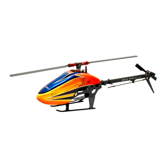
- Page 1 190mm Main Blade Instruction Manual...
- Page 2 - Visit the Oxy Heli web site www.oxyheli.com to download the latest version of the manual. - Inside Box 2 you will find your serial number card. Please take a moment to visit the Oxy Heli web site and follow the instructions to register your helicopter and serial number.
- Page 3 Chapter 2, Important Notes IMPORTANT NOTE: This model helicopter has been designed and produced to be a high performance 3D machine. With its simple design and low parts count, pilots of all skill levels will appreciate its easy repairability. This is not a toy. Please take care assembling the model, and take care and responsibility when you fly it.
- Page 4 Chapter 3, Required Tools for assembly TOOLS REQUIRED Small Tip - Flat Screw Driver 1.5mm Hex Screw Driver (High quality) Two Tools Required Philips head screw driver 1.3mm Hex Screw Driver (High quality) Needle nose pliers Uniball Pliers Caliper page 4...
- Page 5 Chapter 4: What's inside the box INSIDE THE MAIN BOX Canopy, BOX 1-1, Box 1/Bag 11 Main Frame Set, Box 1/Bag 10 Landing Gear Set, Tail Set Asembly Parts. Box 3/Bag 1 Tail Boom Set, Serial Number Card, Box 3/Bag 2 190mm CP Main Blade Box 2/Bag 1 Boom Clamp Set, Box 2/Bag 2 Battery Tray Set, Box 2/Bag 3 Main Gear Set,...
- Page 6 Chapter 4: What's inside the box INSIDE THE BOX 1 Canopy Head Set Assembly Parts Frame Set Assembly Parts Box 1/Bag 10 Landing Gear Set Tail Set Asembly Parts Box 1/Bag 11 Main Frame Set BOX 1 page 6...
-
Page 7: Specifications
Configuration examples Since the Oxy2 is a high performance 3D RC helicopter, we suggest using high quality power components including motor, battery and ESC. Remember the Oxy 2 is a 200 class heli – use light components to maximize flight time and performance. -
Page 8: Important Notes
Chapter 6: Tail Assembly Vertical Fin Assembly Tail Case Assembly (Box 1/Bag 1) (Box 1/Bag 2) OXY0515- Tensioner Bushing 2 x SMR682Z-ZZ- 2.5X6X2.6 Radial Bearing OXY0516 - Tensioner Spacer OXY0524- 2.55x4.5x0.1 Shim 2 x MR52-W2 2X5X2 Radial Bearing OXY0527- 2x3.5x0.1 Shim Important Note: This part, for tuning reasons, comes factory pre assembled,... -
Page 9: Tail Assembly
Chapter 6:Tail Assembly Tail Shaft Assembly (Box 1/Bag 4) Tail Shaft 16T Important Note: This part, for tuning reasons, comes factory pre assembled, it ready to use. Tail Pitch Slider Assembly (Box 1/Bag 5) OXY0255 - Tail pitch Slider Haft Moon 2 x OXY0522- Link Control OXY0541 - Tail Pitch... - Page 10 Chapter 6: Tail Assembly Carbon Fiber Tail Push Rod Assembly (Box 3/Bag 1) OXY0519-Threaded Rod M1.4X7mm REF 1mm OXY0536-Al Tail Push OXY0526-Plastic OXY0584-STD Tail Push Rod Rod Terminal Linkage Ball 3mm Important Note: This part, for tuning reasons, comes factory pre assembly, it ready to use.
- Page 11 Chapter 6: Tail Assembly Tail Assembly Step 1 Tail Boom Pre Assembly B305MXL-Timing Belt (Box 1/Bag 8) 2 x M1.6X5 Hex Cap Screw 2 x M1.6X5 Hex OXY0258-Tail Cap Screw Tail Case Assembly Case Center Tail Assembly Step 2 Belt Tensioner Pre Assembly 4 x M1.6 x5 Hex OXY0540 -...
- Page 12 Chapter 6: Tail Assembly Tail Assembly Step 4 M1.6x10 Hex Cap Screw, do not over tighten the Screw Important Note: Once assembly finish, check if the system can slide and move without friction. If tail system is assembled correctly, it should move smoothly.
- Page 13 Chapter 6: Tail Assembly Tail Assembly Step 5 Step 5-1: Tail belt is showed straight coming out, form tail boom. Be careful to check the belt if not twisted inside the boom. Use a flashlight to check inside the boom, for better vision. Rotate the belt 90 degrees CCW as shown.
-
Page 14: Main Frame Assembly
Chapter 7: Main Frame Assembly Boom Clamp Assembly (Box 2/Bag 1) Pulley Guide Belt Assembly 2 x MR52-W2-2X5X2 Radial Bearing OXY0532- 1.6X13.8 Pin 2 x OXY0460 - Bell Crank Bushing OXY0242-Pulley Important Note: Guide Belt this part, for tuning reasons, comes factory pre assembled, it ready to use 2 x Pulley Guide Belt Assembly... - Page 15 10h before fly Motor Installation OXY2 support two size of motor fitting (13mm/M2 and 19mm/M2.5), choose the correct holes dependig on the used Motor. Use Hex Cap Screw M2x5 for 13mm holes Use Button Head Screw M2.5x5 for 19mm holes...
- Page 16 Chapter 7: Main Frame Asembly Main Frame Asembly Step 1 OXY0263-Main Frame Box 1/Bag 11 OXY2 support two kind of Servo dimension options. Lower Bearing Block can be installed in two Frame position. Follow note for Servo type A or B install. Max 10mm...
- Page 17 Chapter 7: Main Frame Assembly Main Frame Assembly Step 2 Boom Clamp Assembly 6 x M2x6 Motor Asembly Hex Cap Screw OXY0081- 2.1X5.5X1 Washer 6 x M2x6 Hex Cap Screw Note: Don't fully tighten yet. Wait future neccessary assembly step. Main Frame Assembly Step 3 Right Canopy Mount Assembly.
- Page 18 Chapter 7: Main Frame Asembly Main Frame Asembly Step 4 6 x M2x6 Hex Cap Screw 2 x OXY0081- 2.1X5.5X1 Washer 6 x M2x6 Hex Cap Screw Note: Don't fully tighten yet. Wait future neccessary assembly step. Main Frame Asembly Step 5 OXY0251 - Anti Rotation Guide Box 1-1/Bag 11...
- Page 19 Chapter 8: Main Frame Alignment OXY0459-Main Shaft (Box 1-1/Bag 8) Install main shaft with frame assembly on a flat surface, push down on both frames together and then fully tighten all M1.6x5 hex cap screws (x8) holding the bearing blocks. Flat Surface page 19...
-
Page 20: Transmission Assembly
OXY2 Tail Assembly Before next assembly step check carefully Tail Belt assembly position as shown. OXY0247 - Main Gear Bushing OXY2 support two kind of servo dimension, use specific main gear bushing spacer for Servo type B. Main Gear 110T-55T pulley... - Page 21 Chapter 9: Transmission Assembly Note: hole's position on main shaft are symmetrical. M2x8 Hex Cap Screw don't over tighten M2x8 Hex Main Gear Cap Screw Assembly In order to check the belt installation, we recommend to follow two simple steps: 1- Check with light, look inside the boom from the tail case and check the belt is only twisted 90 degrees.
-
Page 22: Belt Tension & Adjustment
Chapter 10: Belt Tension & Adjustment Main Shaft Collar and Tail Belt tensioning. Pull up Main Shaft Push down Main Shaft Collar OXY0451-Main Shaft Collar Tail Belt Pulley Note: Before tensioning Tail Belt, check if correctly positioned in both Belt Pulleys. M1.6x5-Hex Cap Screw don't over tighten... -
Page 23: Main Rotor Assembly
Chapter 11: Main Rotor Assembly Main Grip Assembly (Box 1-1/Bag 5) 2.70 add silicon F2.5-6GC-2.5x6x3 grease Thrust Bearing 2.50 OXY0228-Main Grip Important Note: This part, for tuning reasons, comes factory pre assembled with grease and loctite. It is 2 x SMR682X_ZZC_3 ready to use. - Page 24 Chapter 11: Main Rotor Assembly Main Rotor Assembly (Box 1-1/Bag 5) Flat surface Stepped surface DFC Arm are not symmetrical. Flat surface faced to Screw. Step faced to Main Grip. OXY0447 - Important Note: DFC Pin Screw This part comes pre assembled WITHOUT thread lock.
- Page 25 Chapter 11: Main Rotor Assembly Main Rotor Assembly step 1 Head Assembly Swash Plate Assembly Main Rotor Assembly step 2 All Screw in this step need add loctite, don't over tighten. 2 x M1.6x6 Hex M2x8 Hex Cap Screw Cap Screw page 25...
-
Page 26: Esc Installation
Chapter 12: ESC Installation Be carefully Motor wire Double - side Tape and ESC will not touch (Box 2/Bag 4) Motor/Pinion. use your choice of connector rated Battery wires 2 x Cable Tie Motor wires Use 3 x cable ties, to secure the Throttle ESC wire to the main frame. Use the Frame built-in socket for best holding. -
Page 27: Chapter 13 - Flybarless Installation
Chapter 13: Flybarless Installation For extra FBL support we Flybarless Unit suggest to add Electronic Position 1 Hook and Loop as shown. Double - Side Tape (Box 2/Bag 4) The FBL system can be installed at the bottom or top of the boom clamp. We suggest to use the bottom for easy wiring and servo removal. -
Page 28: Chapter 14 - Servo & Servo Rod Prepareration
Chapter 14: Servo & Servo Rod Prepareration - You should now do some initial setup of your FBL unit and servos. - We recommend you select a new model in your transmitter, and reset your FBL unit and start with a clean setup in it as well. - After binding your transmitter to the receiver system used with the FBL unit, work your way through the FBL setup instructions to the point you plug in your servos. -
Page 29: Chapter 15 - Cylic Servo Installation
Chapter 15: Cylic Servo Installation 6 x TCEM1.6x5 Hex Cap Screw 6 x TCEM1.6x5 3 x Servo Rod Assembly Hex Cap Screw 6 x OXY0525- 1.6X3.5X0.5 Washer Servo Layout page 29... - Page 30 Chapter 16: Tail Servo Installation 4 x M1.6x5 - Hex Cap Screw 2 x OXY0525- 1.6X3.5X0.5 Washer Tail Push Rod Assembly (Box 3/Bag 1) Bottom Heli View 4 x M1.6x5 - Hex Cap Screw Arm position with centered Rudder stick. Maximun Tail Servo Size Note: Max 12mm With Rudder Stick centered...
- Page 31 Chapter 17: Landing Gear & Battery Installtion Landing Gear & Battery Installtion Electronic Hook & Loop Important Note: Use both double sided Hook (Box 2/Bag 4) and Loop Velcro and the included battery straps to fully secure the battery pack. 4x M2x8 Self Tapping Screw don't over tighten 4x M2x8...
- Page 32 Chapter 19: Adjustment Servo With Leveler Before Fly: Now complete the setup of your FBL system. In the Accessories Bag you will find an Oxy 3 Swash Plate Leveler. This Tool is designed to fit under the Swash Plate without disassembly any parts. This simple tool will both level the swash and give the Zero Pitch Position.
- Page 33 Chapter 19: Adjustment Servos with Leveler Front Servo Left Servo Right Servo page 33...
- Page 34 Chapter 20: Canopy Installation page 34...
-
Page 35: Table Of Contents
Chapter20: Exploded View, Main Rotor Code Name QTY. OXY0227 OXY2-CENTER HUB OR3W1.5 Oring ID3x1.5 OXY0446 OXY2 Sindle Shaft OXY0229 OXY2-Dampener Bushing OXY0524 2.55x4.5x0.1 Shim OXY0528 OXY2-Damperner Spacer TCEM1.6X6 M1.6x6 Hex Cap Screw TCEM2X8 M2X8HEX CAP SCREW OXY0525 1.6x3.5x0.5 Washer TCEM1.6X5 M1.6X5 Hex Cap Screw... -
Page 36: Pos Code
Linkage ball 3x1.5mm - DR1265 TCEM2X6 M2X6HEX CAP SCREW OXY0525 1.6x3.5x0.5 Washer TCEM1.6X5 M1.6X5 Hex Cap Screw OXY0263 OXY2-Main Frame OXY0533 OXY2-Main Gear 55t Pulley OXY0538 CF Main Gear Cover FHSM2X4 M2x4 Flat Head Screw OXY0247 OXY2-Main Gear Bushing OXY0459 OXY2-Main Shaft OXY0451... -
Page 37: Tcem1.6X5
OXY2-Main Frame OXY0300 OXY2- Battery Tray OXY0452 OXY2-Boom Clamp OXY0242 OXY2-Pulley Guide Belt MR52-W2 2X5X2 Radial Bearing OXY0460 OXY2 Bell Crank Bushing OXY0532 1.6x13.8mm Pin OXY0453 Boom Lock Rod OXY0237 OXY2-Bottom Landing Gear OXY0240 OXY2-Right Landing Gear OXY241 OXY2-Left Landing Gear... -
Page 38: Oxy0454 23 Oxy0521
Chapter20: Exploded View, Tail System Code Code Name QTY. Name QTY. OXY0578 OXY2 Tail Boom STD ( Black ) TCEM1.6X5 M1.6X5 Hex Cap Screw OXY0543 OXY2-Al Tail Case TCEM1.6x8 M1.6x8 Hex Cap Screw SMR682Z-ZZ 2.5X6X2.6 Radial Bearing TCEM2X12 M2X12 Hex Cap Screw OXY0524 2.55x4.5x0.1 Shim... -
Page 39: Oxy2-Center Hub
10 x Plastic Linkage Ball 3mm 10 x M1.4X11 Threaded Rod SP-OXY2-007 - SP-OXY2-008 - OXY2 - SP-OXY2-009 - OXY2 - Main Shaft, 2 PCS Spindle Shaft, 2 Set 3mm Steel Ball, 10 PCS 2 x OXY2-Main Shaft 2 x OXY2 Sindle Shaft 10 x Linkage ball 3x1.5mm... -
Page 40: Oxy2-Lower Swash Plate
SP-OXY2-011 - OXY2 - SP-OXY2-013 - OXY2 - Swash Plate, Service Bag Swash Plate, Set Main Grip Service Bag 1 x OXY2-Lower Swash Plate 4 x 2.5X6X2.6 Radial Bearing 1 x Ball Holder 1 x OXY2-Upper Swash Plate 2 x 2.5x6x3 Thrust Bearing... - Page 41 SP-OXY2-019 -OXY2 - Motor Mount, Set CNC Main Gear Main Frame, 2PCS 1 x OXY2 - Motor Mount 1 x CNC Main Gear 55t Pulley 6 x M2X6 Hex Cap Screw 1 x CF Main Gear Cover 4 x 2.1X5.5X1 Washer 3 x M2x4 Flat Head Screw 2 x M2.5x5 Button Screw...
- Page 42 Plastic Landing Gear Skid, Left / Right Battery Tray 3D Boom Clamp Mount 3D 2 x OXY2-Boom Clamp 1 x OXY2-Right Landing Gear, black 1 x OXY2- Battery Tray 4 x Boom Lock Rod 1 x OXY2-Left Landing Gear, black...
- Page 43 SP-OXY2-034 - OXY2 - CNC Aluminum Tail Grip, Set Tail Rotor - Service Bag CNC Aluminum Tail Bell Crank 1 x OXY2-AL Tail Bell Crank 2 x OXY2-AL Tail Grip 2 x 2X5X2 Radial Bearing 4 x 2X5X2.3 Radial Bearing 4 x 2X5X2.3 Radial Bearing...
- Page 44 Tail Pitch Slider - Service Bag CNC Tail Push Rod, Set 1 x OXY2-Tail Pitch Slider Bushing 1 x OXY2-SST Tail Pitch Slider Ring 1 x std tail push Carbon Rod 2 x 3x7x2 Radial Bearing 2 x OXY2-Al Tail Push Rod Terminal...
- Page 45 SP-OXY2-028-OXY2 - SP-OXY2-045 - OXY2 - Blade Holder Battery Oring , 4PC 190mm Carbon Plastic Main Blade 1 x OXY2 Blader Holder 4 x Oring 55W2.5 2pcs 190mm Carbon Plastic Main Blade SP-OXY2-046 - OXY2 - SP-OXY2-047 - OXY2 -...
- Page 46 Chapter 21: Spare Parts SP-OXY2-055 - OXY2 - SP-OXY2-059 - OXY2 - SP-OXY2-060 - OXY2 - Pinion 18T - 2.5mm Motor Shaft Vertical Fin Sticker Yellow Vertical Fin Sticker Orange 1 x Pinion 18T- M0.4 - 2.5mm Motor Shaft 1 x Vertical Fin Sticker yellow...
Need help?
Do you have a question about the oxy2 and is the answer not in the manual?
Questions and answers