Acer Iconia A1-810 Service Manual
Hide thumbs
Also See for Iconia A1-810:
- User manual (53 pages) ,
- Product and safety information (71 pages)
Table of Contents
Advertisement
Quick Links
Advertisement
Table of Contents

Related Manuals for Acer Iconia A1-810


Summary of Contents for Acer Iconia A1-810
- Page 1 Iconia A1-810 SERVICE GUIDE...
-
Page 2: Revision History
Revision History Refer to the table below for the updates made to this Iconia A1-810 service guide. Date Chapter Updates Service guide files and updates are available on the ACER/CSD website. For more information, go to http://gcsd.acer.com.tw/GCSD_Portal/.The information in this guide is subject to change without notice. - Page 3 Conventions The following conventions are used in this manual: WARNING: Indicates a potential for personal injury. CAUTION: Indicates a potential loss of data or damage to equipment. IMPORTANT: Indicates information that is important to know for the proper completion of a procedure, choice of an option, or completing a task.
- Page 4 Acer-authorized Service Providers: Your Acer office may have a different part number code than those given in the FRU list in this service guide. You must use the list provided by your regional Acer office to order FRU parts for repair and service of customer machines.
-
Page 5: Table Of Contents
CHAPTER 1 Hardware Specifications Features ..........1-5 Operating System . - Page 6 CHAPTER 3 Machine Maintenance Machine Disassembly and Replacement....3-3 Recommended Equipment ......3-3 Replacement Requirements.
- Page 7 FRU List Iconia A1-810 Exploded Diagrams ..... . . 6-4 Main Assembly ........6-4 FRU List .
- Page 9 CHAPTER 1 Hardware Specifications...
- Page 10 Features ..........1-5 Operating System .
- Page 11 AC Adapter ........1-20 System Power Management .
-
Page 13: Features
Hardware Specifications and Configurations Features The following is a summary of the tablet’s many features. Operating System Android Jelly Bean 4.2 Performance MediaTek 1.2 GHz quad-core processor System Memory 1 GB of RAM 8 or 16 GB of flash memory ... -
Page 14: Communication
Communication Webcam Front camera 0.3M camera Fixed focus Rear camera 5M camera Wireless and networking Bluetooth 4.0 WiFi IEEE 802.11b/g/n Storage Subsystem Card reader microSD Card slot (up to 32 GB) Power Adapter and Battery Power adapter 10 W, 5 V 2A AC adapter... -
Page 15: Accessories
Accessories Setup poster USB cable AC adapter Warranty MicroSD card (optional) Pouch (optional) Bluetooth keyboard (optional) Dimensions and Weight Dimensions Width × Depth × Height: 145.7 × 11.1 × 208.7 mm (5.7 × 0.5 × 8.2 in) ... -
Page 16: Tablet Tour
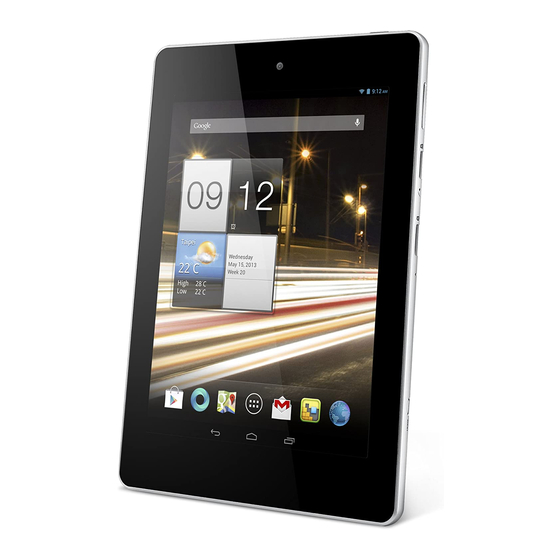
Tablet Tour This section provides an overview of the features and functions of the tablet. Front View Figure 1-1. Front View Table 1-1. Front View Item Description Front-facing camera A 0.3-megapixel camera for video chats and self-portrait images. Touchscreen 7.9-inch, 1024 x 768 pixel capacitive touchscreen. Hardware Specifications and Configurations... -
Page 17: Right View
Right View Figure 1-2. Right View Table 1-2. Right View Item Description Volume control key Increases and decreases the tablet volume. microSD Card slot Insert a microSD Card into the slot. Microphone Receives audio for video chats and Internet calls. Shutdown pinhole Insert a small thin object (such as a paperclip) to shut down the tablet. -
Page 18: Top View
Top View Figure 1-3. Top View Table 1-3. Top View Item Description Power button Long press to turn the tablet on, press briefly to turn the screen on/off or enter sleep mode; press and hold to turn the tablet off. 1-10 Hardware Specifications and Configurations... -
Page 19: Bottom View
Bottom View Figure 1-4. Bottom View Table 1-4. Bottom View Item Description Micro USB port Connects to a computer via a USB cable. Supports OTG function and also serves as the charging port for the AC adapter. Headphone jack Connects to audio devices (e.g., speakers, headphones). 1-11 Hardware Specifications and Configurations... -
Page 20: Back View
Back View Figure 1-5. Back View Table 1-5. Back View Item Description Rear camera A 5-megapixel camera for taking high-resolution images and video. Speaker Emits audio. 1-12 Hardware Specifications and Configurations... -
Page 21: Touchscreen Basics
Touchscreen Basics Your tablet uses a touchscreen for selecting items and entering information. Use your finger to tap the screen. Tap: Touch the screen once to open items and select options. Drag: Hold your finger on the screen and drag across the screen to select text and ... -
Page 22: Specification Tables
Specification Tables Tablet Specifications Item Metric Imperial Dimensions Width 14.57 cm 5.74 in Depth 1.11 cm 0.45 in Height 20.87 cm 8.22 in Weight WiFi: 410 g WiFi: 0.90 lb 3G: 430 g 3G: 0.95 lb Input power Operating voltage 5.35 V Operating current (max) Temperature... - Page 23 Item Metric Imperial Shock Operating Amplitude: 105G Duration: 2 ms Wave form: Half-sine Axes: ±X, ±Y, +Z Test Time: 1 times per axis Nonoperating Amplitude: 220G Duration: 2 ms Wave form: Half-sine Axes: ±X, ±Y, ±Z Test Time: 1 time per axis Random vibration Operating Frequency: 10 ~ 500 Hz...
- Page 24 System Board Major Chips Item Specification MediaTek MT8125 quad-core processor PMIC MediaTek MT6320 Audio codec MediaTek MT6320 Audio AMP MediaTek MT6320 Sensor Gyro sensor INVEN SENSE MPU-6050 G-sensor Kionix KXTIK-1004 P-sensor Azoteq IQS128TSR Memory Nanya DDR3L 1600 4Gb NT5CC256M16BP-DI eMMC Kingston Nand 16 GB KE4CN4K6A (FW v4.5) LF+HF LCD panel AUO 8' XGA None Glare B080XAT01.1 LED touch panel...
- Page 25 Processor Specifications Item CPU Speed CPU Core Max Clock Package Core Freq Tech Voltage MT8125 1.2 GHz quad cortex 1200 MHz 28 nm TFBGA 1.1 V System Memory Item Specification Memory controller Nanya DDR3L 1600 4Gb NT5CC256M16BP-DI Hynix DDR3L 1600 4Gb H5TC4G63AFR-PBA Memory size 4 GB DDR3L System Memory - eMMC...
- Page 26 Item Specification Pixel configuration Viewing angle (H/V) Brightness 220 nit Contrast ratio 500:1 (Typ.) Response time 25 ms Backlight Edge light type Weight Physical size Supported LCD Resolutions Resolution 16 bits 32 bits Others 1024x768, 60 Hz 16:9 Audio Codec Item Specification Controller...
- Page 27 Wireless, Bluetooth LAN Item Specification Module Azurewave AW-NH520 SiP (Mediatek MT6628T chipset) Frequency band Protocols and data rates WLAN + BT + FM + GPS, 4 in 1 supported WLAN 802.11 b/g/n dual band single stream (20/40MHz) with LNA and PA integration Bluetooth 3.0+HS and V4.0 Low Energy support with PA ...
- Page 28 AC Adapter Item Specification Vendor and models Phihong 10W 5V/2A PSAI10R-050Q(A)-R LF Input rating 10 W Input AC current (max) 100-240 V, -0.3 A, 50-60 Hz Output 5.35 V, 2 A System Power Management Item Specification G3 Mechanical Off Only EC working G2/S5 Soft Off Only EC working G0 Working...
-
Page 29: Diagnostic Utilities
CHAPTER 2 Diagnostic Utilities... - Page 30 PQAA Tool ......... . 2-3 Requirements .
-
Page 31: Pqaa Tool
Diagnostic Utilities This tablet has a set of software tools designed to diagnose problems with its hardware components. PQAA Tool Requirements PC with Windows 7 (x64) USB cable to connect the tablet to PC Installing the PQAA Tool 1. - Page 32 3. On your PC, extract the <.android.rar> file. 4. Copy the .android folder to the Users directory. Figure 2-2. Users Directory 5. Extract the <Driver_Auto_Installer_v1.1236.00.rar> file to your computer to install the Device drivers. 6. Locate the <Install.bat> file in the Driver_Auto_Installer_v1.1236.00 folder. Run the <Install.bat>...
- Page 33 7. Extract the <platform-tools.rar> file to your computer. 8. Extract the <Mango_PQAA_Build20130505_V1.01.rar> file to your computer. 9. Copy all the files in the Mango_PQAA_Build20130505_V1.01 folder to the Platform_tools folder. Figure 2-4. Platform Tools Folder 10. Open the MS-DOS command prompt window by clicking Start > Run, enter <cmd> and then click OK.
- Page 34 11. Enter the <cd platform-tools> command prompt. Figure 2-6. cd platform-tools Folder 12. Enter the <adb devices> command prompt to check if the tablet is connected to the PC. If the tablet is successfully connected to the PC, the tablet serial number displays on the screen.
- Page 35 13. In Windows mode, locate the <push.bat> file in the platform-tools folder. 14. Double-click the <push.bat> file to push or transfer tools to the tablet. Figure 2-8. Push Installation 15. Locate the <install.bat> file in the platform-tools folder. 16. Double-click the <install.bat> file to install the APK files. If you want to uninstall the APK files, run the <uninstall.bat>...
- Page 36 17. After the installation is complete, the following diagnostic tools appear on the Application menu. Mango_Button Mango_Display Mango_PQAA Mango_SD Card Mango_TouchPanel Mango_Vibration Figure 2-10. Diagnostic Tools Diagnostic Utilities...
-
Page 37: Running The Pqaa Tool
Running the PQAA Tool 1. On the tablet, open the Application menu. 2. Tap the Mango_PQAA icon to run the tool on the tablet. The diagnostic tool tests the touch panel, display, SD card, tablet buttons, and vibration functionality. Figure 2-11. Diagnostic Tool Main Menu 3. - Page 38 2-10 Diagnostic Utilities...
- Page 39 CHAPTER 3 Machine Maintenance...
- Page 40 Machine Disassembly and Replacement....3-3 Recommended Equipment ......3-3 Replacement Requirements.
-
Page 41: Machine Disassembly And Replacement
Machine Maintenance Machine Disassembly and Replacement This chapter contains step-by-step procedures on how to disassemble the notebook computer for maintenance and troubleshooting. Cable paths and positioning may not represent the actual model. During the removal and installation of the components, ensure all available cable channels and clips are used and that the cables are replaced in the same position. -
Page 42: Pre-Disassembly Instructions
Pre-disassembly Instructions Before proceeding with the disassembly procedure, make sure that you do the following: 1. Unplug the AC adapter and all cables from the tablet. Figure 3-1. AC Adapter 2. Turn off power to the tablet (even when locked) by pressing and holding the power button for one second. -
Page 43: Disassembly Process
Disassembly Process The flowcharts provided in the succeeding disassembly sections illustrate the entire disassembly sequence. Observe the order of the sequence to avoid damage to any of the hardware components. For example, if you want to remove the mainboard, you must first remove the keyboard, then disassemble the inside assembly frame in that order. -
Page 44: Removing The Microsd Card
Removing the MicroSD Card 1. Remove the MicroSD card that is present. 2. Push against the MicroSD card, as if you were pushing it further into the slot and pull the card out. Figure 3-3. MicroSD Card Machine Maintenance... -
Page 45: Removing The Back Cover
Removing the Back Cover 1. Use your thumb or insert a small flat-blade screwdriver, or a non-marring scribe below the MicroSD card slot to create a small gap. 2. Gently pry the cover away to unlock the locking latches on the back cover from the middle frame. - Page 46 4. Once the top is done, start on the bottom side doing the same thing to unlock the back cover from the middle frame. Figure 3-6. Back Cover Locking Latches — Bottom Side 5. Grasp the back cover with your right hand, use your left thumb to push up the cover from the middle frame.
- Page 47 7. Once the first latch is unlocked, grasp the cover by its rear edge and rotate the cover off the tablet. Figure 3-8. Back Cover Locking Latches — Right Side Figure 3-9. Back Cover Machine Maintenance...
-
Page 48: Removing The Battery
Removing the Battery 1. Perform the “Removing the Back Cover” procedure described on page 3-7. 2. Disconnect the battery cable from the mainboard connector. If a black tape is attached to the connector cable, detach the tape first and disconnect the battery cable from the mainboard connector. -
Page 49: Removing The Gps And Wlan Antenna Cables
Removing the GPS and WLAN Antenna Cables 1. Perform the “Removing the Back Cover” procedure described on page 3-7. 2. Disconnect the GPS and WLAN antenna cables from the mainboard. GPS antenna WLAN antenna Figure 3-12. GPS and WLAN Antenna Cables 3. - Page 50 4. Carefully peel off tin foil tapes securing the GPS and WLAN antenna cables to the middle frame. Figure 3-14. GPS and WLAN Antenna Cable Tapes 5. Remove the cables from the middle frame. Figure 3-15. GPS and WLAN Antenna Cables 3-12 Machine Maintenance...
-
Page 51: Removing The Vibration Motor Module
Removing the Vibration Motor Module 1. Perform the “Removing the Back Cover” procedure described on page 3-7. 2. Disconnect the vibration motor cable from the mainboard connector. Figure 3-16. Vibration Motor Cable 3. Release the vibration motor cable from the cable guides and then remove the module from the middle frame. -
Page 52: Removing The Speaker Module
Removing the Speaker Module 1. Perform the “Removing the Back Cover” procedure described on page 3-7. 2. Disconnect the speaker cable from the mainboard connector. Figure 3-18. Speaker Module Cable 3. The speaker module is secured to the middle frame with a double-sided adhesive tape. Carefully detach the speaker module from the middle frame. -
Page 53: Removing The Audio And Usb Boards
Removing the Audio and USB Boards 1. Perform the “Removing the Back Cover” procedure described on page 3-7. 2. Use the pull tab to disconnect the audio and USB board connector cable from the mainboard connector. Figure 3-20. Audio and USB Board Connector Cable 3. - Page 54 4. Remove the bracket from the audio board. Figure 3-22. Audio Board Bracket 5. Remove the one screw securing the USB board to the middle frame. Figure 3-23. USB Board Screw Table 3-3. Screw Step Screw Quantity Torque Screw Type USB Board Disassembly M1.6 x L3.5 0.7+15% to 0.7-15%...
- Page 55 6. Remove the audio and USB boards from the middle frame. Figure 3-24. Audio and USB Boards NOTE: NOTE: A circuit board that is > 10cm has been highlighted with a yellow rectangle in Figure 3-24. Follow the local regulations for disposing this type of circuit board. 7.
-
Page 56: Removing The Rear Camera Module
Removing the Rear Camera Module 1. Perform the “Removing the Back Cover” procedure described on page 3-7. 2. Open the camera cable’s connector latch and then disconnect the cable from the mainboard. Figure 3-26. Camera Cable 3. Remove the rear camera module from the middle frame. Figure 3-27. -
Page 57: Removing The Mainboard
Removing the Mainboard 1. Perform the “Removing the Back Cover” procedure described on page 3-7. 2. Open the LCD cable’s connector latch and then disconnect the cable from the mainboard. Figure 3-28. LCD Cable 3. Open the touchscreen cable’s connector latch and then disconnect the cable from the mainboard. - Page 58 4. Strip off the mylar tape located on the top right corner of the mainboard. Figure 3-30. Mylar Tape 5. Remove the five screws securing the mainboard. Figure 3-31. Mainboard Screws Table 3-4. Screws Step Screw Quantity Torque Screw Type Mainboard Disassembly M1.6 x L3.5 0.7+15% to 0.7-15%...
- Page 59 6. Remove the mainboard from the LCD and middle frame assembly. Figure 3-32. Mainboard NOTE: NOTE: A circuit board that is >10 cm2 has been highlighted with a yellow rectangle in Figure 3-32. Follow the local regulations for disposing this type of circuit board. 3-21 Machine Maintenance...
-
Page 60: Removing The Front Camera Module
Removing the Front Camera Module 1. Perform the “Removing the Back Cover” procedure described on page 3-7. 2. Perform the “Removing the Mainboard” procedure described on page 3-19. 3. Disconnect the camera cable from the mainboard. Figure 3-33. Camera Cable 4. -
Page 61: Removing The Lcd And Middle Frame Assembly
Removing the LCD and Middle Frame Assembly 1. Perform the “Removing the Back Cover” procedure described on page 3-7. 2. Perform the “Removing the Mainboard” procedure described on page 3-19. Figure 3-35. LCD and Middle Frame Assembly 3-23 Machine Maintenance... -
Page 62: Reassembly Process
Reassembly Process Replacing the Front Camera Module 1. Slide the front camera module into the corner of the mainboard. Figure 3-36. Front Camera Module 2. Connect the camera connector cable to the mainboard. Figure 3-37. Camera Connector Cable 3-24 Machine Maintenance... -
Page 63: Replacing The Lcd And Middle Frame Assembly
Replacing the LCD and Middle Frame Assembly 1. Prepare the LCD and middle frame assembly for mainboard installation. 2. Ensure that the LTE main and auxilliary rubber foams are attached to the middle frame. LTE main LTE auxilliary rubber foam rubber foam Figure 3-38. -
Page 64: Replacing The Mainboard
Replacing the Mainboard 1. Position the mainboard into the LCD and middle frame assembly. Figure 3-40. Mainboard 2. Secure the mainboard to the middle frame with the five screws. Figure 3-41. Mainboard Screws Table 3-5. Screws Step Screw Quantity Torque Screw Type Mainboard Reassembly M1.6 x L3.5... - Page 65 3. Attach the mylar tape to the top right corner of the mainboard. Figure 3-42. Mylar Tape 4. Connect the touchscreen cable to the mainboard and then close the connector latch. Figure 3-43. Touchscreen Cable 3-27 Machine Maintenance...
- Page 66 5. Connect the LCD cable to the mainboard and then close the connector latch. Figure 3-44. LCD Cable 3-28 Machine Maintenance...
-
Page 67: Replacing The Rear Camera Module
Replacing the Rear Camera Module 1. Insert the rear camera module into the middle frame. Figure 3-45. Rear Camera Module 2. Connect the camera cable to the mainboard and then close the connector latch. Figure 3-46. Camera Cable 3-29 Machine Maintenance... -
Page 68: Replacing The Audio And Usb Boards
Replacing the Audio and USB Boards 1. Connect the audio cable to the audio board and then connect the USB cable to the USB board. USB board Audio board Figure 3-47. Audio and USB Board Connector Cable 2. Position the audio and USB boards into the middle frame. Figure 3-48. - Page 69 3. Secure the USB board to the middle frame with one screw. Figure 3-49. USB Board Screw Table 3-6. Screw Step Screw Quantity Torque Screw Type USB Board Reassembly M1.6 x L3.5 0.7+15% to 0.7-15% Kgf-cm 4. Place the audio board bracket on top of the audio board. Figure 3-50.
- Page 70 5. Secure the audio board bracket using the two screws. Figure 3-51. Audio Board Bracket Screws Table 3-7. Screws Step Screw Quantity Torque Screw Type Audio Board Bracket M1.6 x L6 0.7+15% to 0.7-15% Reassembly Kgf-cm 6. Connect the audio and USB board connector cable to the mainboard. Figure 3-52.
-
Page 71: Replacing The Speaker Module
Replacing the Speaker Module 1. Align the speaker to the mounting pins on the middle frame and then push down to lock in place. Figure 3-53. Speaker Module 2. Connect the speaker cable to the mainboard. Figure 3-54. Speaker Cable 3-33 Machine Maintenance... -
Page 72: Replacing The Vibration Motor Module
Replacing the Vibration Motor Module 1. Position the vibration motor module into the middle frame. 2. Route the cable to the cable guides on the middle frame. Figure 3-55. Vibration Motor Module 3. Connect the vibration motor cable to the mainboard. Figure 3-56. -
Page 73: Replacing The Gps And Wlan Antenna Cables
Replacing the GPS and WLAN Antenna Cables 1. Place the GPS and WLAN antenna cables on the middle frame. antenna WLAN antenna Figure 3-57. GPS and WLAN Antenna Cables 2. Secure the cables to the middle frame with the tin foil tapes. Figure 3-58. - Page 74 3. Route the cables to the cable guides on the middle frame and then use mylar tapes to secure in place. Figure 3-59. GPS and WLAN Antenna Cables 4. Connect the GPS and WLAN antenna cables to the mainboard. GPS antenna WLAN antenna Figure 3-60.
-
Page 75: Replacing The Battery
Replacing the Battery 1. Apply double-sided adhesive tape to the middle frame so that the battery can be attached to the frame. Figure 3-61. Adhesive Tapes 2. Position the battery into the tablet. 3. Rotate the battery down until it meets the middle frame and then press down firmly to adhere to the middle frame. - Page 76 4. Connect the battery cable to the mainboard. If necessary, secure the cable connection with a black tape. Figure 3-63. Battery Cable 3-38 Machine Maintenance...
-
Page 77: Replacing The Back Cover
Replacing the Back Cover 1. Place the left side of the back cover on the middle frame, aligning the back cover with the middle frame latches. Figure 3-64. Back Cover 3-39 Machine Maintenance... - Page 78 2. Gently press down on the left and right and then the top and bottom sides of the back cover with your thumbs. Push it in until it clicks and locks into place. Figure 3-65. Back Cover — Left and Right Sides Figure 3-66.
-
Page 79: Replacing The Microsd Card
Replacing the MicroSD Card 1. Insert the MicroSD card into the slot until it clicks into place. Figure 3-67. MicroSD Card 3-41 Machine Maintenance... - Page 80 3-42 Machine Maintenance...
-
Page 81: Troubleshooting
CHAPTER 4 Troubleshooting... - Page 82 Introduction ......... 4-3 General Information .
-
Page 83: Introduction
NOTE: NOTE: The diagnostic tests are intended for Acer products only. Non-Acer products, prototype cards, or modified options can give false errors and invalid system responses. 1. Obtain as much detailed information as possible about the problem. -
Page 84: Power On Issues
Power On Issues If the tablet does not power on, perform the following, one at a time, to correct the problem. Do not replace a non-defective FRU. Figure 4-1. Power On Issue Troubleshooting... -
Page 85: No Display Issues
No Display Issues If the display fails, perform the following, one at a time. Do not replace a non-defective FRU: Figure 4-2. No Display Issue Abnormal Video If the video appears abnormal, perform the following one at a time. 1. Boot the tablet. If permanent vertical/horizontal lines or dark spots appear in the same location, the LCD panel is faulty and should be replaced. -
Page 86: Lcd Picture Failure
LCD Picture Failure If the LCD picture fails, perform the following, one at a time. Do not replace a non-defective FRU: Figure 4-3. LCD Picture Failure Troubleshooting... -
Page 87: Touchscreen Failure
Touchscreen Failure If the touchscreen fails to respond, perform the following, one at a time. Do not replace a non-defective FRU: Figure 4-4. Touchscreen Failure Troubleshooting... -
Page 88: Internal Speaker Failure
Internal Speaker Failure If internal speakers fail, perform the following, one at a time. Do not replace a non-defective FRU: Figure 4-5. Internal Speaker Failure Troubleshooting... -
Page 89: Internal Microphone Failure
Internal Microphone Failure If internal microphones fail, perform the following, one at a time. Figure 4-6. Internal Microphone Failure Troubleshooting... -
Page 90: Usb Failure
USB Failure If the USB fails, perform the following, one at a time. Do not replace a non-defective FRU: Figure 4-7. USB Failure 4-10 Troubleshooting... -
Page 91: Front Camera Failure
Front Camera Failure If the front camera fails, perform the following, one at a time. Do not replace a non-defective FRU: Figure 4-8. Front Camera Failure 4-11 Troubleshooting... -
Page 92: Rear Camera Failure
Rear Camera Failure If the rear camera fails, perform the following, one at a time. Do not replace a non-defective FRU: Figure 4-9. Rear Camera Failure 4-12 Troubleshooting... -
Page 93: Device Vibration Failure
Device Vibration Failure If the vibrating alarm fails, perform the following, one at a time. Do not replace a non-defective FRU: Figure 4-10. Device Vibration Failure 4-13 Troubleshooting... -
Page 94: Card Reader Failure
Card Reader Failure If the card reader fails, perform the following, one at a time. Do not replace a non-defective FRU: Figure 4-11. Card Reader Failure 4-14 Troubleshooting... -
Page 95: Wireless And Bluetooth Function Test Failure
Wireless and Bluetooth Function Test Failure If the wireless function fails, perform the following, one at a time. Do not replace a non-defective FRU: Figure 4-12. Wireless Function Failure 4-15 Troubleshooting... -
Page 96: Gps Function Failure
GPS Function Failure If the GPS function test fails, perform the following, one at a time. Do not replace a non-defective FRU: Figure 4-13. GPS Function Failure 4-16 Troubleshooting... -
Page 97: Other Functions Failure
Other Functions Failure 1. Check if the Apps and Android operating system are functioning correctly. 2. Check if external modules are functioning correctly. 3. Check component connection to the mainboard. 4. Change mainboard to check if current one is defective. 4-17 Troubleshooting... -
Page 98: Intermittent Problems
Intermittent Problems Intermittent system hang problems can be caused by a variety of reasons that have nothing to do with a hardware defect, such as: cosmic radiation, electrostatic discharge, or software errors. FRU replacement should be considered only when a recurring problem exists. When analyzing an intermittent problem, perform the following: 1. -
Page 99: Undetermined Problems
Verify that the power supply being used at the time of the failure is operating correctly. 1. Remove power from the device. 2. Visually check the components for damage. If any problems are found, replace the FRU. 3. Remove or disconnect all of the following devices: Non-Acer devices MicroSD Card ... - Page 100 4-20 Troubleshooting...
-
Page 101: Jumper And Connector Locations
CHAPTER 5 Jumper and Connector Locations... - Page 102 Mainboard Layout ........5-3 Top View ......... .5-3 Bottom View.
-
Page 103: Mainboard Layout
Jumper and Connector Locations Mainboard Layout Top View Figure 5-1. Mainboard — Top Table 5-1. Mainboard — Top Code Component CCDF8 Rear camera cable connector PSWSW1 Power button VOLSW1 Volume up button VOLSW2 Volume down button CARD1 MicroSD card reader DMIC1 Microphone RSTSW1... -
Page 104: Bottom View
Bottom View Figure 5-2. Mainboard — Bottom Table 5-2. Mainboard — Bottom Code Component WIFI1 WLAN antenna connector GPS1 GPS antenna connector BATCN1 Battery connector LCDTH8 Touchscreen cable connector Vibration motor cable connector LCM8 LCD cable connector USBCN1 Audio and USB board cable connector SPK1 Speaker cable connector LTE1... -
Page 105: Fru List
CHAPTER 6 FRU List... - Page 106 Iconia A1-810 Exploded Diagrams ..... . . 6-4 Main Assembly ........6-4...
- Page 107 FRU (Field Replaceable Unit) List This chapter provides users with a FRU (Field Replaceable Unit) listing in global configurations for the Iconia A1-810. Refer to this chapter whenever ordering for parts to repair or for RMA (Return Merchandise Authorization). NOTE:...
-
Page 108: Iconia A1-810 Exploded Diagrams
Iconia A1-810 Exploded Diagrams Main Assembly Figure 6-1. Main Assembly Exploded Diagram Table 6-1. Main Assembly Exploded Diagram Description Part Number LCD display assembly Middle frame Battery KT.00203.004 Rear camera module 56.18006.771 Front camera module NC.21411.01G GPS antenna 50.L1DN1.005 Mainboard NB.L1D11.001... - Page 109 Table 6-1. Main Assembly Exploded Diagram Description Part Number USB board 55.L1DN1.001 Audio board bracket 33.L1DN1.001 Speaker module 23.40ABV.011 FRU (Field Replaceable Unit) List...
-
Page 110: Fru List
FRU List Category Description Part No. ACCESSORY AC PLUG PHIHONG EU RPE-N(AWS)-R AP.0050P.002 AC PLUG PHIHONG UK RPK-N(AWS)-R AP.0050P.003 AC PLUG PHIHONG US RPA(AWS)-R AP.0050P.004 AC PLUG PHIHONG AU RPS-N(AWS)-R AP.0050P.005 AC PLUG PHIHONG CN RPC(AWS)-R AP.0050P.006 AC PLUG PHIHONG BZ RPB(ACE)-R XZ.70200.143 AC PLUG PHIHONG AR RPN(ACE)-R XZ.70200.142... - Page 111 Category Description Part No. CABLES VIB CABLE 4MM BL4I2T-C17T MANGO 50.L1DN1.003 C.A. MANGO USB CABLE HL NCONN 50.4VL08.301 C.A. MANGO USB CABLE HT NCONN 50.4VL08.001 C.A. MANGO USB CABLE ICT NCONN 50.4VL08.101 C.A. MANGO USB CABLE WS NCONN 50.4VL08.201 C.A. MANGO TP FPC CABLE ICT 50.4VL04.011 C.A.
- Page 112 Category Description Part No. ASSY TOUCHPANEL W/MIDDLE COVER 6M.L1DN1.001 MANGO ASSY MID COVER MANGO 60 WIFI NSPK RESERVE COMMUNICATION MODULE ANTENNA MANGO GPS ANT 50.L1DN1.005 ANTENNA MANGO WIFI ANT 50.L1DN1.006 LCD 7.85" XGA AUO B079XAT02.0 MAINBOARD MANGO MB WIFI+NH520 MT8125 8GB NB.L1D11.001 13206-1.D MANGO MB WIFI+NH520 MT8125...
- Page 113 Category Description Part No. RUB MANGO MIC RUBBER 47.4VL07.101 RUB MANGO MIC RUBBER JIN 47.4VL07.001 RUB MANGO LTE MAIN RUBBER 47.4VL03.101 RUB MANGO LTE MAIN RUBBER JIN 47.4VL03.001 RUB MANGO LTE AUX RUBBER 47.4VL04.101 RUB MANGO LTE AUX RUBBER JIN 47.4VL04.001 SPEAKER SPEAKER MANGO SPK...
- Page 114 6-10 FRU (Field Replaceable Unit) List...
-
Page 115: Test Compatible Components
CHAPTER 7 Test Compatible Components... -
Page 116: Android Os Environment Test
Android OS Environment Test......7-4... - Page 117 Test Compatible Components This computer’s compatibility is tested and verified by Acer’s internal testing department. All of its system functions are tested under Android OS environment. Refer to the following lists for components, adapter cards, and peripherals which have passed these tests.
- Page 118 Android OS Environment Test Vendor Type Description Part No. MediaTek MT8125 CPU(BGA) MediaTek MT8 MT8125 KC.MT807.125 Qual-Core FCCSP 1.2G 1M Cortex-A7 515 balls w/ NEON MT8389 W CPU(BGA) MediaTek MT8 MT8389W KC.MT807.389 Qual-Core FCCSP 1.2G 1M Cortex-A7 515 balls w/ NEON HSPA+ Modem PMIC MediaTek...
- Page 119 Vendor Type Description Part No. Huawei LTE NGFF Huawei LTE NGFF Module Card NC.21311.005 Module Card ME906V LTE NGFF Huawei LTE NGFF Module Card NC.21311.006 Module Card ME906E WIFI/BT/GPS (b/g/n) Azurewave SIP on board AW-NH520(MT6628Q)WLAN/BT/FM/GP NC.23611.00E module AW-NH520T(MT6628T) WLAN/BT/FM NC.23611.00P RF Chipset Mediatek MT6167 for...
- Page 120 Vendor Type Description Part No. Chicony 10W, 5V 2A Adapter Chicony Power 10W 5V/2A KP.0100H.001 W010R010L-AC01 LF Fix AC for US 10W, 5V 2A Adapter Chicony Power 10W 5V/2A KP.0100H.002 W010R010L-AC01 LF Fix AC for EU 10W, 5V 2A Adapter Chicony Power 10W 5V/2A KP.0100H.003 W010R010L-AC01 LF Fix AC for China Battery...
- Page 121 CHAPTER 8 Online Support Information...
-
Page 123: Online Support Information
This section describes online technical support services available to help users repair their Acer Systems. For distributors, dealers, ASP or TPM, please refer the technical queries to a local Acer branch office. Acer Branch Offices and Regional Business Units may access our website. - Page 124 Online Support Information...
Need help?
Do you have a question about the Iconia A1-810 and is the answer not in the manual?
Questions and answers