Table of Contents
Advertisement
Right choice for ultimate yield
LSIS strives to maximize customers' profit in gratitude of choosing us for your partner.
Programmable Logic Controller
XGB Built-in Positioning
XGT Series
Read this manual carefully before
installing, wiring, operating, servicing
or inspecting this equipment.
Keep this manual within easy reach
for quick reference.
User's Manual
XBM-DN16S
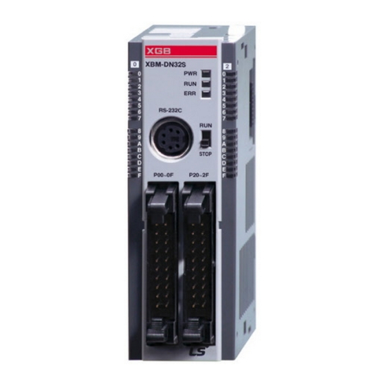
XBM-DN32S
XBC-DN20S(U)
XBC-DN30S(U)
XBC-DN40SU
XBC-DN60SU
XBC-DP20SU
XBC-DP30SU
XBC-DP40SU
XBC-DP60SU
XBC-DN32H(/DC)
XBC-DN64H(/DC)
http://eng.lsis.biz
XEC-DN20SU
XEC-DN30SU
XEC-DN40SU
XEC-DN60SU
XEC-DP20SU
XEC-DP30SU
XEC-DP40SU
XEC-DP60SU
XEC-DN32H
XEC-DN64H
XEC-DP32H
XEC-DP64H
Advertisement
Table of Contents

Related Manuals for LSIS XBM-DN16S


Summary of Contents for LSIS XBM-DN16S
- Page 1 Right choice for ultimate yield LSIS strives to maximize customers' profit in gratitude of choosing us for your partner. Programmable Logic Controller XGB Built-in Positioning XGT Series User’s Manual XBM-DN16S XEC-DN20SU XBM-DN32S XEC-DN30SU XBC-DN20S(U) XEC-DN40SU XBC-DN30S(U) XEC-DN60SU XBC-DN40SU XEC-DP20SU XBC-DN60SU...
- Page 2 Safety Instruction Before using the product … For your safety and effective operation, please read the safety instructions thoroughly before using the product. ► Safety Instructions should always be observed in order to prevent accident risk by using the product properly and safely. ►...
- Page 3 Safety Instruction Safety Instructions when designing Warning Please, install protection circuit on the exterior of PLC to protect the whole control system from any error in external power or PLC module. Any abnormal output or operation may cause serious problem in safety of the whole system.
- Page 4 Safety Instruction Safety Instructions when designing Caution I/O signal or communication line shall be wired at least 100mm away from a high-voltage cable or power line. If not, it may cause abnormal output or operation due to noise. Safety Instructions when designing Caution Use PLC only in the environment specified in PLC manual or general standard of data sheet.
- Page 5 Safety Instruction Safety Instructions when wiring Warning Prior to wiring, be sure that power of PLC and external power is turned off. If not, electric shock or damage on the product may be caused. Before PLC system is powered on, be sure that all the covers of the terminal are securely closed.
- Page 6 Safety Instruction Safety Instructions for test-operation or repair Warning Don’t touch the terminal when powered. Electric shock or abnormal operation may occur. Prior to cleaning or tightening the terminal screws, let all the external power off including PLC power. If not, electric shock or abnormal operation may occur.
- Page 7 Safety Instruction Safety Instructions for waste disposal Caution Product or battery waste shall be processed as industrial waste. The waste may discharge toxic materials or explode itself.
- Page 8 2013.7 1. Adding Motor Wiring Examples(XGT-Servo:XDL-S) 1-9,10 2. Adding Modules(XB(E)C-DPxxSU) 2-2,3 5-47,95 3. Adding PWM instruction ※ The num ber of User’ s m anual is indicated right part of the back cover. ⓒ 2008 LSIS Co.,Ltd. All Rights Reserved.
- Page 9 User’s Manual. The User’s Manual describes the product. If necessary, you may refer to the following description and order accordingly. In addition, you may connect our website(http://eng.lsis.biz/) and download the information as a PDF file.
-
Page 10: Table Of Contents
◎ Contents ◎ ..........1-1~1-11 Chapter 1 General 1.1 General .......................... 1-1 1.1.1 Purpose of position function ................... 1-1 1.1.2 Features ........................ 1-2 1.2 Performance specifications .................... 1-3 1.2.1 Performance specifications of XGB built-in positioning ......... 1-3 1.3 Operation Sequence of Positioning ................1-4 1.3.1 Operation Sequence of Positioning ................ - Page 11 Chapter 3 Before Positioning ............... 3-1~3-58 3.1 Positioning Function ....................... 3-1 3.1.1 Positioning function list ................... 3-1 3.1.2 Position control ..................... 3-4 3.1.3 Speed control ......................3-5 3.1.4 Speed/position switching control ................3-7 3.1.5 Position/speed switching control ................3-8 3.1.6 Linear interpolation control ..................3-9 3.1.7 Simultaneous start control ..................
- Page 12 Chapter 5 Positioning Instructions .............. 5-1~5-92 5.1 Positioning Instruction Alarm ..................5-1 5.2 Details of Positioning Instructions ................... 5-3 5.2.1 Origin Return Instructions ..................5-3 5.2.2 Fixed Origin Setting Instruction ................5-7 5.2.3 Direct Starting Instruction ..................5-9 5.2.4 Indirect Starting Instruction ................. 5-12 5.2.5 Straight Interpolation Starting Instruction ..............
- Page 13 5.3.10 Deceleration Stop Function Block ..............5-70 5.3.11 Position Synchronization Function Block ............5-73 5.3.12 Speed Synchronization Function Block .............. 5-77 5.3.13 Position Override Function Block ............... 5-80 5.3.14 Speed Override Function Block ................5-82 5.3.15 Positioning Speed Override Function Block ............5-84 5.3.16 Inching Start Function Block ................
- Page 14 7.2.6 Simultaneous Start ..................... 7-15 7.2.7 Position Synchronous Start ................7-17 7.2.8 Speed Synchronous Start ................... 7-20 7.2.9 Emergency Stop ....................7-23 7.2.10 Jog Operation ....................7-25 7.2.11 Speed Override ....................7-27 7.2.12 Position Override ....................7-29 7.2.13 Speed override with Position ................7-32 7.2.14 Speed, Position, and Parameter Teaching ............
- Page 15 Appendix 2 Positioning Instruction and K area List ....APP.2-1~APP.2-43 APP 2.1 Positioning instruction list ................APP.2-1 APP 2.2 Positioning Dedicated K area List ..............APP.2-2 APP 2.2.1 K area of positioning basic parameter..........APP.2-2 APP 2.2.2 K area of positioning home parameter ..........APP.2-3 APP 2.2.3 Positioning operation data K area ............
-
Page 16: Chapter 1 General
Chapter 1 General Chapter 1 General XGB series transistor output type contains 2 positioning axes. This manual describes the specifications and usage of positioning. 1.1 General 1.1.1 Purpose of position function The purpose of position function is to exactly move an object from the current position to a designated position and this function executes highly precise position control by sending a position pulse string signal to types of servo drive or stepping motor control drive. -
Page 17: Features
Chapter 1 General 1.1.2 Features Positioning function features the followings. (1) Max. two axis, 100kpps positioning - XGB PLC can execute positioning of up to 2 axes with up to 100kpps. Diversity of positioning function - XGB PLC contains various functions necessary for position system such as position control at any temporary position or constant speed operation. -
Page 18: Performance Specifications
Chapter 1 General 1.2 Performance specifications 1.2.1 Performance specifications of XGB built-in positioning The performance specifications of positioning function are as follows. Here standard type indicates XBM-DN□□S/ XBC-DN□□S(U) and high end type indicate XBC(XEC)-DN□□H. Each type is indicated as ‘S’ type and ‘H’ type. XGB Basic Unit (Transistor output ) Type Item... -
Page 19: Operation Sequence Of Positioning
Chapter 1 General 1.3 Operation Sequence of Positioning 1.3.1 Operation Sequence of Positioning Operation sequence is as follows. XBM-DN**S: V1.2 or above XBC-DN**H: V2.2 or above XEC-DN**H: V3.0 or above 1- 4... -
Page 20: Flow Of Position Signal
Chapter 1 General 1.3.2 Flow of position signal Flow of position signal is as follows. < XGB Positioning signal flow > 1- 5... -
Page 21: Io Signal Allocation
Chapter 1 General 1.4 I/O Signal Allocation 1.4.1 Allocation of I/O signal for standard type (S type) In case of S type, external I/O signal for built-in function is allocated as follows. (1) Pin array of I/O connector Pin array of I/O connector of XGB standard type transistor type basic unit is as follows. Input Output P000 P000... -
Page 22: Allocation Of Standard Type (S Type) Output Signal
Chapter 1 General (3) Example of wiring the external input signal Example of wiring the external input signal is as follows. < Example of wiring the external input signal > 1.4.2 Allocation of standard type (S type) output signal (1) Allocation of output signal When using the positioning function, the output signal is allocated as shown below. - Page 23 Chapter 1 General 1.4.3 Allocation of compact type (S/H type) input signal In case of compact standard/high-end type, external input signal for built-in positioning is allocated as follows (1) I/O terminal block array Array of XGB transistor output type basic unit is as figure below. * based on XBC-DN32H Input (P0) Output (P4)
- Page 24 Chapter 1 General (2) Allocation of external input signal Input contact point no. XBC-DN(P) XEC-DN(P) Signal name Operation content Reference Axis □□S(U)/H □□H Detected at the falling edge of input X axis P0008 %IX0.0.8 External lower contact point limit Normally Detected at the falling edge of input (LimitL) Y axis...
- Page 25 Chapter 1 General 1.4.4 Allocation of compact type (S/H type) output signal (1) Allocation of output signal In case of using built-in positioning of XGB compact standard/high-end type main unit, output signal is allocated as follows. Operation content Input contact point no. Signal name Reference Pulse + Direction...
-
Page 26: I/O Wiring By Using Smart Link Board
Chapter 1 General 1.5 I/O wiring by using Smart Link Board 1.5.1 Smart link board When using positioning function, easy wiring is available by connecting the I/O connector with smart link board. The available smart link and I/O cable are as follows. Smart link Connection cable The no. - Page 27 Chapter 1 General (2) Wiring of SLT-T40P and XGB main unit Wiring of XGB main unit through SLP-T40P and SLT-CT101-XBM is as follows XBM-DN32S SLT-CT101-XBM SLP-T40P At this time, relationship of XGB I/O signal and Smart link board terminal number is as follows. The following figure describes signal allocation when SLT-CT101-XBM is used as connection cable.
-
Page 28: Chapter 2 General Specification
• Pulse waveform : half sine wave (3 times to X, Y and Z directions, each) AC: ±1,500 V Rectangular Test specifications DC: ± 900 V impulse noise of LSIS Electrostatic IEC61131-2 Voltage : 4kV (contact discharge) discharge IEC61000-4-2 Radiating... -
Page 29: Power Specification
Chapter 2 General Specification 2.2 Power Specification Power specification of XGB series main unit is as follows. 2.2.1 Standard type(XBM-DN□□S) power specification Item Specification Rated input voltage DC24V Input voltage range DC20.4~28.8V(-15%, +20%) Inrush current or below Peak Max. 1A (Typ. 550 ㎃) Input Input current Efficiency... - Page 30 Chapter 2 General Specification 2.2.3 Compact high-end type (XB(E)C-DR/DN/DP□□H) power specification Specification XEC- XEC- XBC- XBC- Item DR32H DR64H /DR32H DR64H /DN32H /DN64H /DN32H /DN64H /DP32H /DP64H Rated input AC 100 ~ 240 V voltage Input voltage AC85~264V(-15%, +10%) range Inrush current or less Peak...
-
Page 31: I/O Specification
Chapter 2 General Specification 2.3 I/O Specification It describes I/O specification when P0000~P000F is used for built-in positioning. For using P0000~P000F as general I/O, refer to XGB user manual for hardware 2.3.1 Input Specification (1) Standard type input contact point specification Contac X axis P0000... - Page 32 Chapter 2 General Specification (2) Compact standard type input contact point specification Contact X axis P0008 P0009 P000C P000D point Ref. Y axis P000A P000B P000E P000F External External upper Signal name HOME lower limit limit Rated input DC24V (DC20.4~28.8V (-15/20%, ripple rate 5% or less)) voltage Rated input About 4 ㎃/24V...
- Page 33 Chapter 2 General Specification (3) Compact high end type input contact point specification P0008 P0009 P000C P000D X axis Contact %IX0.0.8 %IX0.0.9 %IX0.0.12 %IX0.0.13 point Ref. P000A P000B P000E P000F Y axis %IX0.0.10 %IX0.0.11 %IX0.0.14 %IX0.0.15 External External upper Signal name HOME lower limit limit...
-
Page 34: Output Specification
Chapter 2 General Specification 2.3.2 Output specification (1) Standard type output contact point specification X axis P0020 P0022 Conta Ref. ct no. Y axis P0021 P0023 Signal name Pulse string output Direction output Rated load DC5~24V (DC4.75~26.4V) voltage Max. load 0.1A/1 point or below current Insulation... - Page 35 Chapter 2 General Specification (2) Compact standard type output contact point specification X axis P00040 P00042 Conta Ref. ct no. Y axis P00041 P00043 Signal name Pulse string output / CW output Direction output / CCW output Rated load DC5~24V (DC4.75~26.4V) voltage Maximum load 0.1A/1or less...
- Page 36 Chapter 2 General Specification (3) Compact high-end type output contact point specification P00020 P00022 X axis Cont %QX0.0.0 %QX0.0.2 Ref. P00021 P00023 Y axis %QX0.0.1 %QX0.0.3 Signal name Pulse string output / CW output Direction output / CCW output Rated load DC5~24V (DC4.75~26.4V) voltage Maximum load...
-
Page 37: Output Pulse Level
Chapter 2 General Specification 2.3.3 Output pulse level Output pulse of XGB built-in positioning consists of Pulse + Direction or CW+CCW like figure below. At this time, output level of Low Active and High Active can be specified by positioning parameter and K area flag dedicated for positioning (X axis: K4871, %KX7793, Y axis: K5271, %KX8433). -
Page 38: Chapter 3 Before Positioning
Chapter 3 Before positioning Chapter 3 Before Positioning It describes the function of position control, operation parameter setting, operation data setting, K area for positioning, servo driver setting and programming. 3.1 Positioning Function 3.1.1 Positioning function list Positioning function of XGB built-in positioning is as follows. For more detail, refer to ch.5.2. - Page 39 Chapter 3 Before positioning Positioning Operation description Instruction Ref. function Ch.5.2.8 APM_PTV Ch.5.3.9 Operation Position/speed pattern switching control Position control is executed by start command and it is switched to speed Operation control by switching signal and stops after deceleration by stop command . Ch.5.2.5 APM_LIN Ch.5.3.6...
- Page 40 Chapter 3 Before positioning Positioning Instru Operation description Ref. ction function Ch.5.2.1 APM_ Ch.5.3.2 Operation pattern Home return It goes to home direction and detects the mechanical origin Operation At this time, home method can be specified by operation parameter. Ch.5.2.12 Ch.5.3.13 APM_...
-
Page 41: Position Control
Chapter 3 Before positioning 3.1.2 Position control Position control is to move the designated axis from start address (present position) up to target address (movement). There are two position control methods, absolute and incremental. (1) Control by absolute coordinates (Absolute coordinates) Object moves from start address to target address. -
Page 42: Speed Control
Chapter 3 Before positioning (2) Control by incremental coordinates Object moves from current position as far as the address set in operation data. At this time, target address is based on start address. Direction is determined by sign (+,-). • In case Address is positive number: forward positioning (Direction increasing address) •... - Page 43 Chapter 3 Before positioning • In case of speed control, some items as figure below doesn’t affect the operation. These items don’t affect the operation in case of speed - If Control is specified as SPD, coordinates, pattern, method, M code, dwell time doesn’t affect the operation.
-
Page 44: Speed/Position Switching Control
Chapter 3 Before positioning 3.1.4 Speed/position switching control • It change speed control to position control by switching command (VTP instruction). • In case of speed/position switching control, items affecting the operation are different according to control method. These items don’t affect the operation in case of speed These items don’t affect the operation when changed into position - First, object moves by speed control. -
Page 45: Position/Speed Switching Control
Chapter 3 Before positioning • If step no. 1 in table 3-4 starts, object moves forward by speed control because Control is SPD and Address is positive number. • If speed/position switching command (VTP instruction) is executed during speed control, current position will be initialized as 0 and object moves by position control until 1000. -
Page 46: Linear Interpolation Control
Chapter 3 Before positioning Switching signal <Figure 3-5 Operation of position/speed switching control> Remark • Position/speed switching command is executed only when each axis is operating. If it is executed during stop, it may cause error. • If speed/position switching command is executed during operation by position control, the command is ignored and causes error. - Page 47 Chapter 3 Before positioning 3) Setting of operation pattern - In case of main axis, operation pattern should be specified as ‘END’ or ‘KEEP’. In case it is specified as ‘CONT’, it operates as ‘KEEP’. - In case of subsidiary, pattern doesn’t affect the operation, it operates according to main axis pattern.
- Page 48 Chapter 3 Before positioning < Figure 3-7 operation of linear interpolation control > (2) Control by incremental coordinates It executes the linear interpolation control based on current position by incremental coordinates. At this time, Address of operation data means how long object moves from current position. Direction is determined sign of Address.
- Page 49 Chapter 3 Before positioning • If linear interpolation is executed, main axis is determined according to moving amount of X and Y axis. In table 3-7, since moving amount of X axis is larger than Y, X axis becomes main axis. •...
- Page 50 Chapter 3 Before positioning 3.1.8 Sync control •In sync control, position or speed of subsidiary axis is synchronized with that of main axis. There are two types in sync control, speed sync control and position sync control. (1) Position sync control •...
-
Page 51: Homing
Chapter 3 Before positioning • It can be executed when origin of subsidiary axis is not determined. • Since subsidiary axis moves according to speed of main axis, whether main axis moves by speed control or position control doesn’t matter. At this time, direction of subsidiary axis is same as that of main axis. - Page 52 Chapter 3 Before positioning (2) Origin detection after DOG Off The operations by Home Return instruction using DOG and origin signal are as follows. (a) If home return command (ORG instruction) is executed, it accelerates toward a preset home return direction and with Home high speed. (b) During operating with Home Return High speed, if rising edge of DOG signal occurs, it operates with Home Return Low speed and monitors if there is falling edge of DOG signal.
- Page 53 Chapter 3 Before positioning Remark • In speed-decreasing section, origin is not determined. Though DOG changed from “On” to “Off” and Origin signal is inputted in speed-decreasing section, origin is not determined. Origin is determined at first Origin signal after speed-decreasing section •...
- Page 54 Chapter 3 Before positioning Origin detection after deceleration with DOG set “On” Operations by home return instruction using DOG and origin signal are as follows. (a) If homing command(ORG instruction) is executed, it accelerates toward a set home direction and operates at home high speed. (b) At the moment, if an external entry, DOG signal is entered, it decelerates and operates at home return low speed.
- Page 55 Chapter 3 Before positioning Origin detection by DOG It is used when determining origin by using the only DOG. (a) If homing command (ORG instruction) is executed, it accelerates to home direction set in Home Parameter and it homes with high speed. (The above figure is example when homing direction is forward) (b) While target is homing with high speed, if rising edge of DOG occurs, target speed decreases and change its direction.
-
Page 56: Position And Speed Override
Chapter 3 Before positioning 3.1.10 Position and speed override • Override means changing target address or speed without stop during positioning. The XGB positioning provides three type of override, position override, speed override, speed override with position. (1) Position override If changing a target position during positioning operation with positioning data, it may be changed by using position override command (POR instruction). - Page 57 Chapter 3 Before positioning (2) Speed override While positioning by operation data, it is used to change operation speed by speed override command (SOR instruction). • Speed override command is available during acceleration, constant speed operation section and executing speed override instruction in deceleration section during operation or dwell section may cause Error 377 but the operation continues.
-
Page 58: Positioning Stop Signal
Chapter 3 Before positioning 3.1.11 Positioning stop signal (1) Stop instruction and stop factors Stop instructions and factors are summarized as follows and divided into individual stop and • concurrent stop. Individual axis stop instructions or the stop factors affect the only axis (axes) of which stop instruction is “On”... - Page 59 Chapter 3 Before positioning Stop Process and Priority (a) Stop Process • Since positioning operation is not complete if it stops due to deceleration stop instruction, After Mode among M code modes is not “On” because it does not generate positioning completion signal.
-
Page 60: Manual Operation
Chapter 3 Before positioning positioning operation after executing origin determination (Home Return, floating origin and the current position preset) in case it is operated with absolute coordinate or in determined origin. 3.1.12 Manual operation In general, manual operations refer to jog operation, inching operation which don’t use operation data. (1) Jog operation •... -
Page 61: Stroke Upper/Lower Limits
Chapter 3 Before positioning 3.1.13 Stroke Upper/Lower Limits Positioning is subject to external input stroke limit (external input upper limit, external input lower limit) and software stroke limit (software upper limit, software lower limit). External input stroke upper/lower limits • External input stroke limit is an external input connector of positioning; external input upper limit/external input lower limit. -
Page 62: Output Of Positioning Completion Signal
Chapter 3 Before positioning 3.1.14 Output of positioning completion signal • Regarding positioning completion output time, the completion signal(X axis: 4202, %KX6722, Y axis: K4302, %KX6882) is on and it turns off after ‘on’ is maintained as much as 1 scan time after positioning is completed during single operation, repeat operation, continuous operation, sequential operation, linear interpolation operation, speed/position switching operation (with position indicated during constant speed operation) and inching operation. -
Page 63: Positioning Parameter
Chapter 3 Before positioning 3.2 Positioning Parameter It describes positioning parameter and operation data setting. 3.2.1 Positioning parameter setting sequence Positioning parameter can be set more than V1.2 (high end type can be set more than XG5000 • V2.2) and it has the following sequence. (This manual is described by using XG5000 V2.2.) (1) Opening parameter setting window Select [Parameter] ->... - Page 64 Chapter 3 Before positioning (2) Setting parameter • Positioning parameter setting window is classified into basic parameter and Home parameter. • Each item can be set independently. • For detail setting of basic parameter, refer to 3.2.3. • For detail setting of Home parameter, refer to 3.2.4. Type Item Description...
- Page 65 Chapter 3 Before positioning (3) Operation data setting If the user select ‘X Axis Data’ or ‘Y Axis Data’ tap on the positioning parameter setting window, • the user can set operation data of 30 steps as show below. • Standard type can set up to 30 steps, high-end type can set up to 80 steps. <...
- Page 66 Chapter 3 Before positioning (4) Writing to PLC •After setting of positioning parameter and operation data per each axis, download them to PLC •Selecting [Online] -> [Write], ‘Write’ dialog box is displayed. In order to download parameter, select ‘Parameter’ and click ‘OK’. Remark •...
-
Page 67: Relationship Between Positioning Parameter And Dedicated K Area
Chapter 3 Before positioning 3.2.2 Relationship between positioning parameter and dedicated K area XGB built-in positioning function executes the positioning control by using parameter and K area dedicated for positioning. Here describes relationship between positioning parameter and K area. Internal memory configuration related with XGB built-in positioning is as follows. <... -
Page 68: Setting Basic Positioning Parameters
Chapter 3 Before positioning 3.2.3 Setting basic positioning parameters It describes the range of setting basic parameters and special K area for positioning. K area for positioning X-axis Y-axis Item Range Initial value Data size XBM/XBC XBM/XBC K4870 K5270 Positioning 0: No use, 1 : use %KX7792 %KX8432... - Page 69 Chapter 3 Before positioning Positioning •Determine whether to use positioning. • If not using positioning function, set it ‘0: no use’ while for use, it should be set to ‘1: use’. • If setting it as ‘1:use’, though it doesn’t execute the instruction related with positioning, it is controlled by positioning.
- Page 70 Chapter 3 Before positioning •M code output mode set in the parameter is applied to all operation step of each axis. •The user can select one M code output mode among three modes, NONE, WITH, AFTER. According to each setting value, timing of M code output signal is as follows. (a) NONE mode •In case M code output mode is selected as NONE, though M code is set in operation data, M code doesn’t occur like the following figure.
- Page 71 Chapter 3 Before positioning < M code output timing in case of AFTER mode > (5) Bias speed • Considering that torque of stepping motor is unstable when its speed is almost equal to 0, the initial speed is set during early operation in order to facilitate motor’s rotation and is used to save positioning time.
- Page 72 Chapter 3 Before positioning (c) Bias speed ≤ JOG high speed (If home return speed is set lower than bias speed, it generates Error 133; if operation speed is set lower than bias speed during positioning, it generates Error 153; if JOG high speed is set lower than bias speed, it generates Error 121.) (6) Speed limit •...
- Page 73 Chapter 3 Before positioning • Range of S/W upper limit and lower limit is checked when starting positioning and operating. • If an error is detected by setting software upper/lower limits(software upper limit error: 501, software lower limit error: 502), pulse output of positioning module is prohibited. Therefore, to resume operation after an error is detected, it is prerequisite to cancel ‘No output’.
- Page 74 Chapter 3 Before positioning • The above figure describes difference of backlash setting or no backlash setting. In case of not setting backlash compensation amount, it moves as many as 100,000 pulse forward and changes the direction and moves backward as many as 100,000 pulse. It may cause error by backlash.
-
Page 75: Origin/Manual Parameter Setting For Positioning
Chapter 3 Before positioning • In the case, S/W upper/lower limit detection is available as long as origin is set and the position mark during constant speed operation is “Mark” (11) Use of Upper/Lower Limits • To use upper/lower limits during operation, it should be set as “Use”. •... - Page 76 Chapter 3 Before positioning (1) Home Return method • There are three home return methods as follows. a) DOG/Origin(Off) : -If origin signal is inputted, it detects the origin signal after DOG changes On -> Off. b) DOG/Origin(On) : When DOG is on, it detects the origin after deceleration -If DOG signal is on and origin signal is inputted after deceleration, it detects the origin.
- Page 77 Chapter 3 Before positioning • The range of home return dwell time is between 0 ∼ 50,000 (unit: 1 ㎳) (8) JOG high speed • Jog speed is about jog operation, one of manual operations and is divided into jog low speed operation and jog high speed operation.
-
Page 78: Positioning Operation Data
Chapter 3 Before positioning 3.3 Positioning Operation Data It describes operation data for XGB positioning. If the user select ‘X axis data’ or ‘Y axis data’ tap in the positioning parameter setting window, the following figure is displayed. Each axis can have 30~80 (standard type: 30 steps, compact stand/high-end type: 80steps) steps of operation data. - Page 79 Chapter 3 Before positioning (1) Step number • The range of positioning data serial number is between 1 ~ 30. (compact standard/high-end type is 1~80) • When executing indirect start, simultaneous start, linear interpolation operation, position synchronization and etc., if you designates the step number of data to operate, it operates according to positioning dedicated K area where operation data is saved.
- Page 80 Chapter 3 Before positioning (a) END (SIN) • It refers to execute the positioning to target address by using the data of operation step and complete the positioning after dwell time. • Generally with END operation, position operation is executed according to pre-arranged speed and position like above picture as ladder shape with accelerated, constant, and decelerated intervals.
- Page 81 Chapter 3 Before positioning • It assumes that operation data is as follows to describe END/SIN operation. Step Coord Contr Metho Address Speed Pattern Dwell [㎳] Step [Pulse] code [pls/s] 10,000 1,000 20,000 30,000 1,000 • In the above table, operation pattern is set as END, target moves once by once start command and since Method is set as SIN, the next step becomes ‘current operation step + 1’.
- Page 82 Chapter 3 Before positioning Remark •If the operation mode is set as single, set the operating step number in the IST at 0, then the step specified in the current step number (axis X: K426(%KW426), axis Y: K436 (%KW436)) in area K for positioning. •If the operation mode is set as Repeat and the Repeat step is set at 0, the step stops operating and the next step changes into 0.
- Page 83 Chapter 3 Before positioning 3) Since the operation mode of step 3 is single, the next step is No. 4. 4) Step 4 has been set as end/repeat 1, it operates up to absolute coordinates 40,000 when step 4 operates by the second operation instruction, and stops without dwell time, and the next step points at step 1 which has been designated as the Repeat step.
- Page 84 Chapter 3 Before positioning (4) Repeat Step • Sets the step to repeat when the operation mode is set as Repeat. • The setting range is 1~30 (1~80 for the compact standard/high-end type). (5) Target Position • Sets the movement of the operation of the step. •...
- Page 85 Chapter 3 Before positioning Remark • With M code signal On, if you execute the next operation step number, error code 233 will come out and the operation will not happen. Therefore, for positioning of the next operation step number with M code signal “On,” you must reset M code signal as M code Off instruction (MOF).
-
Page 86: Positioning Status Monitoring And Area K For Input And Output
Chapter 3 Before positioning 3.4 Positioning Status Monitoring and Area K for Input and Output The XGB built-in positioning function controls positioning by using area K for positioning and the parameters. This Chapter describes area K for positioning. For the relations between the XGB built-in positioning parameters and area K, see 3.2.2. XGB built-in positioning area K divides into the bit flag, word, and double word flag. - Page 87 Chapter 3 Before positioning Speed 0: speed not synchronized K4217 K4317 synchronization 1: speed synchronized 0: jog not at low speed Jog low speed K4218 K4318 1: jog at low speed 0: jog not at high speed Jog high speed K4219 K4319 1: jog at high speed...
-
Page 88: Flag For Positioning Instruction And Command
Chapter 3 Before positioning (2) Status Monitoring Data Area (a) XBM/XBC status monitoring area Device Area Variables Status Axis X Axis X Address Properties Address Properties Double Double word Shows current position Current position K422 K432 word Double Double word Shows current speed Current speed K424 K434... - Page 89 Chapter 3 Before positioning Upper/lower limit detection of S/W 0: detection not allowed, allowed during K4684 K5084 1: detection allowed constant speed operation approximate Return-to-origin origin/origin(OFF) K4780~1 K5180~1 method 1: approximate origin/origin (On) K478 K518 2: approximate origin Return-to-origin 0: normal direction, 1: backward K4782 K5182 direction...
- Page 90 Chapter 3 Before positioning the external input starting switch (P000F) turns On. Device Description Device Description Axis X starting external P000F(%IX0.0.15) K4201(%KX6721) Axis X error switch Axis X signal during Axis X starting instruction K4200(%KX6720) K4290(%KX6864) operation flag • The program above is an example of the program that indirectly starts with the operation data of the current step number (K426 word) on axis X by setting the starting signal whenever the external input starting switch (P000F) turns On.
- Page 91 Chapter 3 Before positioning (b) Jog Operation 1) The following program is an example of the program that carries out the jog operation of axis X by turning on/off the flag for commanding the normal/backward direction jog according to the external input signal.
- Page 92 Chapter 3 Before positioning (2) Data Area for Positioning Setting (a) In case of XBM/XBC Device Area Variables Status Axis X Axis Y Address Properties Address Properties Bias speed K0450 Double word K0490 Double word Sets bias speed. Speed limit K0452 Double word K0492 Double word Sets maximum speed limit.
- Page 93 Chapter 3 Before positioning (b) In case of XEC Device area Variables Status Axis X Axis Y Address Properties Address Properties Bias speed %KD225 Double word %KD245 Double word Sets bias speed. Speed limit %KD226 Double word %KD246 Double word Sets maximum speed limit. Acceleration time 1 %KW454 Word...
- Page 94 Chapter 3 Before positioning (3) Status Monitoring and Commanding Flag by Operation Step (a) In case of XBM/XBC (Step 01) Device area Variables Status Axis X Axis Y properties Address Address Double Step 01 target position K0530 K0830 word Double Step 01 operation speed K0534 K0834...
- Page 95 Chapter 3 Before positioning (b) In case of XBM/XBC (Step 01) Device area Variables Status Axis X Axis Y properties Address Address Double %KD265 %KD415 Step 01 target position word Double %KD267 %KD417 Step 01 operation speed word %KW536 %KW836 Step 01 dwell time Word %KW537...
-
Page 96: Chapter 4 Positioning Check
Chapter 4 Positioning Check Chapter 4 Positioning Check This Chapter describes how to test the operation test to check whether the positioning function is well performed before the XGB positioning function is used. 4.1 The Sequence of Positioning Check This is for checking whether the XGB positioning operation is normally performed by carrying out normal and reverse direction jog operation. - Page 97 Chapter 4 Positioning Check (6) Operation Check through Jog Operation • Check the operation of XGB positioning doing jog operation in the following sequence. • This manual describes the axis X operation check when the pulse output mode is PLS/DIR mode and the pulse output level is set as Low Active.
-
Page 98: Making Of Operation Check Program
Chapter 4 Positioning Check 4.2 Making of Operation Check Program The program for operation check used in this manual should be made as follows. The positioning parameters should be set as follows. For setting the positioning parameters, see 3.2. (1) Positioning Basic Parameters Items Range Set Values... - Page 99 Chapter 4 Positioning Check (3) Example of the Program The following is an example of the program for positioning check. (a) In case of XBM, XBC (b) In case of XEC 4- 4...
-
Page 100: Chapter 5 Positioning Instructions
Chapter 5 Positioning Instructions Chapter 5 Positioning Instructions This chapter describes the definitions, functions, use of the positioning instructions used in XGB positioning functions and the program examples. 5.1 Positioning Instruction Alarm The positioning instructions used for XGB positioning are as follows. (1) In case of XBC/XBM Instructi Description... - Page 101 Chapter 5 Positioning Instructions (2) In case of XEC Function Block Description Conditions Remark APM_ORG Start return to the origin Req, Base, Slot, Axis 5.3.2 APM_FLT Set floating origin Req, Base, Slot, Axis 5.3.3 Req, Base, Slot, Axis, Position, speed, dwell time, APM_DST Direct starting code,...
-
Page 102: Details Of Positioning Instructions
Chapter 5 Positioning Instructions 5.2 Details of Positioning Instructions (In case of XBC/XBM) 5.2.1 Origin Return Instructions • Origin return is sued to check the origin of the machine when power is supplied to the machine in general. If the origin return instruction is given, it is executed depending on the setting of the origin return parameter. - Page 103 Chapter 5 Positioning Instructions (1) Origin return Instruction (ORG) Available areas Flag Instruction Step Error Zero Carry D.x R.x stan (F110) (F111) (F112) ○ ○ ○ ○ ○ ○ ○ COMMAND [Area seting] Operand Description Setting range Data size Slot number where positioning modules are XGB is fixed at 0.
- Page 104 Chapter 5 Positioning Instructions Parameter Area K Data size Item Setting range axis Y Properties Data size origin return 1 ∼ 100,000[pps] K473 K513 Read/write Double word speed origin return 0 ~ 10,000[ms] K475 K515 Read/write Word acceleration time origin return 0 ~ 10,000[ms] K476...
- Page 105 Chapter 5 Positioning Instructions (d) Program Operation • The ORG instruction is executed when there is the rising edge of M0000 which was used as the starting signal of the axis X origin return. (It doesn’t work if axis X is operating or in error) 1) If the origin return instruction (ORG instruction) is executed, it is decelerated in the reverse direction as set in the origin return parameter and operates at origin return high speed (50,000pps).
- Page 106 Chapter 5 Positioning Instructions 5.2.2 Floating Origin Setting Instruction • Floating origin setting refers to setting the current position as the origin by force with the instruction without carrying out the actually mechanical origin return. (1) Floating origin Setting Instruction (FLT) Areas available Flag Instruction...
- Page 107 Chapter 5 Positioning Instructions (2) Example of Use of the Instruction • The floating origin setting instruction is described with the example of the following program. • The example of use of the FLT instruction is described on the basis of axis X. (a) Example of the Program (b) Device Used Device...
-
Page 108: Direct Starting Instruction
Chapter 5 Positioning Instructions 5.2.3 Direct Starting Instruction • Direct starting refers to designating the operation data of the target position and speed from the positioning instruction (DST instruction) for operation without using the setting of the step set in the positioning operation data. - Page 109 Chapter 5 Positioning Instructions • The instruction only sets the item of the operation data, and the basic parameter items related to the operation such as the bias speed and speed limit are fixed in the positioning basic parameters. • If you use the DST instruction, the operation pattern is fixed as End operation, and the operation method is fixed as the single operation.
- Page 110 Chapter 5 Positioning Instructions (c) Operation of the Program • If there is the rising edge of M0001 used as the direct starting instruction signal of axis X, the DST instruction is executed. (Not if axis X is operating or in error.) •...
-
Page 111: Indirect Starting Instruction
Chapter 5 Positioning Instructions 5.2.4 Indirect Starting Instruction • Indirect starting refers to execution of the positioning operation by using the operation step data set in the positioning operation data. Indirect Starting Instruction (IST) Areas available Flag Instruction Step Error Zero Carry D.x R.x... - Page 112 Chapter 5 Positioning Instructions (2) Example of Use of the Instruction • The indirect starting instruction is described with the example of the following program. • The example of use of the IST instruction is described on the basis of axis X. (a) Example of the Program (b) Device Used Device...
- Page 113 Chapter 5 Positioning Instructions 2) Since M code is set at 0, it does not appear and as the operation pattern is End, the step number (axis X:K426) of area K is changed into 4, which is step + 1. Remark •...
-
Page 114: Straight Interpolation Starting Instruction
Chapter 5 Positioning Instructions 5.2.5 Straight Interpolation Starting Instruction • Straight interpolation starting refers to the operation so that the path of axes X and Y is straight from the starting address (current stop location) to the target address (target address). •... - Page 115 Chapter 5 Positioning Instructions (a) Function • This instruction is giving the straight interpolation starting instruction to XGB built-in positioning. • The two axes of XGB positioning conduct straight interpolation starting at the rising edge of input condition. • If the instruction is executed, the two axes of XGB positioning carried out the straight interpolation operation according to the axis setting designated in n2.
- Page 116 Chapter 5 Positioning Instructions Repeat Step coordi Operatio Control Operatio Target position Acc./dec. Operation Dwell time Axis nates n pattern method n mode [Pulse] code speed[pls/s] [㎳] Step positio Rel. Single 7,000 positio Rel. Single 2,000 (c) Operation of the Program •...
-
Page 117: Simultaneous Starting Instruction
Chapter 5 Positioning Instructions 5.2.6 Simultaneous Starting Instruction • The simultaneous starting instruction (SST instruction) is for simultaneously starting the steps of the axes set in the instruction. For details, refer to 3.1.7. (1) simultaneous starting instruction (SST) Areas available Flag Instruction Step... - Page 118 Chapter 5 Positioning Instructions (2) Example of Use of the Instruction • The instruction is described with the example of the following program simultaneous starting instruction. (a) Example of the Program (b) Device Used Device Description Data size Example of setting simultaneous starting M0001 instruction signal...
-
Page 119: Speed Position Switching Instruction
Chapter 5 Positioning Instructions 5.2.7 Speed Position Switching Instruction • This is positioning according to the target position by switching the axis operated by speed control to position control through speed/position switching instruction (VTP instruction). For details, refer to 3.1.4. (1) Speed/Position Switching Instruction (VTP) Areas available Flag... - Page 120 Chapter 5 Positioning Instructions (b) Device Used Device Description Data size Example of setting speed/position switching M0001 instruction signal Signal during axis X speed K4211 control K4201 axis X error (c) Operation of the Program • VTP instruction is executed when there is the rising edge of M0001, which was used as the speed/position switching instruction signal.
-
Page 121: Position Speed Switching Instruction
Chapter 5 Positioning Instructions 5.2.8 Position Speed Switching Instruction • This is operation by switching the axis operating by the current position control into speed control by the position/speed switching instruction (PVT instruction). For details, refer to 3.1.5. (1) Position/Speed Switching Instruction (PTV) Areas available Flag Instruction... - Page 122 Chapter 5 Positioning Instructions (b) Device Used Device Description Data size Example of setting position/speed switching M0001 instruction signal signal during axis K4210 position control K4201 axis X error (c) Operation of the Program • PVT instruction is executed when there is the rising edge of M0001, which was used as the position/speed switching instruction signal.
-
Page 123: Deceleration Stop Instruction
Chapter 5 Positioning Instructions 5.2.9 Deceleration Stop Instruction • The currently operating axis is decelerated and stopped at the speed designated by the deceleration stop instruction (STP instruction). For details, refer to 3.1.11. (1) Deceleration Stop Instruction (STP) Areas available Flag Instruction Step... - Page 124 Chapter 5 Positioning Instructions (2) Example of Use of the Instruction • The deceleration stop instruction is described with the example of the following program. (a) Example of the Program (b) Device Used Device Description Data size Example of setting origin return instruction...
-
Page 125: Position Synchronous Instruction
Chapter 5 Positioning Instructions 5.2.10 Main axis position synchronous Instruction • As follows, this is the instruction for synchronous starting according to the current position of the main axis with the axis set in the SSP being the auxiliary axis. For details, refer to 3.1.8. (1) Main axis position synchronous Starting Instruction (SSP) Areas available Flag... - Page 126 Chapter 5 Positioning Instructions • If the instruction is executed, the auxiliary axis stands by without generating actual pulse (the operation status flag of the auxiliary axis (axis X:K4200, axis Y:K4300) turns On), and n2 step of the auxiliary axis is started when n3 axis, which is the main axis, is positioned as set in n1. •...
- Page 127 Chapter 5 Positioning Instructions (c) Operation of the Program • The SSP instruction is executed if there is the rising edge of M0001, which was used as the main axis position synchronous instruction signal. Since the second operand is 1 (axis Y), axis Y is the auxiliary axis, and as the fifth operand is 0(axis X), so the main axis is axis X.
-
Page 128: Speed Synchronous Instruction
Chapter 5 Positioning Instructions 5.2.11 Speed Synchronous Instruction • The speed synchronous instruction (SSS instruction) is for speed synchronization at the set synchronous speed rate and operation when the main axis is started with the axis set in the instruction being the auxiliary axis. For details, refer to 3.1.8. (1) Speed Synchronous Starting Instruction (SSS) Areas available Flag... - Page 129 Chapter 5 Positioning Instructions • The delay time settable for n2 is 1 ~ 10[㎳]. If it gets out of the settable range, error code 357 is issued. • The main axis of n3 is settable between 0 and 9. If it gets out of the settable range, error code 355 is issued Main axis setting Remark...
- Page 130 Chapter 5 Positioning Instructions (b) Operation of the Program • SSS instruction is executed if there is the rising edge of M0001, which was used as the speed synchronous instruction signal. Since the second operand is 1(axis Y), axis Y becomes the auxiliary axis, and because the fifth operand is 0(axis X), the main axis is axis X.
-
Page 131: Position Override Instruction
Chapter 5 Positioning Instructions 5.2.12 Position Override Instruction • The position override instruction (POR) is for changing the target position of the axis being operated for the current positioning into the target position set in the instruction. For details, refer to 3.1.10. (1) position override instruction (POR) Areas available Flag... - Page 132 Chapter 5 Positioning Instructions (b) Operation of the Program • The positioning axis X is indirectly started with operation step 1 when there is the rising edge of M0000 used as the indirect starting instruction signal. • If there is the rising edge of M0001 used as the instruction signal of the position override instruction before the current position during operation reaches 100,000 [Pulse], operation continues by changing the target position of the currently operating step into 100,000.
-
Page 133: Speed Override Instruction
Chapter 5 Positioning Instructions 5.2.13 Speed Override Instruction • The speed override instruction (SOR) is for changing the operation speed of the axis during current positioning operation into the speed set in the instruction. For details, refer to 3.1.10. (1) Speed Override Instruction (SOR) Areas available Flag Instruction... - Page 134 Chapter 5 Positioning Instructions (a) Example of the Program (b) Operation of the Program • The positioning axis X is indirectly started with operation step 1 if there is the rising edge of M0000 used as the indirect starting instruction signal. •...
-
Page 135: Positioning Speed Override Instruction
Chapter 5 Positioning Instructions 5.2.14 Positioning Speed Override Instruction • The positioning speed override instruction (PSO) is changing the operation speed of the axis during current positioning operation at the specific position set in the instruction. For details, refer to 3.1.10. (1) Positioning speed override instruction (PSO) Areas available Flag... - Page 136 Chapter 5 Positioning Instructions (2) Example of Use of the Instruction (a) Example of the Program (b) Operation of the Program • If there is the rising edge of M0000 used as the indirect starting instruction signal, positioning axis X is indirectly started with operation step 1.
-
Page 137: Inching Starting Instruction
Chapter 5 Positioning Instructions 5.2.15 Inching Starting Instruction • The inching starting instruction (INCH) is moving to the position set in the instruction at the inching speed set in the origin/manual parameter. For details, refer to 3.1.12. (1) inching starting instruction (INCH) Areas available Flag Instruction... -
Page 138: Starting Step Number Change Instruction
Chapter 5 Positioning Instructions 5.2.16 Starting Step Number Change Instruction • The starting step number change instruction is for changing the number of the step to be operated currently by force. (1) Starting Step Number Change Instruction (SNS) Areas available Flag Instruction Step... -
Page 139: M Code Cancel Instruction
Chapter 5 Positioning Instructions 5.2.17 M Code Cancel Instruction • M code cancel instruction (MOF) is for cancelling the M code generated during operation. For details, refer to 3.3. (1) M code cancel instruction (MOF) Areas available Flag Instruction Step Error Zero Carry... -
Page 140: Current Position Preset Instruction
Chapter 5 Positioning Instructions 5.2.18 Current Position Preset Instruction • The current position preset instruction (PRS instruction) is for changing the current position by force. (1) Current Position Preset Instruction (PRS) Areas available Flag Instruction Step Error Zero Carry D.x R.x stan (F110) (F111) -
Page 141: Emergency Stop Instruction
Chapter 5 Positioning Instructions 5.2.19 Emergency Stop Instruction • The emergency stop instruction is immediately stopping the current positioning operation and the output. For details, refer to 3.1.11. (1) Emergency Stop Instruction (EMG) Areas available Flag Instruction Step Error Zero Carry D.x R.x stan... -
Page 142: Error Reset, Output Inhibition, Inhibition Termination
Chapter 5 Positioning Instructions 5.2.20 Error Reset, Output Inhibition, Inhibition Termination • The error reset instruction is resetting the current error and terminating the output inhibition. (1) Error Reset Instruction (CLR) Areas available Flag Instruction Step Cons Error Zero Carry D.x R.x tant (F110) - Page 143 Chapter 5 Positioning Instructions (2) Example of Use of the Instruction (a) Example of the Program (b) Operation of the Program • If the error and output inhibition are simultaneously generated due to the emergency stop, when there is the rising edge of M0001 used as the error cancel instruction signal, only the error code of axis X is cancelled but the output inhibition is not cancelled.
-
Page 144: Parameter/Operation Data Save
Chapter 5 Positioning Instructions 5.2.21 Parameter/Operation Data Save • The parameter save instruction (WRT) is permanently preserving the operation data of positioning area K changed during operation in the XGB built-in flash memory. For the relations between positioning area K and the positioning parameter, refer to 3.2.2. (1) Parameter Save (WRT) Areas available Flag... - Page 145 Chapter 5 Positioning Instructions (2) Example of Use of the Instruction (a) Example of the Program (b) Operation of the Program • If there is the rising edge of M0001 used as the parameter save instruction signal, the operation data of area K of positioning axis X and axis Y are permanently preserved as the positioning parameter of XGB built-in flash memory.
-
Page 146: Pulse Width Modulation
Chapter 5 Positioning Instructions 5.2.22 Pulse Width Modulation • Pulse Width Modulation is to operate On/Off output in designated Off duty rate and Output cycle. (1) Pulse width Modulation (PWM) Areas available Flag Instruction Step cons Error Zero Carry D.x R.x tant (F110) (F111) - Page 147 Chapter 5 Positioning Instructions (2) Example of Use of the Instruction (a) Example of the Program (b) Used Device 설 명 Device M00000 PWM output reference signal K04201 X-axis error state (c) Operation of the Program • While M00000 is On which is used as output reference signal, PWM is operated. (At this time, the X-axis is in operation or errorstatus, the instruction will not be executed.) •...
-
Page 148: Positioning Function Blocks (For Xec)
Chapter 5 Positioning Instructions 5.3 Positioning Function Blocks (for XEC) 5.3.1 General for Function Block In the XEC PLC, the input/output variables and their functions which are applied commonly for all the function blocks used for internal positioning are as follows.. Classification Variable Data Type... -
Page 149: Function Block For Return To Origin
Chapter 5 Positioning Instructions 5.3.2 Function Block for Return to Origin •Return to Origin instruction is usually used to confirm the Origin of machine when applying power. This instruction is executed in accordance with the set-up parameters shown below (see 3.2.4 for setting-up of the return-to-Origin parameters). - Page 150 Chapter 5 Positioning Instructions (4) Exemplary Instruction •An example of return to Origin instruction execution is explained with the exemplary parameters and sample program as presented below. •The example of the APM_ORG instruction is with reference to the X-axis. (a) Parameter Setting Parameter Title Value...
- Page 151 Chapter 5 Positioning Instructions (d) Program Operation At the ascending edge of the ‘starting-up Origin return’ used for the Origin return start-up signal for X-axis, the APM_ORG instruction is executed. At this time, the X-axis is in operation or error status, the instruction will not be executed.
-
Page 152: Function Block For Floating Origin Setting
Chapter 5 Positioning Instructions 5.3.3 Function Block for Floating Origin Setting •In floating Origin setting, the present position is set up as the Origin by instruction, without executing mechanical operation of Origin return. (1) Floating Origin setting instruction ( FLT) APM_ Form Description... - Page 153 Chapter 5 Positioning Instructions (2) Example of Instruction •The floating Origin setting instruction is explained with a sample program shown below. •This exemplary APM_FLT instruction is with reference to the X-axis. (a) Sample Program (b) Used Devices Device Description Floating Origin X-axis floating reference instruction Instruction signal...
-
Page 154: Direct Start-Up Function Block
Chapter 5 Positioning Instructions 5.3.4 Direct Start-up Function Block •In direct start-up, the operation data such as target position or velocity is specified in the exclusive positioning instruction (APM_DST instruction), not using the setting for operation steps set up in the positioning operation data. - Page 155 Chapter 5 Positioning Instructions (2) Sample Instruction •Direct start-up instruction is explained with the sample program below. •This exemplary APM_DST instruction is with reference to the X-axis. (a) Sample Program 5 - 56...
- Page 156 Chapter 5 Positioning Instructions (b) Used Devices Device Description Data Size Exemplary Setting Reference X-axis reference return BOOL Decision instruction signal Direct X-axis direct start-up BOOL Start instruction signal %KX6720 X-axis in-operation signal BOOL %KX6721 X-axis error state BOOL ADDR Target position DINT 100,000...
-
Page 157: Indirect Start-Up Function Block
Chapter 5 Positioning Instructions 5.3.5 Indirect Start-up Function Block •In the indirect start-up, position determination operation is performed with the operation step data set up in the position determination operation data. (1) Indirect Start-up Instruction (APM_IST) Data Form Variable Description Type Operation step No. - Page 158 Chapter 5 Positioning Instructions (2) Sample Instruction •Indirect start-up instruction is explained with the sample program shown below. •The sample IST instruction is described with reference to X-axis. (a) Sample Program (b) Used Devices Device Description Data Size Setting Examples Reference X-axis reference...
- Page 159 Chapter 5 Positioning Instructions Step Coordi Contro Rep. Target Accl/de Op. Speed Dwell nate Pattern l Type Type Step Pos. [Pulse] Code c. No. [pls/s] Time [㎳] Rel. Term. Pos. Sing. 7,000 (c) Program Operation •When the rising edge of the ‘Indirect Start-up’ uses as the X-axis indirect start reference signal is generated, the APM_IST instruction is executed.
-
Page 160: Linear Interpolation Start-Up Function Block
Chapter 5 Positioning Instructions 5.3.6 Linear Interpolation Start-up Function Block •In linear interpolation start-up, both X and Y axes are used in the manner that the movement paths of the 2 axes, from the start address (present stationary position) to the target address (position), is linear. - Page 161 Chapter 5 Positioning Instructions (2) Sample Instruction (a) Sample Program (b) Used Device Device Description Data Size Example Reference X-axis reference return BOOL Decision instruction signal Interpolation Interpolation start reference BOOL Start signal %KX6720 X-axis in-operation signal BOOL %KX6721 X-axis error state BOOL LIN_AXIS Axis information...
- Page 162 Chapter 5 Positioning Instructions (d) Program Operation •At the rising edge of the ‘Interpolation Start-up’ used as the linear interpolation start-up reference signal, the APM_LIN instruction is executed. If X-axis is in operation or error condition, it is not executed. If Y-axis is in operation, error code 242 is outputted to STAT_1 and operation is not performed.
-
Page 163: Simultaneous Start-Up Function Block
Chapter 5 Positioning Instructions 5.3.7 Simultaneous Start-up Function Block •Simultaneous start-up instruction (APM_SST) starts the steps of the 2 axes designated in the instruction simultaneously. For details, see 3.1.7. (APM_SST) Simultaneous Start-up Instruction Data Form Variable Description Type ● Simultaneous start-up operation axis Axis information SST_ Setting... - Page 164 Chapter 5 Positioning Instructions (2) Exemplary Instruction •The sample program below is provided to explain the operation of the simultaneous start-up instruction. (d) Sample Program (e) Used Devices Device Description Data Size Exemplary Setting Simultaneous Simultaneous start reference BOOL Start signal %KX6720 X-axis in-operation signal...
-
Page 165: Velocity To Position Transfer Function Block
Chapter 5 Positioning Instructions 5.3.8 Velocity to Position Transfer Function Block •Velocity/Position transfer instruction (APM_VTP) changes the axis presently in velocity control to position control and determines position to the target position. For details, see 3.1.4. (1) Velocity/Position Transfer (APM VTP) Form Description... - Page 166 Chapter 5 Positioning Instructions (c) Program Operation •At the occurrence of the rising edge of the velocity to position transfer used as the velocity position transfer reference signal, the VTP instruction is executed. •if presently under velocity control, the mode is changed to position control and the present position is preset to 0 and position control is carried out until the target position.
-
Page 167: Position Velocity Transfer Function Block
Chapter 5 Positioning Instructions 5.3.9 Position Velocity Transfer Function Block •This APM_PTV instruction changes the axis presently in position control to velocity control. For details, see 3.1.5. (1) Position/Velocity Transfer Instruction ( PTV) APM_ Form Description •This instruction provides position/velocity transfer reference to the XGB internal positioning. - Page 168 Chapter 5 Positioning Instructions (c) Program Operation •At the occurrence of the rising edge of the position/velocity transfer signal used as position/velocity transfer reference signal, the PTV instruction is executed. •Present position control mode is changed to velocity control mode. The present position is not preset and only control mode is changed.
-
Page 169: Deceleration Stop Function Block
Chapter 5 Positioning Instructions 5.3.10 Deceleration Stop Function Block •This APM_STP instruction decelerates a running axis at the rate specified in the instruction to stop it. For the details of the stop function in positioning operation including deceleration stop, see 3.1.11. (1) Decelerate to Stop Instruction (APM_STP) Form Variable... - Page 170 Chapter 5 Positioning Instructions (2) Sample Instruction •The sample program below show the exemplary operation of the deceleration stop. (a) Sample Program 5 - 71...
- Page 171 Chapter 5 Positioning Instructions (b) Used Devices Exemplary Device Description Data Size Setting Return to Reference Return to Home instruction signal Indirect starting Indirect start-up reference signal Deceleration stop Deceleration stop reference signal %KX6720 X-axis in position control signal %KX6721 X-axis error state (d) Program Operation •At the rising edge of the ‘Indirect Start-up’...
-
Page 172: Position Synchronization Function Block
Chapter 5 Positioning Instructions 5.3.11 Position Synchronization Function Block •As shown below, this is a synchronous start-up instruction with the axis set up by the position synchronization instruction (APM_SSP) as the sub-axis according to the present position of the main axis. - Page 173 Chapter 5 Positioning Instructions •When the instruction is executed, the sub-axis does not out real pulses (at this time, the in- operation-state flag (X-axis: %KX6720, Y-axis: %KX6880) of the sub-axis is ON), and the STEP of the sub-axis starts up when the main axis MST_AXIS is at the position set up in the MST_ADDR.
- Page 174 Chapter 5 Positioning Instructions (b) Used Devices Device Description Data Size Exemplary Setting Position Sync. Position synchronization reference signal Indirect start Main axis indirect start reference signal Sub-axis (Y-axis) position being %KX6880 controlled signal %KX6881 Sub-axis (Y-axis) in error state %KX6724 X-axis reference determined state %KX6884...
- Page 175 Chapter 5 Positioning Instructions Note •If the axis set up as the main axis has been started up as the sub-axis of position synchronization, error code 349 is outputted to STAT and the position synchronization instruction is not executed. In the example shown below, at the rising edge of the ‘Y-axis position synchronization,’ position synchronization instruction is executed with the Y-axis as the sub-axis and the X-axis as the main axis.
-
Page 176: Speed Synchronization Function Block
Chapter 5 Positioning Instructions 5.3.12 Speed Synchronization Function Block •This instruction (APM_SSSB) is for the operation at synchronized speed at the preset rate with the axis set up in the instruction as the sub-axis when the main axis is started up. For details of speed synchronization function, see 3.1.8. - Page 177 Chapter 5 Positioning Instructions •The range of the main axis setting of MST_AXIS is 0 ~ 9 as shown below. If this range is exceeded, error code 355 is generated. •To cancel the execution of speed synchronization instruction, run the stop instruction (APM_STP) for the sub-axis.
- Page 178 Chapter 5 Positioning Instructions (b) Program Operation •At the rising edge of the ‘Y-axis speed synchronization’ signal used as the speed synchronization reference signal, the APM_SSSB instruction is executed. Here, since the AXIS is 1 (Y-axis), Y-axis is the sub-axis and as the MST_AXIS is 0 (X-axis), X-axis is the main axis. •At the rising edge of the ‘indirect start-up’...
-
Page 179: Position Override Function Block
Chapter 5 Positioning Instructions 5.3.13 Position Override Function Block •The position override instruction (APM_POR) changes the target position of the axis which is presently in positioning operation to the target position set up in the instruction. For details, see 3.1.10. (1) Position Override Instruction (APM_POR) Form Variable... - Page 180 Chapter 5 Positioning Instructions (2) Sample Instruction •The sample program below show exemplary operation of position override. (c) Sample Program (d) Program Operation •At the rising edge of the ‘indirect start-up’ signal which is the reference signal for indirect start-up, positioning X-axis is started up indirectly by operation step No.
-
Page 181: Speed Override Function Block
Chapter 5 Positioning Instructions 5.3.14 Speed Override Function Block •Speed override instruction (APM_SOR) changes the operating speed of the axis presently in positioning operation to the speed set up in the instruction line. For the details of speed override function, see 3.1.10. (1) Speed Override Instruction (APM_SOR) Form Variable... - Page 182 Chapter 5 Positioning Instructions (2) Sample Instruction •The sample program below shows exemplary operation of speed override instruction. (c) Sample Program (d) Program Operation •At the rising edge of the indirect start-up signal used as the reference for indirect start up signal, positioning X-axis is started up indirectly by the operating step No.
-
Page 183: Positioning Speed Override Function Block
Chapter 5 Positioning Instructions 5.3.15 Positioning Speed Override Function Block •This instruction (APM_PSO) changes the operating speed of the axis which is presently in positioning operation, at the position specified in the instruction line. For the details of this function, see 3.1.10. (1) Positioning Speed Override Instruction (APM_PSO) Form Variable... - Page 184 Chapter 5 Positioning Instructions (3) Sample Instruction (a) Sample Program (b) Program Operation •At the rising edge of the ‘Indirect Start-up’ signal used as the indirect start-up reference signal, the positioning X-axis is started indirectly by operation step No.1. •If the rising edge of the ‘PSO start reference signal, which is used as the reference signal for the positioning speed override instruction, occurs during operation, operation continues by changing the speed to 15,000[pps] at the moment when the position of the present operation step reaches 50,000.
-
Page 185: Inching Start Function Block
Chapter 5 Positioning Instructions 5.3.16 Inching Start Function Block •This instruction (APM_INC) is for the movement at the inching speed set up by the positioning Origin/manual parameter in the instruction. For details about inching operation, see 3.1.12. (1) Inching Start Instruction (APM_INC) Form Variable Data Type... -
Page 186: Start Step Number Change Function Block
Chapter 5 Positioning Instructions 5.3.17 Start Step Number Change Function Block •This instruction (APM_SNS) changes the number of the step to be operated. (1) Start Step No. Change Instruction (APM_SNS) Form Variable Data Type Description Operation Step No. UINT STEP ●... -
Page 187: M Code Release Function Block
Chapter 5 Positioning Instructions 5.3.18 M Code Release Function Block •This instruction (APM_MOF) cancels the M code generated during operation. For details of the M code, see 3.3. (1) M Code Release Instruction (APM_MOF) Form Description •This instruction provides M code release reference to the XGB internal positioning. •At the rising edge of the input condition, the M code On signal (X-axis: %KX6723, Y- axis: %KX6883) and the M code number (X-axis: %KW428, Y-axis: %KW438) of the axis designated as AXIS are cancelled. -
Page 188: Present Position Preset Function Block
Chapter 5 Positioning Instructions 5.3.19 Present Position Preset Function Block •This instruction (APM_PRS) changes present position. (1) Present Position Preset Instruction (APM_PRS) Form Variable Data Type Description Preset Value DINT PRS_ADDR ● Setting range: -2,147,483,648 ~ 2,147,483,647 (a) Function •This instruction provides position change reference to the XGB internal positioning. •At the rising edge of the input condition, the present position of the axis designated to be AXIS is changed to the position set up at the PRS_ADDR in the instruction line. -
Page 189: Emergency Stop Function Block
Chapter 5 Positioning Instructions 5.3.20 Emergency Stop Function Block •Emergency stop instruction immediately stops present operation and cuts off output. For details of this function, see 3.1.11. (1) Emergency Stop Instruction (APM_EMG) Form Description •Provides emergency stop reference to the XGB internal positioning. •At the rising edge of the input condition, both internal positioning X-axis and Y-axis are stopped without deceleration process, status flag (X-axis: %KX6725, Y- axis: %KX6885) is On, and error code 481 is outputted to STAT. -
Page 190: Error Reset, Output Cut-Off Release Function Block
Chapter 5 Positioning Instructions 5.3.21 Error Reset, Output Cut-off Release Function Block •This instruction reset present error and releases output cut-off. (1) Error Reset Instruction (APM_RST) Form Variable Data Type Description Output cut-off release ● Setting range: 0 ~ 1 INH_OFF BOOL (0: output cut-off not released, 1: output cut-off... - Page 191 Chapter 5 Positioning Instructions (2) Sample Instruction (a) Sample Program (b) Program Operation •When error and output cut-off have been applied by emergency stop, at the rising edge of the ‘error reset’ signal which is used as the reference signal for error reset, the error code of the positioning X-axis only is released and the output cut-off is not released.
-
Page 192: Parameter/Operation Data Write Function Block
Chapter 5 Positioning Instructions 5.3.22 Parameter/Operation Data Write Function Block •Parameter Write instruction (APM_WRT) writes the operation data, which is changed during operation, of the positioning exclusive K area permanently in the built-in flash memory of the XGB. For the relation between the positioning exclusive K area and the positioning parameter, see 3.2.2. - Page 193 Chapter 5 Positioning Instructions (2) Sample Instruction (a) Sample Program (b) Program Operation •At the rising edge of the ‘store positioning data’ signal used as the parameter saving reference signal, the operation data in the exclusive K area of the positioning functions X-axis and Y-axis are permanently stored as the parameters in the XGB’s flash memory.
-
Page 194: Pulse Width Modulation
Chapter 5 Positioning Instructions 5.3.23 Pulse Width Modulation • Pulse Width Modulation is to operate On/Off output in designated Off duty rate and Output cycle. (1) Parameter Write Instruction (APM_WRT) Data Form Variable Description Type Output cycle WORD FREQ ● Setting rage: 1~20,000(ms) DUTY Off duty rate WORD... - Page 195 Chapter 5 Positioning Instructions (b) Used Device 설 명 Device PWM output reference signal %KX6721 X-axis error state (c) Operation of the Program • While MX0 is On which is used as output reference signal, PWM is operated. (At this time, the X-axis is in operation or errorstatus, the instruction will not be executed.) •...
-
Page 196: Chapter 6 Positioning Monitoring Package
Chapter 6 Positioning Monitoring Package Chapter 6 Positioning Monitoring Package 6.1 Introduction to Positioning Monitoring Package You can monitor the status of XGB PLC built-in positioning and carry out test operation without the program by changing the parameters and operation data if you use the XGB monitoring package. 6.1.1 Introduction of Positioning Monitoring Package •... - Page 197 Chapter 6 Positioning Monitoring Package • The menu and function of the positioning monitoring package are as follows. Items Functions Remark Monitors the positioning of the axis or gives commands. Checks and modifies the positioning parameter of each axis. Checks and modifies the operation data of axis X. Checks and modifies the operation data of axis Y.
-
Page 198: Menus And Functions Of Positioning Monitoring
Chapter 6 Positioning Monitoring Package 6.2 Menus and Functions of Positioning Monitoring The following is the function and use of the menus of the XGB monitoring package. 6.2.1 Monitoring and Command • The positioning monitoring package consists of the command window for positioning test operation and positioning monitoring window as shown above. - Page 199 Chapter 6 Positioning Monitoring Package Item Description Command Remark Spd override Overrides the speed at the set speed value 5.2.13 APM_SOR 5.3.14 Pos override Overrides the position at the set position value 5.2.12 APM_POR 5.3.13 Spd override with Changes the operation speed at the speed value set in the set 5.2.14 position position...
- Page 200 Chapter 6 Positioning Monitoring Package Remark • Note that the positioning command through the XGB positioning monitoring package is executed regardless of the operation mode of PLC. • If the PLC operation mode is Run mode, the positioning command is executed in the positioning monitoring package, and if a different command is executed in the instruction of the program, XGB PLC executes them both.
- Page 201 Chapter 6 Positioning Monitoring Package Related flag Item Displays Remark Axis X Axis Y Home return Whether home return is being conducted K4215 K4315 Position Sync Whether position synchronization is being conducted K4216 K4316 Speed Sync Whether position synchronous operation being K4217 K4317...
- Page 202 Chapter 6 Positioning Monitoring Package Related flag Item Displays Remark Axis X Axis Y Home return Whether home return is being conducted %KX6741 %KX6901 Position Sync Whether position synchronization is being conducted %KX6742 %KX6902 Speed Sync Whether position synchronous operation being %KX6743 %KX6903 conducted...
-
Page 203: Parameter/Operation Data Setting Using Monitoring Package
Chapter 6 Positioning Monitoring Package 6.3 Parameter/Operation Data Setting Using Monitoring Package You can change the positioning parameter and operation data of XGB PLC and do test operation by using the XGB monitoring package. 6.3.1 Changing the Position Parameter (1) How to Change the Parameter •... -
Page 204: Change Of Position Operation Data
Chapter 6 Positioning Monitoring Package 6.3.2 Change of Position Operation Data (1) How to Change the Position Operation Data • You can change the operation data of each axis during operation by using the positioning monitoring package. Note that the change of the operation data is applied when the next operation is started after the currently operating step ends. -
Page 205: Chapter 7 Program Examples Of Positioning
Chapter 7 Program Examples of Positioning Chapter 7 Program Examples of Positioning This chapter describes the program examples of the instructions of XGB positioning function. 7.1 System Composition and Setting of Input and Output • This section describes the setting of the positioning system and the input and output signals for the program example of XGB positioning. - Page 206 Chapter 7 Program Examples of Positioning (2) XBC(XEC)-DNxxH system configuration BCD Digital switch Servo motor Servo driver 7 - 2...
-
Page 207: Program Examples
Chapter 7 Program Examples of Positioning 7.2 Program Examples 7.2.1 Floating Origin Setting/Single Operation • The example program of the single operation after the floating origin setting by using the XGB positioning function is as follows. (1) XBM/XBC (a) Devices Used Device Description P0040... - Page 208 Chapter 7 Program Examples of Positioning (a) Devices Used Device Description %IX0.1.0 Axis X error reset, output inhibition cancel switch %IX0.1.1 Axis X axis X floating origin switch %IX0.1.7 Start switch of axis X %KX6720 Signal during axis X operation %KX6721 Error signal of axis X %KX6864...
-
Page 209: Straight Interpolation Operation
Chapter 7 Program Examples of Positioning 7.2.2 Straight Interpolation Operation • The example program of the straight interpolation operation after the floating origin is set is as follows. (1) XBM/XBC (a) Devices Used Device Description P0008 Axis X error reset, output inhibition cancel switch P0009 floating origin switch P000F... - Page 210 Chapter 7 Program Examples of Positioning (2) XEC 7 - 6...
- Page 211 Chapter 7 Program Examples of Positioning (a) Devices Used Device Description %IX0.1.0 Axis X error reset, output inhibition cancel switch %IX0.1.1 floating origin switch %IX0.1.7 Straight interpolation start switch %KX6720 Signal during operation of axis X %KX6721 Signal of axis X error %KX6880 Signal during operation of axis Y %KX6881...
-
Page 212: Deceleration Stop
Chapter 7 Program Examples of Positioning 7.2.3 Deceleration Stop • The example program of deceleration stop during operation is as follows. (1) XBM/XBC (a) Devices Used Device Description P0008 Axis X error reset, output inhibition cancel switch P0009 axis X floating origin switch P000A axis X deceleration stop switch P000F... - Page 213 Chapter 7 Program Examples of Positioning (1) XEC (a) Devices Used Device Description %IX0.1.0 Axis X error reset, output inhibition cancel switch %IX0.1.1 axis X floating origin switch %IX0.1.2 axis X deceleration stop switch %IX0.1.7 axis X start switch %KX6720 Signal during axis X operation %KX6721 Error signal of axis X...
-
Page 214: Setting Of Operation Step/Single Operation
Chapter 7 Program Examples of Positioning (3) Operation Data Setting Operation Step coordina Operatio Operatio Target position Acc./Dec. Dwell time Control pattern Repeat step M code speed n pattern n type [pulse] [㎳] [pls/s] Absolute Position control Single 10,000 1000 (4) Operation Sequence •P0009/%IX0.1.1 (floating origin) switch On : set as the floating origin at the current position. - Page 215 Chapter 7 Program Examples of Positioning (2) XEC 7 - 11...
-
Page 216: Setting Of Operation Step/Speed Control
Chapter 7 Program Examples of Positioning (a) Devices Used Device Description %IX0.1.0 Error reset, output inhibition cancel switch %IX0.1.1 Floating origin switch %IX0.1.4 Operation step change switch %IX0.1.7 axis X start switch %KX6720 Signal during axis X operation %KX6721 Error signal of axis X (3) Operation Data Setting Operation Step... - Page 217 Chapter 7 Program Examples of Positioning (a) Devices Used Device Description P0008 Error reset, output inhibition cancel switch P0009 floating origin switch P000C Operation step changing switch P000F axis X start switch P000A Deceleration stop switch of axis X K4200 Signal during axis X operation K4201 Error signal of axis X...
- Page 218 Chapter 7 Program Examples of Positioning (a) Devices Used Device Description %IX0.1.0 Error reset, output inhibition cancel switch %IX0.1.1 floating origin switch %IX0.1.4 Operation step changing switch %IX0.1.7 axis X start switch %IX0.1.2 Deceleration stop switch of axis X %KX6720 Signal during axis X operation %KX6721 Error signal of axis X...
-
Page 219: Simultaneous Start
Chapter 7 Program Examples of Positioning 7.2.6 Simultaneous Start • The program example of simultaneous start of axes X, Y is as follows. (1) XBM/XBC (a) Devices Used Device Description P0008 axes X and Y error reset, output inhibition cancel switch P0009 axes X and Y floating origin switch P000E... - Page 220 Chapter 7 Program Examples of Positioning (2) XEC 7 - 16...
-
Page 221: Position Synchronous Start
Chapter 7 Program Examples of Positioning (a) Devices Used Device Description %IX0.1.0 axes X and Y error reset, output inhibition cancel switch %IX0.1.1 axes X and Y floating origin switch %IX0.1.6 simultaneous start switch of axes X and Y %KX6720 Signal during axis X operation %KX6721 Error signal of axis X... - Page 222 Chapter 7 Program Examples of Positioning (a) Devices Used Device Description P0008 axes X and Y error reset, output inhibition cancel switch P0009 axes X and Y floating origin switch P000D Axis X position synchronous switch P000F Indirect start switch f axis Y K4200 Signal during axis X operation K4201...
- Page 223 Chapter 7 Program Examples of Positioning (a) Devices Used Device Description %IX0.1.0 axes X and Y error reset, output inhibition cancel switch %IX0.1.1 axes X and Y floating origin switch %IX0.1.5 Axis X position synchronous switch %IX0.1.7 Indirect start switch f axis Y %KX6720 Signal during axis X operation %KX6721...
-
Page 224: Speed Synchronous Start
Chapter 7 Program Examples of Positioning (4) Operation Sequence •P0009/%IX0.1.1 (floating origin) switch On : set as the floating origin at the current position. •P000D/%IX0.1.5 (synchronous start) switch On : axis X tarts position synchronous start with axis Y being the main axis. •P000F/%IX0.1.7 (Axis Y start) switch On : axis Y starts the step operation. - Page 225 Chapter 7 Program Examples of Positioning (2) XEC 7 - 21...
- Page 226 Chapter 7 Program Examples of Positioning (a) Devices Used Device Description %IX0.1.0 axes X and Y error reset, output inhibition cancel switch %IX0.1.1 Floating origin switch of axes X and Y %IX0.1.2 axis X deceleration stop switch %IX0.1.3 deceleration stop switch of axis X %IX0.1.4 axis X speed synchronous start switch %IX0.1.7...
-
Page 227: Emergency Stop
Chapter 7 Program Examples of Positioning (3) Operation Data Setting Target Operation Step coordina Control Operatio Operatio Acc./Dec. Dwell time Axis Repeat step position M code speed pattern n pattern n type [㎳] [pulse] [pls/s] X(auxiliary Absol Position Single 10,000 1000 axis) control... - Page 228 Chapter 7 Program Examples of Positioning (2) XEC (a) Devices Used Device Description %IX0.1.0 Error reset, output inhibition cancel switch in case of emergency stop %IX0.1.1 axis X home return switch %IX0.1.7 emergency stop switch during home return %KX6720 Signal during axis X operation 7 - 24...
-
Page 229: Jog Operation
Chapter 7 Program Examples of Positioning (3) Operation Data Setting Operation coordinat Control Operation Operation Target position Acc./Dec. Dwell time Step No. Repeat step M code speed pattern pattern type [pulse] [㎳] [pls/s] Absolut Speed Single 10000 1000 control (4) Operation Sequence •P0009/%IX0.1.1 (floating origin) switch On : set as the floating origin at the current position. - Page 230 Chapter 7 Program Examples of Positioning (2) XEC (a) Devices Used Device Description %IX0.1.0 Axis X error reset, output inhibition cancel switch %IX0.1.1 axis X floating origin switch %IX0.1.5 axis X jog normal direction start switch %IX0.1.6 axis X jog reverse direction start switch %IX0.1.7 Switch for low/high speed selection of axis X jog %KX6880...
-
Page 231: Speed Override
Chapter 7 Program Examples of Positioning (3) Operation Sequence •P0009/%IX0.1.1 (floating origin) switch On : set as the floating origin at the current position. •P000D/%IX0.1.5 (jog normal direction) switch On : axis X starts normal direction jog operation. •P000F/%IX0.1.7 (jog speed) switch On : axis X is converted to jog high speed. •P000D/%IX0.1.5 (jog normal direction) switch Off : axis X does jog stop. - Page 232 Chapter 7 Program Examples of Positioning (2) XEC 7 - 28...
-
Page 233: Position Override
Chapter 7 Program Examples of Positioning (a) Devices Used Device Description %IX0.1.0 Axis X error reset, output inhibition cancel switch %IX0.1.1 axis X floating origin switch %IX0.1.2 axis X indirect start switch %IX0.1.4 axis X speed override switch %KX6720 Signal during axis X operation %KX6721 Error signal of axis X %KX6732... - Page 234 Chapter 7 Program Examples of Positioning (a) Devices Used Device Description P0008 Axis X error reset, output inhibition cancel switch P0009 axis X floating origin switch P000A axis X indirect start switch P000C axis X position override switch K4200 Signal during axis X operation K4201 Error signal of axis X K420D...
- Page 235 Chapter 7 Program Examples of Positioning (a) Devices Used Device Description %IX0.1.0 Axis X error reset, output inhibition cancel switch %IX0.1.1 axis X floating origin switch %IX0.1.2 axis X indirect start switch %IX0.1.4 axis X position override switch %KX6720 Signal during axis X operation %KX6721 Error signal of axis X %KX6733...
-
Page 236: Speed Override With Position
Chapter 7 Program Examples of Positioning 7.2.13 Speed Override with Position • The program example of positioning speed override during operation is as follows (1) XBM/XBC (a) Devices Used Device Description P0008 Axis X error reset, output inhibition cancel switch P0009 axis X floating origin switch P000A... - Page 237 Chapter 7 Program Examples of Positioning (2) XEC 7 - 33...
-
Page 238: Speed, Position, And Parameter Teaching
Chapter 7 Program Examples of Positioning (a) Devices Used Device Description %IX0.1.0 Axis X error reset, output inhibition cancel switch %IX0.1.1 axis X floating origin switch %IX0.1.2 axis X indirect start switch %IX0.1.5 axis X positioning speed override switch %KX6720 Signal during axis X operation %KX6721 Error signal of axis X... - Page 239 Chapter 7 Program Examples of Positioning (a) Devices Used Device Description P0008 Axis X error reset, output inhibition cancel switch P0009 axis X home return switch P000A axis X start switch P000E axis X speed teaching switch P000B axis X position teaching switch P000F axis X parameter teaching switch K4200...
- Page 240 Chapter 7 Program Examples of Positioning 7 - 36...
- Page 241 Chapter 7 Program Examples of Positioning (a) Devices Used Device Description Axis X error reset, output inhibition cancel switch %IX0.1.0 axis X home return switch %IX0.1.1 axis X start switch %IX0.1.2 %IX0.1.6 axis X speed teaching switch %IX0.1.3 axis X position teaching switch %IX0.1.7 axis X parameter teaching switch Signal during axis X operation...
- Page 242 Chapter 7 Program Examples of Positioning (5) Operation Sequence •P0009/%IX0.1.1 (floating origin) switch On : set as the floating origin at the current position. •P000A/%IX0.1.2 (indirect start) switch On : axis X indirectly starts step 1. - speed : 1,000[pps] - target position : 10,000[Pulse] - acceleration/deceleration time : 100[㎳] •P000E/%IX0.1.6 (speed teaching) switch On after positioning is completed: speed of step 1...
-
Page 243: Chapter 8 Troubleshooting Procedure
Chapter 8 Troubleshooting Procedure Chapter 8 Troubleshooting Procedure This chapter describes the errors that occur during the use of XGB PLC and the built-in positioning function, the method of finding the cause of the error, and the actions to take. 8.1 Basic Procedure of Troubleshooting Although t is important to use a highly reliable device for normal operation of the system, it is important as well how to deal with a trouble quickly. -
Page 244: Check By Using The Led
Chapter 8 Troubleshooting Procedure 8.2 Check by Using the LED If there is trouble in using the XGB built-in positioning function, you can roughly presume the cause of the trouble by checking the LED of XGB PLC. This chapter describes the LED related to the trouble of the positioning function. - Page 245 Chapter 8 Troubleshooting Procedure (2) RUN LED Check PLC trouble Actions to take • The program is being normally • Check whether there is another cause. operated. • The program has stopped. • The running of the program has - Check the ERR LED to find whether it is stopped.
- Page 246 Chapter 8 Troubleshooting Procedure Contact Signal Output level Error and actions to take point status • Direction signals are being output in the normal Low Active direction (normal). • Direction signals are being output in the reverse direction (normal). • Pulse is not being normally output - Positioning operation has finished (normal) HIGH Active Start the next operation instruction.
-
Page 247: Check By Error Code
Chapter 8 Troubleshooting Procedure 8.3 Check by Error Code If there is found to be an error as a result of the check of the LED related to positioning, access XGB with XG5000, check the positioning error code, and remove the cause. This chapter only describes how to check the positioning error codes. -
Page 248: Check Of Motor Failures
Chapter 8 Troubleshooting Procedure 8.4 Check of Motor Failures If the motor does not work despite there being no problem after the check according to the procedure described above, check the following. 8.4.1 If the Motor Doesn’t Work Lines between the XGB and Motor Driver •... -
Page 249: Appendix 1 List Of Error Codes
Appendix 1 List of Error Codes Appendix 1 List of Error Codes 1.1 List of PLC Error Codes The general error codes that might occur during XGB operation are as follows. To check the error codes, access XGB with XG5000 and execute ‘online’ ‘PLC error/warning’... - Page 250 Appendix 1 List of Error Codes 1.2 List of Positioning Error Codes Error code that can be occurred in the XGB positioning is as follows. The user can check error code through XGB dedicated positioning monitoring package or K area (X axis: K427, Y axis: K437). Error code occurs according to dedicated K area applied at starting.
- Page 251 Appendix 1 List of Error Codes Error Countermeasures Operation Description code Home return ACC time setting error Stop Re-adjust home return ACC time lower than 10,000 • Home return ACC time > 10,000 Home return DEC time setting error Stop R-adjust home return Dec time lower than 10,000.
- Page 252 Appendix 1 List of Error Codes Error Countermeasures Operation Description code Direct start command is unavailable in case of ‘no output ’ Check whether command axis was not in ‘no output’ status at the Stop status. time of direct start command. Check whether M code of command axis was not On at the time Direct start command is unavailable in case of M code On Stop...
- Page 253 Appendix 1 List of Error Codes Error Operation Countermeasures Description code Linear interpolation is unavailable when sub axis is Check whether the control method of sub axis operation data step Stop controlling speed. for linear interpolation was not set by speed control. Check whether an axis with error was not contained in concurrent Concurrent start command is unavailable during operation.
- Page 254 Appendix 1 List of Error Codes Error Operation Countermeasures Description code Position synchronic command is unavailable without origin Check whether main axis was without origin set at the time of Stop of main axis set. position synchronic command. There is an error of setting main/sub axis of position Check whether main axis of position synchronic command was not Stop synchronic command.
- Page 255 Appendix 1 List of Error Codes Error Description Countermeasures Operation code Positioning speed override command is unavailable to an Check whether an axis was not operating as a sub axis of linear Operation sub axis of linear interpolation operation. interpolation at the time of positioning speed override command. Check whether an axis was not operating as a sub axis of Positioning speed override command is unavailable to an Operation...
- Page 256 Appendix 2 Positioning Instruction and K area List Appendix 2 Positioning Instruction and K area List Appendix 2.1 Positioning instruction list Instruction used in the XGB positioning is as follows. For detail, refer to ch.5.2. Instructi Command Instruction condition Ref. Home starting Slot, command axis Float origin setting...
- Page 257 Appendix 2 Positioning Instruction and K area List Appendix 2.2 Positioning Dedicated K area List Appendix 2.2.1 K area of positioning basic parameter K area for positioning Item Setting range Initial value Type Data size X axis Y axis XBM/XBC K4870 K5270 Positioning...
- Page 258 Appendix 2 Positioning Instruction and K area List Appendix 2.2.2 K area of positioning home parameter Dedicated K Data size Initial area Item Setting range Type value X axis Y axis K4780 K5180 XBM/XBC K4781 K5181 Home Method 0 ~2 %KX7648 %KX8288 %KX7649...
- Page 259 Appendix 2 Positioning Instruction and K area List Appendix 2.2.3 Positioning operation data K area Dedicated K area Initial Step Item Setting range Data size value X axis Y axis K5484 K8484 Coord. 0 : ABS, 1 : INC %KX8772 %KX13572 K5482~83 K8482~83...
- Page 260 Appendix 2 Positioning Instruction and K area List Dedicated K area Initial Step Item Setting range Data size value X axis Y axis K5584 K8584 Coord. 0 : ABS, 1 : INC %KX8932 %KX13732 K5582~83 K8582~83 Pattern 0 : END, 1 : KEEP, 2 : CONT %KX8930~31 %KX13730~31 K5581 K8581...
- Page 261 Appendix 2 Positioning Instruction and K area List Dedicated K area Initial Step Item Setting range Data size value X axis Y axis K5784 K8784 Coord. 0 : ABS, 1 : INC %KX9252 %KX14052 K5782~83 K8782~83 Pattern 0 : END, 1 : KEEP, 2 : CONT %KX9250~51 %KX14050~51 K5781 K8781...
- Page 262 Appendix 2 Positioning Instruction and K area List Dedicated K area Initial Step Item Setting range Data size value X axis Y axis K5984 K8984 Coord. 0 : ABS, 1 : INC %KX9572 %KX14372 K5982~83 K8982~83 Pattern 0 : END, 1 : KEEP, 2 : CONT %KX9570~71 %KX14370~71 K5981 K8981...
- Page 263 Appendix 2 Positioning Instruction and K area List Dedicated K area Initial Step Item Setting range Data size value X axis Y axis K6184 K9184 Coord. 0 : ABS, 1 : INC %KX9892 %KX14692 K6182~83 K9182~83 Pattern 0 : END, 1 : KEEP, 2 : CONT %KX9890~91 %KX14690~91 K6181 K9181...
- Page 264 Appendix 2 Positioning Instruction and K area List Dedicated K area Initial Step Item Setting range Data size value X axis Y axis K6384 K9384 Coord. 0 : ABS, 1 : INC %KX10212 %KX15012 K6382~83 K9382~83 Pattern 0 : END, 1 : KEEP, 2 : CONT %KX10210~11 %KX15010~11 K6381 K9381...
- Page 265 Appendix 2 Positioning Instruction and K area List Dedicated K area Initial Step Item Setting range Data size value X axis Y axis K6584 K9584 Coord. 0 : ABS, 1 : INC %KX10532 %KX15332 K6582~83 K9582~83 Pattern 0 : END, 1 : KEEP, 2 : CONT %KX10530~31 %KX15330~31 K6581 K9581...
- Page 266 Appendix 2 Positioning Instruction and K area List Dedicated K area Initial Step Item Setting range Data size value X axis Y axis K6784 K9784 Coord. 0 : ABS, 1 : INC %KX10852 %KX15652 K6782~83 K9782~83 Pattern 0 : END, 1 : KEEP, 2 : CONT %KX10850~51 %KX15650~51 K6781 K9781...
- Page 267 Appendix 2 Positioning Instruction and K area List Dedicated K area Initial Step Item Setting range Data size value X axis Y axis K6984 K9984 Coord. 0 : ABS, 1 : INC %KX11172 %KX15972 K6982~83 K9982~83 Pattern 0 : END, 1 : KEEP, 2 : CONT %KX11170~71 %KX15970~71 K6981 K9981...
- Page 268 Appendix 2 Positioning Instruction and K area List Dedicated K area Initial Step Item Setting range Data size value X axis Y axis K7184 K10184 Coord. 0 : ABS, 1 : INC %KX11492 %KX16292 K7182~83 K10182~83 Pattern 0 : END, 1 : KEEP, 2 : CONT %KX11490~91 %KX16290~91 K7181 K10181...
- Page 269 Appendix 2 Positioning Instruction and K area List Dedicated K area Initial Step Item Setting range Data size value X axis Y axis K7384 K10384 Coord. 0 : ABS, 1 : INC %KX11812 %KX16612 K7382~83 K10382~83 Pattern 0 : END, 1 : KEEP, 2 : CONT %KX11810~11 %KX16610~11 K7381 K10381...
- Page 270 Appendix 2 Positioning Instruction and K area List Dedicated K area Initial Step Item Setting range Data size value X axis Y axis K7584 K10584 Coord. 0 : ABS, 1 : INC %KX12132 %KX16932 K7582~83 K10582~83 Pattern 0 : END, 1 : KEEP, 2 : CONT %KX12130~31 %KX16930~31 K7581 K10581...
- Page 271 Appendix 2 Positioning Instruction and K area List Dedicated K area Initial Step Item Setting range Data size value X axis Y axis K7784 K10784 Coord. 0 : ABS, 1 : INC %KX12452 %KX17252 K7782~83 K10782~83 Pattern 0 : END, 1 : KEEP, 2 : CONT %KX12450~51 %KX17250~51 K7781 K10781...
- Page 272 Appendix 2 Positioning Instruction and K area List Dedicated K area Initial Step Item Setting range Data size value X axis Y axis K7984 K10984 Coord. 0 : ABS, 1 : INC %KX12772 %KX17572 K7982~83 K10982~83 Pattern 0 : END, 1 : KEEP, 2 : CONT %KX12770~71 %KX17570~71 K7981 K10981...
- Page 273 Appendix 2 Positioning Instruction and K area List Dedicated K area Initial Step Item Setting range Data size value X axis Y axis K8184 K11184 Coord. 0 : ABS, 1 : INC %KX13092 %KX17892 K8182~83 K11182~83 Pattern 0 : END, 1 : KEEP, 2 : CONT %KX13090~91 %KX17890~91 K8181 K11181...
- Page 274 Appendix 2 Positioning Instruction and K area List • Operation step 31~80 is available for only high end type (H type). Dedicated K area Initial Step Item Setting range Data size value X axis Y axis K23484 K28484 Coord. 0 : ABS, 1 : INC %KX37572 %KX45572 K23482~83...
- Page 275 Appendix 2 Positioning Instruction and K area List Dedicated K area Initial Step Item Setting range Data size value X axis Y axis K23684 K28684 Coord. 0 : ABS, 1 : INC %KX37892 %KX45892 K23682~83 K28682~83 Pattern 0 : END, 1 : KEEP, 2 : CONT %KX37890~91 %KX45890~91 K23681 K28681...
- Page 276 Appendix 2 Positioning Instruction and K area List Dedicated K area Initial Step Item Setting range Data size value X axis Y axis K23884 K28884 Coord. 0 : ABS, 1 : INC %KX38212 %KX46212 K23882~83 K28882~83 Pattern 0 : END, 1 : KEEP, 2 : CONT %KX38210~11 %KX46210~11 K23881 K28881...
- Page 277 Appendix 2 Positioning Instruction and K area List Dedicated K area Initial Step Item Setting range Data size value X axis Y axis K24084 K29084 Coord. 0 : ABS, 1 : INC %KX38532 %KX46532 K24082~83 K29082~83 Pattern 0 : END, 1 : KEEP, 2 : CONT %KX38530~31 %KX46530~31 K24081 K29081...
- Page 278 Appendix 2 Positioning Instruction and K area List Dedicated K area Initial Step Item Setting range Data size value X axis Y axis K24284 K29284 Coord. 0 : ABS, 1 : INC %KX38852 %KX46852 K24282~83 K29282~83 Pattern 0 : END, 1 : KEEP, 2 : CONT %KX38850~51 %KX46850~51 K24281...
- Page 279 Appendix 2 Positioning Instruction and K area List Dedicated K area Initial Step Item Setting range Data size value X axis Y axis K24484 K29484 Coord. 0 : ABS, 1 : INC %KX39172 %KX47172 K24482~83 K29482~83 Pattern 0 : END, 1 : KEEP, 2 : CONT %KX39170~71 %KX47170~71 K24481 K29481...
- Page 280 Appendix 2 Positioning Instruction and K area List Dedicated K area Initial Step Item Setting range Data size value X axis Y axis K24684 K29684 Coord. 0 : ABS, 1 : INC %KX39492 %KX47492 K24682~83 K29682~83 Pattern 0 : END, 1 : KEEP, 2 : CONT %KX39490~91 %KX47490~91 K24681 K29681...
- Page 281 Appendix 2 Positioning Instruction and K area List Dedicated K area Initial Step Item Setting range Data size value X axis Y axis K24884 K29884 Coord. 0 : ABS, 1 : INC %KX39812 %KX47812 K24882~83 K29882~83 Pattern 0 : END, 1 : KEEP, 2 : CONT %KX39810~11 %KX47810~11 K24881 K29881...
- Page 282 Appendix 2 Positioning Instruction and K area List Dedicated K area Initial Step Item Setting range Data size value X axis Y axis K25084 K30084 Coord. 0 : ABS, 1 : INC %KX40132 %KX48132 K25082~83 K30082~83 Pattern 0 : END, 1 : KEEP, 2 : CONT %KX40130~31 %KX48130~31 K25081 K30081...
- Page 283 Appendix 2 Positioning Instruction and K area List Dedicated K area Initial Step Item Setting range Data size value X axis Y axis K25284 K30284 Coord. 0 : ABS, 1 : INC %KX40452 %KX48452 K25282~83 K30282~83 Pattern 0 : END, 1 : KEEP, 2 : CONT %KX40450~51 %KX48450~51 K25281 K30281...
- Page 284 Appendix 2 Positioning Instruction and K area List Dedicated K area Initial Step Item Setting range Data size value X axis Y axis K25484 K30484 Coord. 0 : ABS, 1 : INC %KX40772 %KX48772 K25482~83 K30482~83 Pattern 0 : END, 1 : KEEP, 2 : CONT %KX40770~71 %KX48770~71 K25481 K30481...
- Page 285 Appendix 2 Positioning Instruction and K area List Dedicated K area Initial Step Item Setting range Data size value X axis Y axis K25684 K30684 Coord. 0 : ABS, 1 : INC %KX41092 %KX49092 K25682~83 K30682~83 Pattern 0 : END, 1 : KEEP, 2 : CONT %KX41090~91 %KX49090~91 K25681 K30681...
- Page 286 Appendix 2 Positioning Instruction and K area List Dedicated K area Initial Step Item Setting range Data size value X axis Y axis K25884 K30884 Coord. 0 : ABS, 1 : INC %KX41412 %KX49412 K25882~83 K30882~83 Pattern 0 : END, 1 : KEEP, 2 : CONT %KX41410~11 %KX49410~11 K25881 K30881...
- Page 287 Appendix 2 Positioning Instruction and K area List Dedicated K area Initial Step Item Setting range Data size value X axis Y axis K26084 K31084 Coord. 0 : ABS, 1 : INC %KX41732 %KX49732 K26082~83 K31082~83 Pattern 0 : END, 1 : KEEP, 2 : CONT %KX41730~31 %KX49730~31 K26081 K31081...
- Page 288 Appendix 2 Positioning Instruction and K area List Dedicated K area Initial Step Item Setting range Data size value X axis Y axis K26284 K31284 Coord. 0 : ABS, 1 : INC %KX42052 %KX50052 K26282~83 K31282~83 Pattern 0 : END, 1 : KEEP, 2 : CONT %KX42050~51 %KX50050~51 K26281 K31281...
- Page 289 Appendix 2 Positioning Instruction and K area List Dedicated K area Initial Step Item Setting range Data size value X axis Y axis K26484 K31484 Coord. 0 : ABS, 1 : INC %KX42372 %KX50372 K26482~83 K31482~83 Pattern 0 : END, 1 : KEEP, 2 : CONT %KX42370~71 %KX50370~71 K26481 K31481...
- Page 290 Appendix 2 Positioning Instruction and K area List Dedicated K area Initial Step Item Setting range Data size value X axis Y axis K26684 K31684 Coord. 0 : ABS, 1 : INC %KX42692 %KX50692 K26682~83 K31682~83 Pattern 0 : END, 1 : KEEP, 2 : CONT %KX42690~91 %KX50690~91 K26681 K31681...
- Page 291 Appendix 2 Positioning Instruction and K area List Dedicated K area Initial Step Item Setting range Data size value X axis Y axis K26884 K31884 Coord. 0 : ABS, 1 : INC %KX43012 %KX51012 K26882~83 K31882~83 Pattern 0 : END, 1 : KEEP, 2 : CONT %KX43010~11 %KX51010~11 K26881 K31881...
- Page 292 Appendix 2 Positioning Instruction and K area List Dedicated K area Initial Step Item Setting range Data size value X axis Y axis K27084 K32084 Coord. 0 : ABS, 1 : INC %KX43332 %KX51332 K27082~83 K32082~83 Pattern 0 : END, 1 : KEEP, 2 : CONT %KX43330~31 %KX51330~31 K27081 K32081...
- Page 293 Appendix 2 Positioning Instruction and K area List Dedicated K area Initial Step Item Setting range Data size value X axis Y axis K27284 K32284 Coord. 0 : ABS, 1 : INC %KX43652 %KX51652 K27282~83 K32282~83 Pattern 0 : END, 1 : KEEP, 2 : CONT %KX43650~51 %KX51650~51 K27281 K32281...
- Page 294 Appendix 2 Positioning Instruction and K area List Dedicated K area Initial Step Item Setting range Data size value X axis Y axis K27484 K32484 Coord. 0 : ABS, 1 : INC %KX43972 %KX51972 K27482~83 K32482~83 Pattern 0 : END, 1 : KEEP, 2 : CONT %KX43970~71 %KX51970~71 K27481 K32481...
- Page 295 Appendix 2 Positioning Instruction and K area List Dedicated K area Initial Step Item Setting range Data size value X axis Y axis K27684 K32684 Coord. 0 : ABS, 1 : INC %KX44292 %KX52292 K27682~83 K32682~83 Pattern 0 : END, 1 : KEEP, 2 : CONT %KX44290~91 %KX52290~91 K27681 K32681...
- Page 296 Appendix 2 Positioning Instruction and K area List Dedicated K area Initial Step Item Setting range Data size value X axis Y axis K27884 K32884 Coord. 0 : ABS, 1 : INC %KX44612 %KX52612 K27882~83 K32882~83 Pattern 0 : END, 1 : KEEP, 2 : CONT %KX44610~11 %KX52610~11 K27881 K32881...
- Page 297 Appendix 2 Positioning Instruction and K area List Dedicated K area Initial Step Item Setting range Data size value X axis Y axis K28084 K33084 Coord. 0 : ABS, 1 : INC %KX44932 %KX52932 K28082~83 K33082~83 Pattern 0 : END, 1 : KEEP, 2 : CONT %KX44930~31 %KX52930~31 K28081 K33081...
- Page 298 Appendix 2 Positioning Instruction and K area List Dedicated K area Initial Step Item Setting range Data size value X axis Y axis K28284 K33284 Coord. 0 : ABS, 1 : INC %KX45252 %KX53252 K28282~83 K33282~83 Pattern 0 : END, 1 : KEEP, 2 : CONT %KX45250~51 %KX53250~51 K28281 K33281...
- Page 299 Appendix 3 Motor Wiring Example Appendix 3 Motor Wiring Example Appendix 3.1 Stepping Motor Wiring Example Here describes wiring example between XGB and stepping motor. In case of using stepping motor not described here, refer to relevant driver’s user manual. (1) Connection to a stepping motor driver (DC5V Power) Max.
- Page 300 Appendix 3 Motor Wiring Example Appendix 3.2 Servo Motor Wiring Example Here describes wiring example between XGB and servo motor. In case of using servo motor not described here, refer to relevant driver’s user manual. (1) Connection to a servo motor driver (MR-J2/J2S-□ A) HC-MF HA-FF Series motor MR-J2S- A...
- Page 301 Appendix 3 Motor Wiring Example (2) Connection to a servo motor driver (FDA-5000 AC Servo Driver) K7M-DRT**U Max. 2m (Note4) FDA-5000 Signal (Note3) PFIN Pulse PPFIN 1.5K,1/2W Common COM COM PRIN Direction P24V PPRIN 1.5K,1/2W Common COM COM +24V Input DC24V DC24V PZO+ Origin...
- Page 302 Appendix 3 Motor Wiring Example (3) Connection to a servo motor driver (XGT Servo XDA-S) (a) In case of XBM-DN**S Servo motor Power AC Input Common Lower limit Upper limit Input contact Emergency stop Origin Note1 Note2 External power input terminal Pulse Direction Output Common...
- Page 303 Appendix 3 Motor Wiring Example (b) In case of XBC/XEC-DN**H Servo motor Power AC Input Common Lower limit P0008 (%IX0.0.8) Note2 Upper limit P0009 (%IX0.0.9) Emergency Stop Origin Note1 P000D (%IX0.0.13) P000C (%IX0.0.12) External DC24V Input terminal (Note1) The rating of Origin input for XGB stand type is 24VDC. If it is line driver output, contact can’t be connected. In the case, use a convert from line driver output to open collector output or use home return only by DOG signal/origin sensor of origin signal.
- Page 304 Appendix 3 Motor Wiring Example (4) Connection to a servo motor driver (XGT Servo XDL-S) (a) In case of XBM-DN**S ※ This picture is based on 1-axis. For more information about 2-axis wiring, refer to pin information. (Note1) Input Signal DI1~DIA, Output Signal DO1~DO5 is assigned initial signal from factory shipment (Note2) ** Not assigned Signal.
- Page 305 Appendix 3 Motor Wiring Example (b) In case of XBC/XEC-DN**H ※This picture is based on 1-axis. For more information about 2-axis wiring, refer to pin information. (Note1) Input Signal DI1~DIA, Output Signal DO1~DO5 is assigned initial signal from factory shipment (Note2) ** Not assigned Signal.
- Page 306 Appendix 4 Dimension Appendix 4 Dimension (Unit : mm) (1) Standard main unit -. XBM-DN16S/32S XBM-DN16S RS-232C P00~07 P20~27 -. XBM-DR16S XBM-DR16S RS-232C P00~07 P20~27 1 App. 4...
- Page 307 Appendix 4 Dimension (2) Standard main unit (“S(U)”type) - XB(E)C-DR20/30S(U), XB(E)C-DN20/30SU, XB(E)C-DP20/30SU - XBC-DR/DN/DP40SU: 161 x 90 x 64 - XBC-DR/DN/DP60SU: 210 x 90 x 64 2 App. 4...
- Page 308 Appendix 4 Dimension (3) High-end type main unit -. XBC-DN32H/ XE C-DN32H/ XE C-DP32H -. XBC-DR32H/ XE C-DR32H 3 App. 4...
- Page 309 Appendix 4 Dimension -. XBC-DN64H/ XE C-DN64H/ XE C-DP64H -. XBC-DR64H/ XE C-DR64H 4 App. 4...
- Page 310 Appendix 4 Dimension (4) Extended I/O module -. XBE-DC32A, XBE-TR32A -. XBE-RY16A 5 App. 4...
- Page 311 Appendix 4 Dimension -. XBE-DC08A, XBE-DC16A, XBE-TN08A, XBE-TN16A -. XBE-DR16A, XBE-RY08A 6 App. 4...
- Page 312 Appendix 4 Dimension (5) Communication module -. XBL-C41/21A -. XBL-EMTA 7 App. 4...
- Page 313 Appendix 4 Dimension (5) Special module -. XBF-AD04A -. XBF-DV04A 8 App. 4...
- Page 314 3. Since the above warranty is limited to PLC unit only, make sure to use the product considering the safety for system configuration or applications. Environmental Policy LSIS Co.,Ltd. supports and observes the environmental policy as below. Environmental Management About Disposal LSIS’...
- Page 315 2 Zhongshan Liu Road.Guangzhou.P.R China Tel : 86-20-8328-6754/Fax : 86-20-8326-6287 e-mail : chenxs@lsis.com.cn ※ LSIS constantly endeavors to improve its product so that 2010. 3 information in this manual is subject to change without notice. ⓒ LSIS Co.,Ltd. 2010 All Rights Reserved.
Need help?
Do you have a question about the XBM-DN16S and is the answer not in the manual?
Questions and answers