Table of Contents
Advertisement
Quick Links
Advertisement
Table of Contents

Summary of Contents for ROTORCOMP NK 100
- Page 1 Operating Manual SCREW COMPRESSOR COMPACT MODULE NK 100 / NK 100 G [en] 09/2008...
- Page 2 © Copyright ROTORCOMP VERDICHTER GmbH, 2008 All rights reserved. No duplication, modification or translation beyond the degree permitted by the applicable copyright laws is permitted without prior written approval. The information contained in this document is subject to change without prior notice.
-
Page 3: Table Of Contents
Transport........4.1 equipment ..........2.2 Delivery and packing .......4.1 Transport damage ......4.1 Technical Description....3.1 Transporting unpacked system ..4.2 General overview of NK 100 Screw Transport options......4.2 Compressor Compact Module (standard model with electric control Installation/Assembly....5.1 unit) ..........3.1 Connection thread/assembly ...5.1 Flow diagram of NK 100 5.1.1 Fastening screws........ - Page 4 ROTORCOMP VERDICHTER Operating Manual - NK 100 7.2.1 Oil level check via oil hose (option)..7.2 7.2.2 Oil level check via oil filler opening ..7.2 Oil change........7.3 7.3.1 Oil change intervals ......7.3 7.3.2 Oil drain point ........7.3 7.3.3 Filling with oil.........7.4 Oil filter..........
-
Page 5: Foreword
NK 100. Read this operating manual carefully before com- missioning the NK 100 for the first time in order to ensure proper handling, operation and mainte- nance from the outset. -
Page 6: Purpose
ROTORCOMP VERDICHTER Operating Manual - NK 100 1.7 Nameplate 1.5.2 Purpose The NK 100 is a screw compressor compact mod- For the location of the nameplate, see Figure 3-1 ule designed for installation in a compressed-air and 3-5. generating station. -
Page 7: Safety Precautions
Observe the chapter "Manufacturer's information" on page 1-1 of this operating manual. The following safety precautions only refer to the NK 100 screw compressor module and not to the Caution: entire compressor system. Refers to working and operating processes which... -
Page 8: Special Symbols
ROTORCOMP VERDICHTER Operating Manual - NK 100 2.3.1 Special symbols Do not operate the system without the Warning on a danger point safety device mounted Do not inhale compressed air from this Warning: machine Danger of explosion and/or detonation Warning:... -
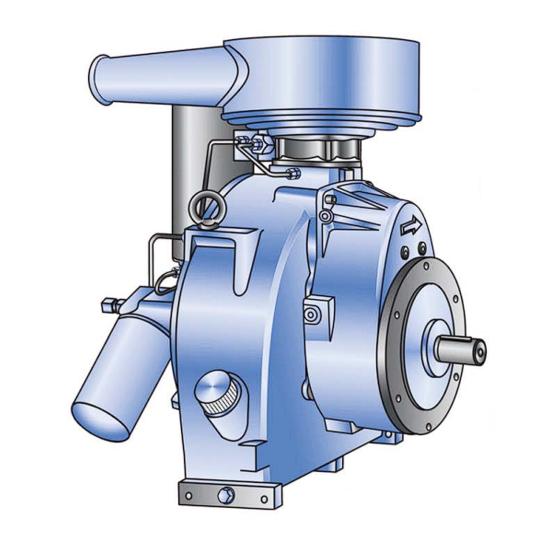
Page 9: Technical Description
Operating Manual - NK 100 Technical Description 3.1 General overview of NK 100 Screw Compressor Compact Module (standard model with electric control unit) 17 16 Figure 3-1 1. Air-oil separating element 2. Intake valve with air filter 3. Maintenance indicator for intake filter (optional) 4. -
Page 10: Flow Diagram Of Nk
The flow diagram shows a schematic view of the 3. Control unit (electric) operating principle and the arrangement of the 3.1 Discharge delay valve (EVV) main components of the NK 100 screw compres- 3.2 Solenoid valve sor module with electrical control unit, regardless 4. Screw compressor of any other equipment. -
Page 11: Starting
Operating Manual - NK 100 3.3.2 Starting 3.3.4 No-load operation When starting the compressor, the solenoid valve When the final pressure in the storage tank is of the control unit is energized. The intake valve 2 reached, the solenoid valve 3.1 is deenergized by is closed by the spring 3-3/4. -
Page 12: Intake Valve For Electric Control Unit
ROTORCOMP VERDICHTER Operating Manual - NK 100 3.4 Intake valve for electric control unit The NK 100 is equipped with an integrated intake valve mounted directly on the compressor hous- ing. Figure 3-3 3.4.1 Installation position A Intake valve opened B Intake valve closed 1. -
Page 13: General Overview Of Nk 100 Screw Compressor Compact Module (Transmission Model With Pneumatic Control Unit)
Operating Manual - NK 100 3.5 General overview of NK 100 Screw Compressor Compact Module (transmission model with pneumatic control unit S3T) Figure 3-5 1. Air-oil separating element 2. Air filter 3. Maintenance indicator for intake filter (optional) 4. Control unit, pneumatic 5. -
Page 14: Flow Diagram Of Nk
The flow diagram shows a schematic view of the 3. Control unit (pneumatic) operating principle and the arrangement of the 3.1 Proportional control valve (positive) main components of the NK 100 screw compres- 3.2 Impulse-pressure relief valve sor module with pneumatic control unit, regardless 4. Screw compressor of any other equipment. -
Page 15: Starting
Operating Manual - NK 100 3.7.2 Starting directly to the oil filter 9 by the thermostat valve. The oil then flows via the oil filter 9 to the various In the startup phase the intake control valve is injection points in the compressor block. -
Page 16: Intake Control Valve For Pneumatic Control Unit
ROTORCOMP VERDICHTER Operating Manual - NK 100 3.8 Intake control valve for pneumatic The NK 100 is equipped with an integrated intake control valve mounted directly on the compressor control unit housing. Figure 3-7 3.8.1 Installation position A Intake valve closed B Intake valve opened 1. -
Page 17: Intake Air Filter
Operating Manual - NK 100 3.9 Intake air filter 3.9.2 Intake filter monitoring • Maintenance indicator, optical (option) • Maintenance indicator, electric (option) The micro dry filter cartridges are recommended as a 1-stage filter with a low filter resistance for standard applications. -
Page 18: Fine Separator
ROTORCOMP VERDICHTER Operating Manual - NK 100 3.10 Fine separator 3.10.1 Oil intake non-return valve Figure 3-11 The oil intake non-return valve 1 prevents flooding of the fine separator cartridge with oil flowing back out of the screw compressor due to the pressure difference in the system when the screw compres- sor system is switched off. -
Page 19: Fine Separator Cartridge
Operating Manual - NK 100 3.10.2 Fine separator cartridge The fine separator cartridge is used to recover the extremely finely distributed residual oil in the form of droplets following the pre-separation. The fine separator cartridge separates virtually the entire residual oil from the compressed air. An... -
Page 20: Minimum Pressure Valve
ROTORCOMP VERDICHTER Operating Manual - NK 100 3.10.3 Minimum pressure valve Figure 3-13 b) Non-return valve It prevents compressed air from flowing back out of the system or the compressed-air reservoir into 1. Non-return valve plate the screw compressor system. As a result, the 2. -
Page 21: Air-Oil Circulation Outside Compressor Module
Operating Manual - NK 100 3.11 Air-oil circulation outside compressor module Figure 3-14 After the oil-air mixture in the fine separator car- tridge has been deoiled, the compressed air flows through the air cooler and from there to the con- sumer. -
Page 22: Oil Filter
The oil filter 1 is screwed onto the bearing cap 2. Figure 3-16 The filter fineness is 20 µm. The NK 100 is equipped with an integrated oil thermostat 1. This is located in the bearing cap The replacement filter has a bypass valve which... -
Page 23: Oil Cooler/Air After-Cooler (Option)
Operating Manual - NK 100 3.12 Oil cooler/air after-cooler (option) Warning: The safety valve must be installed prior to com- With air-cooled screw compressor systems the cir- missioning. culating oil is cooled down from the compressor Operation of the system without a safety valve can... - Page 24 ROTORCOMP VERDICHTER Operating Manual - NK 100 3.16 [en] 09/2008...
-
Page 25: Transport
Operating Manual - NK 100 Transport The deadlines are as follows: a) GERMAN FEDERAL RAILWAY: 4.1 Delivery and packing within 7 days (Paragraph 81/82 of EVO - German Regula- The system is delivered in suitable packing in tions Concerning Carriage by Rail) -
Page 26: Transporting Unpacked System
ROTORCOMP VERDICHTER Operating Manual - NK 100 4.3 Transporting unpacked system 4.4 Transport options The screw compressor can be moved with a crane or with a lift truck or forklift truck when fastened to a transport pallet. Warning: Death or serious injuries due to falling cargo! –... -
Page 27: Installation/Assembly
Operating Manual - NK 100 5.2 Safety precautions for installation Installation/Assembly and assembly 5.1 Connection thread/assembly Caution: 5.1.1 Fastening screws – To lift the compressor module, suitable lifting Female threads are provided on the NK housing equipment must be used which complies with which must be used for fastening. -
Page 28: Installation
ROTORCOMP VERDICHTER Operating Manual - NK 100 5.3 Installation 5.3.2 Drive The compressor module is designed as an alter- native for driving with electric motors, combustion Caution: motors, hydraulic motors, etc. – The system must be installed at a location at... -
Page 29: Belt Drive
If the drive shaft breaks and/or in case of bearing ROTORCOMP recommends installation with an damage, ROTORCOMP can only grant a warranty elastic coupling. The alignment of the motor and if the belt driven is properly designed and exe- compressor module must be carried out according cuted. -
Page 30: Air Outlet
ROTORCOMP VERDICHTER Operating Manual - NK 100 5.6 Air outlet 5.7 Oil cooling The pressure loss at the air outlet due to air after- Note: coolers, fittings, piping, etc.should be as small as The cooler connection lines must be connected possible. -
Page 31: Commissioning
Operating Manual - NK 100 6.2 Checking direction of rotation Commissioning Direction of rotation: 6.1 Preparation for commissioning Standard model rotating to the left (counterclock- The components of the screw compressor are wise) looking at the shaft. carefully checked and tested at the factory. These... -
Page 32: Recommissioning Screw Compressor System
ROTORCOMP VERDICHTER Operating Manual - NK 100 6.4 Recommissioning screw compressor system Screw compressor systems switched off, shut- down or stored for longer than three months can- not be put into operation again until after the fol- lowing measures have been carried out: –... -
Page 33: Maintenance
Operating Manual - NK 100 Maintenance Warning: During all maintenance work: 7.1 Safety precautions ACCIDENT DANGER! The owner must ensure that all maintenance, assembly and repair work is carried out by autho- rized, qualified, specially trained personnel, which has informed itself sufficiently in advance by Note: studying the operating manual in detail. -
Page 34: Oil Level
ROTORCOMP VERDICHTER Operating Manual - NK 100 7.2 Oil level 7.2.2 Oil level check via oil filler opening An important factor for the operating safety of the system is the oil level in the oil reservoir. Warning: The oil level check must be carried out before –... -
Page 35: Oil Change
Operating Manual - NK 100 7.3.2 Oil drain point If necessary, top up oil of the same oil type and • the same brand up to the maximum level. The system should be at operating temperature in this case. Note: The oil filler neck is positioned so that overfilling of the screw compressor system is not possible. -
Page 36: Filling With Oil
ROTORCOMP VERDICHTER Operating Manual - NK 100 7.4.2 Oil filter replacement 7.3.3 Filling with oil Caution: Observe the oil recommendation, see "Lubricants and Operating Materials". Add oil of the same oil type and the same brand. A conversion to another oil type may require flush- ing of the compressor module. -
Page 37: Fine Separator Cartridge
Operating Manual - NK 100 7.5 Fine separator cartridge 7.5.2 Replacing fine separator cartridge Warning: Rotating, pressurized and hot components, DANGER OF INJURY – The unit parts and oil may be over 80°C/176°F; danger of burns! – Wear personal safety equipment! -
Page 38: Intake Air Filter
ROTORCOMP VERDICHTER Operating Manual - NK 100 7.6 Intake air filter 7.6.1 Maintenance intervals According to the specifications of the system man- ufacturer. For the reference values for the screw compressor compact module, see chapter 7.8 "Maintenance intervals". In case of heavily soiled intake air, an earlier... -
Page 39: Maintenance Check Sheet
Operating Manual - NK 100 7.7 Maintenance check sheet • Elapsed time meter reading • Replace air intake filter • Replace oil filter cartridge • Replace oil fine separator cartridge • Retension V-belts • Replace V-belt set • System repair •... -
Page 40: Maintenance Intervals
These must be given priority. It is advisable to conclude a maintenance agreement. The following table provides an over- view of the reference value for the NK 100 screw compressor module. Maintenance intervals Maintenance work... -
Page 41: Lubricants And Operating Materials Maintenance Parts
Operating Manual - NK 100 Lubricants and Note: Operating Materials See the information sheet! Maintenance Parts The requirements placed on the cooling oil in the 8.1 Lubricants and operating materials screw compressor include the following: 8.1.1 Oil recommendation – High resistance to aging RC screw compressors must be operated with an –... -
Page 42: Pressure Dew Point Of Compressed Air
ROTORCOMP VERDICHTER Operating Manual - NK 100 Figure 8-1 Pressure dew point graph 8.1.6 Temperatures 8.1.5 Pressure dew point of compressed air Note: Example: The optimum operating temperatures for the screw compressor system can only be achieved if 1*) Temperature of the intake air is 20°C/68°F,... -
Page 43: Oil Separation
Operating Manual - NK 100 8.1.9 Oil separation The fine oil separation becomes poorer in the upper area with an increasing compressor outlet temperature. 8.1.10 Multigrade oil The use of multigrade oils can cause problems in the long run, as "viscosity improvers" used are destroyed over time. - Page 44 ROTORCOMP VERDICHTER Operating Manual - NK 100 [en] 09/2008...
-
Page 45: Technical Data And Tightening Torques
Operating Manual - NK 100 Technical Data and Tightening Torques 9.1 Technical data Screw compressor model NK 100 NK 100 G Max. operating gauge pressure. Max. delivered quantity according to DIN 1945 up to /min Required output up to (full load without fan) Max. - Page 46 ROTORCOMP VERDICHTER Operating Manual - NK 100 9.2 Tightening torques Caution: The maximum permissible tightening torque for all screw connections may not be exceeded. VDI 2230 Unless otherwise specified, the following torques must be used. Always tighten screws/bolts with a torque wrench.
-
Page 47: Troubleshooting
Operating Manual - NK 100 10 Troubleshooting Fault Possible cause Remedy See chapter Incorrect direction of Phases reversed Reconnect 2 supply lines rotation System difficult to start Motor output insufficient Check Drive gear ratio "too fast" Check Star-delta switchover incorrect... - Page 48 ROTORCOMP VERDICHTER Operating Manual - NK 100 Fault Possible cause Remedy See chapter Safety valve blows off Safety valve defective Replace safety valve Fine separator cartridge Replace cartridge 7.5.2 soiled System does not switch off Check solenoid valve automatically Control valve operates...
- Page 49 Operating Manual - NK 100 Fault Possible cause Remedy See chapter Control valve does not System leaky Check system and seal off open if necessary Solenoid valve/electrical Check and replace parts system, bypass valve, if necessary piston gasket, minimum pressure valve do not...
- Page 50 ROTORCOMP VERDICHTER Operating Manual - NK 100 10.4 [en] 09/2008...
- Page 52 ROTORCOMP VERDICHTER GmbH Industriestraße 9 82110 Germering Germany Tel.: +49 89 724 09-0 Fax: +49 89 724 09-38 info@rotorcomp.de www.rotorcomp.de A member of BAUER GROUP...
Need help?
Do you have a question about the NK 100 and is the answer not in the manual?
Questions and answers