Table of Contents
Advertisement
420-0024-01UK
1
st
PRINTING
Sega Amusements International Limited.
42 Barwell Business Park, Leatherhead Road, Chessington, Surrey, KT9 2NY. United Kingdom.
Telephone: +44 (0) 208 391 8090
Facsimile:
+44 (0) 208 391 8089
email: sales@segaarcade.com
Web: http://www.segaarcade.com
© SEGA
IMPORTANT
• Before using this product, read this manual carefully to understand the
contents herein stated.
• After reading this manual, be sure to keep it near the product or in a
convenient place for easy reference when necessary.
Advertisement
Table of Contents

Related Manuals for Sega SONIC DASH EXTREME


Summary of Contents for Sega SONIC DASH EXTREME
- Page 1 420-0024-01UK PRINTING Sega Amusements International Limited. 42 Barwell Business Park, Leatherhead Road, Chessington, Surrey, KT9 2NY. United Kingdom. Telephone: +44 (0) 208 391 8090 Facsimile: +44 (0) 208 391 8089 email: sales@segaarcade.com Web: http://www.segaarcade.com © SEGA IMPORTANT • Before using this product, read this manual carefully to understand the contents herein stated.
- Page 2 BEFORE USING THE PRODUCT, BE SURE TO READ THE FOLLOWING: To maintain safety: To ensure the safe operation of this product, be sure to read the following before usage. The following instructions are intended for the users, operators and the personnel in charge of the operation of the product.
- Page 3 SEGA shall not be held responsible for any accidents, compensation for damage to a third party, resulting from the specifi cations not designated by SEGA.
-
Page 4: Introduction
This manual is intended to provide detailed descriptions together with all necessary information covering the general operation of electronic assemblies, electro-mechanicals, servicing control, spare parts, etc. for the product, "SONIC DASH EXTREME" Arcade This manual is intended for the owners, personnel managers in charge of operation of this product. - Page 5 Defi nition of 'Site Maintenance Personnel or Other Qualifi ed Individuals Defi nition of 'Site Maintenance Personnel or Other Qualifi ed Individuals Procedures not described in this manual or marked as ‘to be carried out by site maintenance personnel or other qualifi ed professionals’ should not be carried out by personnel without the necessary skill or technology.
- Page 6 Electrical and Electronic Equipment to take back products at the end of their useful life. Sega Amusements Europe Ltd accepts its responsibility to fi nance the cost of treatment and recovery of redundant WEEE in the United Kingdom in accordance with the specifi ed WEEE recycling requirements.
- Page 7 By accepting this agreement or using the software, you agree to all of these terms and consent to the transmission of certain information for Internet-based features of the software. If you do not accept and comply with these terms, you may not use the software or features. Instead, you may contact SEGA to determine its return policy for a refund or credit under that policy.
- Page 8 Internet-based features available to you, in accordance with the Windows 8 Privacy Statement, at go.microsoft.com/fwlink/?LinkId=190175. Some Internet-based features may be delivered at a later date via Microsoft’s Windows Update service—if, for example, you acquire an application that relies on one of those services. SEGA may have elected to turn on one or more of the follow- ing features in the licensed device.
- Page 9 15. REFUND PROCEDURES If you are seeking a refund, contact SEGA to determine its return policy for a refund or credit. You must comply with that policy, which might require you to return the software with the entire licensed device on which the software is installed for a refund.
-
Page 11: Table Of Contents
TABLE OF CONTENTS INTRODUCTION HANDLING PRECAUTIONS PRECAUTIONS REGARDING INSTALLATION PRECAUTIONS REGARDING OPERATION PART DESCRIPTIONS ACCESSORIES ASSEMBLY AND INSTALLATION 6-1 INSTALLING THE CABINET 6-2 FIXATION TO SITE 6-3 POWER SUPPLY AND OTHER CONNECTIONS 6-4 TURNING ON THE POWER 6-5 CONFIRMATION OF ASSEMBLY 6-6 APPLYING WARNING LABELS (EPILEPTIFORM SEIZURES) PRECAUTIONS WHEN MOVING THE MACHINE 7-1 PRECAUTIONS WHEN MOVING FROM SITE... - Page 12 CONTROLLER UNIT(S) 10-1 REMOVING THE CONTROLLER GRAPHICS DISPLAY 11-1 SAFETY PRECAUTIONS WHEN HANDLING THE MONITOR COIN HANDLING 12-1 CLEANING THE COIN SELECTOR 12-2 FAULT FINDING 12-3 ADJUSTING THE PRICE OF PLAY (EXCEL) LAMPS AND LIGHTING 13-1 COIN DOOR LAMP 13-2 BILLBOARD LED LIGHTING 13-3 HALF HOOP LED LIGHTING 13-4 FULL HOOP LED LIGHTING PERIODIC INSPECTION...
- Page 13 This page intentially left blank...
-
Page 14: Handling Precautions
- SEGA shall not be held responsible for damage, compensation for damage to a third party, caused by specifi cation changes not designated by SEGA. - Page 15 Some parts are not designed and manufactured specifically for this game machine. The manufacturers may discontinue, or change the specifi cations of such general-purpose parts. If this is the case, SEGA cannot repair or replace a failed game machine whether or not a warranty period has expired.
- Page 16 CONCERNING THE STICKER DISPLAY This SEGA product has stickers attached describing the product manufacture No. (Serial No.) and Electrical Specifi cations. It also has a Sticker describing where to contact for repair and for purchasing parts. When inquiring about or asking for repairs, mention the Serial No. and Name of Machine indicated on the Sticker.
-
Page 17: Precautions Regarding Installation
PRECAUTIONS REGARDING INSTALLATION • This product is an indoor game machine. Do not install it outside. Even indoors, avoid installing in places mentioned below so as not to cause a fi re, electric shock, injury and/or malfunction. • Places subject to rain or water leakage, or places subject to high humidity in the proximity of an indoor swimming pool and/or shower, etc. - Page 18 Securing a safe area for operation as described in this manual will ensure safe operation for players and observers. SEGA shall not be held responsible for damage or compensation for damage to a third party, resulting from the failure to observe this instruction.
- Page 19 To install this product, the entrance must be at least 1.2m in width and 2.1 m in height (without Assy Billboard) and 2.7m (with Assy Billboard). Do not attempt to push/pull whilst holding onto the Assy Billboard. This may result in part damage and or personal injury.
-
Page 20: Precautions Regarding Operation
PRECAUTIONS REGARDING OPERATION To avoid injury and trouble, be sure to pay attention to the behavior of visitors and players. In order to avoid accidents, check the following before starting the operation: • To ensure maximum safety for the players and the customers, ensure that where the product is operated has suffi... - Page 21 • To avoid electric shock, ensure that all covers and panels are undamaged and fi tted. Do not operate with covers removed. • To avoid electric shock, short circuit and/or parts damage, do not put the following items on or in the periphery of the product. Flower vases, flowerpots, cups, water tanks, cosmetics, and receptacles/ containers/vessels containing chemicals and water.
- Page 22 DURING OPERATION (PAYING ATTENTION TO CUSTOMERS) To avoid injury and trouble, be sure to constantly give careful attention to the behavior and manner of the visitors and players. • For safety reasons, do not allow any of the following people to play the game. Those who have high blood pressure or a heart problem.
-
Page 23: Part Descriptions
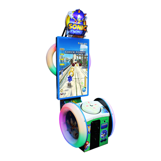
PART DESCRIPTIONS Billboard Half Hoop L Half Hoop R 55” LED Screen Speakers Dash Button Full Hoop L Controller Stabilisers Double Framed Mini Door (DFMD) Full Hoop R STS Secure Door Ticket Door... -
Page 24: Accessories
ACCESSORIES Confi rm that the accessories listed in the table below are present when setting up the product. Accessories marked “Spare” in the note column are consumable items but included as spares. KEY MASTER DESCRIPTION: OWNER’S MANUAL 220-5575-01UK (2) Part No. (Qty.): 420-0024-01UK(1) For operating/closing the doors Parts not labeled with part numbers are as yet... -
Page 25: Assembly And Installation
ASSEMBLY AND INSTALLATION • Perform assembly work by following the procedure herein stated. Failure to comply with the instructions can cause electric shock. • Perform assembly as per this manual. Since this is a complex machine, incorrect assembling can cause an electric shock, machine damage and/or improper functioning as per specifi... -
Page 26: Installing The Cabinet
6-1 INSTALLING THE CABINET • To perform work safely and securely, be sure to prepare a step which is in a safe and stable condition. Performing work without using a step may lead to injury of damage to components. Tools required for installation: Allen Key (M8) (Not Supplied) - Attaching ASSY BILLBOARD to cabinet - Attaching BKT CABI LOWER... - Page 27 6-1-1 INSTALLING THE ASSY BILLBOARD The Billboard is separately wrapped along with the cabinet and needs to be applied prior install.. Assy Billboard - SND 0500UK Using a Step Ladder or Stool, raise the ASSY BILLBOARD and align with the fi xing holes at the top of the cabinet.
- Page 28 Once in position, secure the ASSY BILLBOARD at the rear of the cabinet using (6) M8x25 SKT CAP Screws and washers (029-B00825-0B/060-S00800-0B/068-852216-0B) M8 WSHR SPR BLK M8 WSHR 22OD FLT BLK 060-S00800-0B 068-852216-0B M8x20 Socket Cap Screws 029-B00825-0B Fixing locations Fit and secure the remaining 2 fi...
- Page 29 • Due the nature and the design of the cabinet it is IMPORTANT that the CABINET LOWER BRACKETS are fi tted to both sides of the cabinet. These brackets, when fi tted provide the cabinet with extra stability. Failing to apply these brackets to the cabinet may render the cabinet unstable.
-
Page 30: Fixation To Site
6-2 FIXATION TO SITE • Make sure that all the adjusters contact the fl oor. Otherwise the cabinet could move, causing an accident. • Provide a ventilation space at least 20cm wide behind the cabinet. There are ventilation holes on the back of the cabinet. Do not block the ventilation holes. Doing so could trap heat inside resulting in fi... - Page 31 • Provide a ventilation space at least 20cm wide behind the cabinet. There are ventilation holes on the back of the cabinet. Do not block the ventilation holes. Doing so could trap heat inside resulting in fi re. It could also result in equipment damage or cause parts to become exhausted prematurely.
-
Page 32: Power Supply And Other Connections
6-3 POWER SUPPLY AND OTHER CONNECTIONS • Use the power supply equipped with an earth leakage breaker. Use of power supply without such a breaker could result in fi re if there is a current leakage. • Have available a securely grounded indoor ground terminal. Without proper grounding, customers could be electrocuted and product operations might not always be stable. -
Page 33: Turning On The Power
Set the main switch of the AC unit to ON and engage the power. When you turn on the power, the billboard LED lights will come on. After the SEGA LOGO start up screen is displayed on the LCD screen, the Advertise (Attract) Mode will start. - Page 34 COMPONENTS WHICH CHANGE STATE WHEN POWER IS APPLIED Billboard illumination SEGA logo Attract Mode - Game Half Hoop Illumination Half Hoop Illumination Audio output Controller Illumination Full Hoop Illumination Full Hoop Illumination Coin Door Lamp...
-
Page 35: Confirmation Of Assembly
6-5 CONFIRMATION OF ASSEMBLY In the test mode, ascertain that the assembly has been made correctly and IC Board is satisfactory. In the test mode, perform the following test: (refer to chapter 9). 9-13 INPUT TEST This menu is used to test the system inputs such as steering, pedals and buttons. To implement the test, press each device that is listed and check the results on screen. -
Page 36: Applying Warning Labels (Epileptiform Seizures)
6-6 APPLYING WARNING LABELS (EPILEPTIFORM SEIZURES) • The operator MUST apply the Epileptiform Seizure Label to this product. Failing to apply this label may result in the player/observer suffering from a photosensitive seizure. Warning the potential player/ observer of this before the start of a game may prevent such accidents. -
Page 37: Precautions When Moving The Machine
PRECAUTIONS WHEN MOVING THE MACHINE • Always disconnect the power cable before moving the product. If it is moved with the power cable connected, the cable could be damaged, causing fi re or electric shock. • To move the unit over the floor, pull in the adjustors and have the casters contact the floor. -
Page 38: Precautions When Moving From Site
7-1 PRECAUTIONS WHEN MOVING FROM SITE • When moving the cabinet, do not grip or push the Billboard Plate. Doing so could deform or damage the part. • If moving through a door or place with a low ceiling such as an elevator, you should take apart the billboard and billboard plate. -
Page 39: Game Description
GAME DESCRIPTION 8-1 HOW TO PLAY GAME INTRODUCTION This machine has two game modes. One is “Ticket Redemption, the other is “Amusement only” (Fun for play, no tickets). (Redemption /Amusement mode) 1. After the coins are inserted, available credits will display at the bottom of the screen. 2. - Page 40 Arcade mode Basic Rules Player’s target is to reach goal. For that, some actions are required. Redemption/Arcade 1. Player’s character has limited lives for playing game. * 2. Character automatically go forward when this game starts 3. Reach to the goal area by controlling the character. 4.
- Page 41 Basic Control Take action with D-pad and button not only for avoiding crashing but also attacking the creatures. 1. Player can use a D-Pad and a Dash button for some action. 2. Each direction on D-Pad means take action like below. Up:Jump Left:Move to Left Right:Move to Right...
- Page 42 Mini Game ・As the game continues, There is an area where the character automatically jump to sky. ・This is called a “Mini Game” where "ACTION!” will take place. ・A players have to turn D-Pad directions on screen information within limited time. ・If the player succeed in action, he/she can gain extra score bonus.
- Page 43 Summary of Redemption mode. Flow 1. A player will select his/her character.* 2. After character selected, each stage will automatically be selected. *If you set mode setting “SKIP SELECT SEQUENCE ON”, a player character is automatically selected. 3.Game starts 4. The Player can get tickets with going through check points and collecting rings. 5.
- Page 44 Summary of Arcade mode. Flow 1. A player will select his/her character.* 2. After a character is selected, the player will choose a diffi culty and stage. 3. Game starts 4. This mode has time limits. If time is over, it means game over. 5.
- Page 45 Ranking Amusement mode has daily ranking system. Players can join a daily top 10 ranking where he/she can enter his/her name within 3 characters. [Name entry] -Closing credits If a player defeats Eggman and also gain the top score of the day, closing credit will show on the screen.
-
Page 46: Explanation Of Test And Data Display
EXPLANATION OF TEST AND DATA DISPLAY Perform tests and data checks periodically by manipulating the TEST Button and SERVICE Button in the cabinet. Follow the instructions in this chapter to conduct checks when the game machine is fi rst installed, when money is being collected, or when the game machine does not operate properly. -
Page 47: Switch Unit And Coin Meter
9-1 SWITCH UNIT AND COIN METER. Never touch places other than those specifi ed. Touching places not specifi ed can cause electric shock and short circuit accidents. • Adjust the sound to the optimum volume, taking into consideration the environmental requirements of the installation location. •... -
Page 48: System Test Mode
9-2 SYSTEM TEST MODE The details of changes to Test Mode settings are saved when you exit from each Test Mode by selecting EXIT. Be careful because if the power is turned off before that point, changes to the settings will be lost. -
Page 50: System Information
9-3 SYSTEM INFORMATION... -
Page 52: Storage Information
9-4 STORAGE INFORMATION... -
Page 54: Jvs Test
9-5 JVS TEST... - Page 56 JVS INPUT TEST...
-
Page 57: Monitor Test
9-6 MONITOR TEST... -
Page 58: Speaker Test
9-7 SPEAKER TEST... -
Page 59: Coin Assignments
9-8 COIN ASSIGNMENTS... - Page 62 DETAIL SETTING...
- Page 64 GAME COST SETTINGS...
-
Page 65: Clock Setting
9-9 CLOCK SETTING... -
Page 67: Network Setting
9-10 NETWORK SETTING... - Page 68 MAIN NETWORK...
- Page 70 NETWORK TEST...
-
Page 71: Game Test Menu
9-11 GAME TEST MENU GAME TEST MENU Press test button to enter GAME TEST MENU screen. ■Control - Use the SERVICE Button to move the cursor to the desired test item. - Press the TEST Button to confi rm selection of the item. - Select EXIT and press the TEST Button to return to the SYSTEM TEST MODE screen. -
Page 72: Bookkeeping
9-12 BOOKKEEPING BOOKKEEPING(1/4) Each game record can be viewed. ■Control - Press the TEST Button to move to BOOKKEEPING 2/4 screen. ■Menu Item COIN1 Number of coins inserted in coin chute 1. COIN2 Number of coins inserted in coin chute 2. TOTAL COINS Total Number of coins inserted in coin chute. - Page 73 BOOKKEEPING(2/4)**Video Redemption *It has difference text between Video Redemption mode and Amusement only mode for Bookkeeping 2/4. ■Control - Press the TEST Button to move to BOOKKEEPING 2/4 screen. ■ Menu Item NUMBER OF GAMES Total number of games played by a player. TOTAL TIME Amount of time the cabinet has been in operation.
- Page 74 BOOKKEEPING(2/4) *Amusement only mode ■Control - Press the TEST Button to move to BOOKKEEPING 3/4 screen. ■ Menu Item NUMBER OF GAMES Total number of games played by a player. TOTAL TIME Amount of time the cabinet has been in operation. PLAY TIME Amount of time the game has been played.
- Page 75 BOOKKEEPING(3/4) *It is for Video Redemption mode only. On the Amusement only mode, text color changes to gray. ■Control - Press the TEST Button to move to BOOKKEEPING 4/4 screen. ■ Menu Item TOTAL TICKET OUT Total number of paid tickets.. BONUS WINS Amount of time of Super Bonus BONUS TICKET WINS...
- Page 76 BOOKKEEPING(4/4) ■Control - Press the TEST Button to return to GAME TEST MODE screen. ■Menu Item Play time will be recorded into different lines by 30 seconds intervals. All play times over 5 minutes are written into the line OVER 5M00S.
-
Page 77: Input Test
9-13 INPUT TEST INPUT TEST Look up the status of each input devices. ■Control - Press TEST button and SERVICE button at the same time to return to GAME TEST MODE screen. - When the corresponding menu items displays from “OFF” to “ON” or corresponding data reacts to the ac- tion, the device is then functional. -
Page 78: Output Test
9-14 OUTPUT TEST OUTPUT TEST Test all the output devices utilized in game. Please test all the output devices in regular term. ■Control - Use the SERVICE Button to move the cursor to the desired test item. - Press the TEST Button to confi rm selection of the item. - Select EXIT and press the TEST Button to return to GAME TEST MODE screen. -
Page 79: Ticket Test
9-15 TICKET TEST TICKET DISPENSER TEST Test all the ticket vending devices utilized in game. ■Control - Use the SERVICE Button to move the cursor to the desired test item. - Press the TEST Button to confi rm selection of the item. - Select EXIT and press the TEST Button to return to GAME TEST MODE screen. -
Page 80: Game Assignments
9-16 GAME ASSIGNMENTS GAME ASSIGNMENTS Game setting confi guration. The gray color means not select. It depends on each mode. ■Control - Use the SERVICE Button to move the cursor to the desired test item. - Press the TEST Button to confi rm selection of the item. - Select EXIT and press the TEST Button to return to the GAME TEST MODE screen. - Page 81 Changing game mode. When game mode changes, below screen will be shown. ■Control *Press SERVICE button to select menu item. *Select “YES (CLEAR) and press TEST button to clear all backup data. When “COMPLETED” is displayed, press TEST button again and return to GAME TEST MODE screen. ...
-
Page 82: Ticket Settings
9-17 TICKET SETTINGS ATTENTION!!! We recommend BACKUP DATA CLEAR when the Ticket payout setting and setting that related to Payout rate were changed because some time cause confusion of BOOKKEEPING data. DIFFICULTY SETTINGS ■Control - Use the SERVICE Button to move the cursor to the desired test item. - Press the TEST Button to confi... -
Page 83: Bonus Settings
9-18 BONUS SETTINGS Ticket bonus setting. ■Control - Use the SERVICE Button to move the cursor to the desired test item. - Press the TEST Button to confi rm selection of the item. - Select EXIT and press the TEST Button to return to the TICKET SETTING screen. ■Menu Item SUPER BONUS STAGE If set to ON, the Bonus stage appears after a character pass the goal. -
Page 84: Difficulty Settings
9-19 DIFFICULTY SETTINGS DIFFICULTY SETTING Ticket OUTPUT setting. DIFFICULTY SETTINGS RESET DIFFICULTY SETTINGS ■Control - Use the SERVICE Button to move the cursor to the desired test item. - Press the TEST Button to confi rm selection of the item. - Select EXIT and press the TEST Button to return to the TICKET SETTING screen. -
Page 85: Backup Data Clear
9-20 BACKUP DATA CLEAR BACKUP DATA CLEAR Clear all game records ■Control *Press SERVICE button to select menu item. *Select “YES (CLEAR) and press TEST button to clear all backup data. When “COMPLETED” is dis- played, press TEST button again and return to GAME TEST MODE screen. ***Select “NO (CANCEL)”... -
Page 86: Ticket Error
9-21 TICKET ERROR Ticket Dispenser Error EMPTY ERROR This message will be displayed immediately in game mode if the tickets are not fi lled and set in ticket BIN & Dispenser. Fill tickets and press Ticket Release Switch to back normal. -
Page 87: Controller Unit(S)
CONTROLLER UNIT(S) • When working with the product, be sure to turn the power off. Working with the power on may cause an electric shock or short circuit. • Be careful not to damage the wires. Damaged wires may cause an electric shock, short circuit or present a risk of fi... -
Page 88: Removing The Controller
Be sure to perform TEST in the INPUT ASSIGNMENTS in the Game Test Mode after replacing or adjusting switches. 10-1 REMOVING THE CONTROLLER A 5 mm hexagonal wrench is required for the following procedure. Turn off the power. Remove the 8 hexagon socket button head screws from both sides of the Control Panel’s front and back. Gentle lift the Control Panel Cover and place to one side. - Page 89 Locate the (6) fi xings, 3 positioned either side of the D-Pad and remove. Once all (6) fi xings have been removed, carefully lift the D-Pad. Once the D-pad has cleared the mechanics of the Controller, carefully overturn the D-Pad cover to locate the Button and Button harness.
- Page 90 BULB/LED REPLACEMENT • Be sure to replace the lamp like for like. Replacing the lamp or LED with a different type/value may cause malfunction, electrical component failure or even a fi re hazard. • Take care when replacing 'Glass' bulbs. The integrity of a glass bulb may be impaired.
-
Page 91: Graphics Display
GRAPHICS DISPLAY 11-1 SAFETY PRECAUTIONS WHEN HANDLING THE MONITOR Responding to breakdown or abnormality ● If smoke or a strange odor appears, immediately unplug the power cable from the power source. Continuing to use the product may cause a fi re or an electric shock. Ensure that smoke is no longer emitted, and contact the point of purchase. - Page 92 11-2 CLEANING THE SCREEN SURFACE ● Use a soft, dry cloth (fl annel-type) to wipe away dirt. Do not use materials such as coarse mesh gauze. ● Alcohol (ethanol) is the recommended solvent for removing dirt. When using a cleaning agent, follow the precautions below. Dilute neutral cleaning agents for home use with water.
- Page 93 11-3 ADJUSTMENT METHOD All adjustment values are set accurately at the time of shipping from the factory. Do not readjust these values needlessly or apply adjustments not specifi ed in this manual. The display may not appear properly if the values are incorrect.
- Page 94 11-3 ADJUSTMENT METHOD Button Names and Functions 11-3 Fig. 03 MENU: Turn the Picture Menu display ON and OFF. SELECT: Gains entry to the Item selected in the menu. (Highlights in Yellow when selected) Exits the Item adustment. Any changes made during this operation are actioned.
- Page 95 11-3 ADJUSTMENT METHOD On-Screen Display (OSD) Press the MENU Button while the OSD is not displayed to bring up the Picture Menu. On the Picture Menu, it is possible to perform various screen adjustments. 11-3 Fig. 04 Use the UP and DOWN Buttons to move the ‘Black Bar’to the item you want to adjust. After selecting the desired item, pressing the SELECT Button will extend the MENU Screen and allow adjustments to be changed.
- Page 96 11-3 ADJUSTMENT METHOD On-Screen Display (OSD) <continued> 11-3 Fig. 06 Available Settings (Selects Operation Mode)) Selection availble - 6500K - 9300K - USER BRIGHTNESS (Adjust Brightness) Adjust screen Brightness. - Values: 0 - 100 (0” being the darkest setting, and “100” being the brightest) CONTRAST (Adjust Contrast) Adjust Contrast level.
-
Page 97: Coin Handling
COIN HANDLING Handling the Coin Jam If the coin is not rejected when the REJECT button is pressed, open the coin chute door and open the selector gate. After removing the jammed coin, put a normal coin in and check to see that the selector correctly functions. - Page 98 CLEANING THE COIN SELECTOR (MECHANICAL). Remove and clean smears by using a soft cloth dipped in water or diluted chemical detergent and then squeezed dry. Remove the CRADLE.. When removing the retaining ring (E ring) be very careful so as not to bend the rotary shaft.
- Page 99 CLEANING THE COIN SELECTOR (SR3/NRI) <continued> Remove and clean smears by using a damp soft cloth dipped in water. DO NOT use any diluted chemical detergent or cleansing agent as this will impair the workings of the component. GATE Open the reject gate to gain access to the rundown path.
-
Page 100: Fault Finding
12-2 FAULT FINDING Fault Finding The following information is presented for customers’ guidance in rectifying a fault but does not cover all possible causes. All acceptors with electronic faults should be returned to an approved service centre for repair. SYMPTOM INVESTIGATE POSSIBLE CAUSE Poor Contact... -
Page 101: Adjusting The Price Of Play (Excel)
12-3 ADJUSTING THE PRICE OF PLAY (EXCEL) ● The price of play is determined by the confi guration of switches located on either an EXCEL board or VTS board. The type of board used is determined by product location. Switch settings for both types of board remain the same. This product comes equipped with a Money Controls SR3 Coin Acceptor. - Page 102 REGIONAL AND ACCEPTOR SETTINGS (SW3)
- Page 103 STERLING PRICE OF PLAY SETTINGS (SW1)
- Page 104 EURO PRICE OF PLAY SETTINGS (SW1)
-
Page 105: Lamps And Lighting
LAMPS AND LIGHTING • When working with the product, be sure to turn the power off. Working with the power on may cause an electric shock or short circuit. • You may get burned by a hot fl uorescent lamp or other lamps. Pay full attention to the lamps when performing the work. -
Page 106: Billboard Led Lighting
13-2 BILLBOARD LED LIGHTING THIS WORK ON TOP OF THE CABINET, SHOULD NOT BE UNDERTAKEN WITHOUT THE USE OF A SUITABLE STEP OR FOOTSTOOL. MAKE SURE THAT THE MAIN SUPPLY VOLTAGE TO THE MACHINE IS SWITCHED OFF AND UNPLUGGED BEFORE ATTEMPTING TO CARRY OUT THIS WORK The Billboard LED’s are located between the back section of the Billboard and the front Artwork, before attempting to change the Tube, TURN THE POWER OFF. - Page 107 Using a sharp handled blade, carefully strip back the protective sleeving to reveal the solder joint. Using a Soldering Iron carefully unsolder the harness from the defective LED strip. SLEEVE Once the harness has been successfully removed from the LED strip, resolder it to the replacement LED making note of the polarity.
-
Page 108: Half Hoop Led Lighting
13-3 HALF HOOP LED LIGHTING THIS WORK ON TOP OF THE CABINET, SHOULD NOT BE UNDERTAKEN WITHOUT THE USE OF A SUITABLE STEP OR FOOTSTOOL. MAKE SURE THAT THE MAIN SUPPLY VOLTAGE TO THE MACHINE IS SWITCHED OFF BEFORE ATTEMPTING TO CARRY OUT THIS WORK To remove the HALF HOOP Outer cover, locate and remove the (7) M4x12 SKT BH PAS (029-B00412). - Page 109 Replace the defective LED board with that of the same type. HALF RING LED BD (601-13101-001) Half Ring LED 601-13101-001 When replacing, take precautions not to overtighten. Reconnect the harnesses and refi t the Outer Ring Cover using the fi xings removed in step 1,...
-
Page 110: Full Hoop Led Lighting
13-4 FULL HOOP LED LIGHTING MAKE SURE THAT THE MAIN SUPPLY VOLTAGE TO THE MACHINE IS SWITCHED OFF BEFORE ATTEMPTING TO CARRY OUT THIS WORK To remove the FULL HOOP Outer cover, locate and remove the (9) M4x12 SKT BH PAS (029-B00412). Remove (5) from the outer edge and (4) from the inner edge. - Page 111 With the COVER SIDE RING removed, locate the suspect LED BD to replace and disconnect the connectors at both ends. Once the Cover has been removed and the harness disconnected, remove the (4) M3x16 SKT BH BLK fi xings which secure the LED Bd to the metal retaining brackets. RING LED 601-13101-002 Fixing points (4)
-
Page 112: Periodic Inspection
PERIODIC INSPECTION The items listed below require periodic check and maintenance to retain the performance of this machine and to ensure safe business operation. When handling the controller, the player will be in direct contact with it. In order to always allow the player to enjoy the game, be sure to clean it regularly. - Page 113 Cleaning the Cabinet Surfaces When the cabinet surfaces are badly soiled, remove stains with a soft cloth dipped in water or diluted (with water) chemical detergent and squeezed dry. To avoid damaging surface fi nish, do not use such solvents as thinner, benzine, etc.
-
Page 114: Troubleshooting
TROUBLESHOOTING 15-1 TROUBLESHOOTING (WHEN NO ERROR MESSAGE IS SHOWN) • In order to prevent electric shock and short circuit, be sure to turn power off before performing work. • Be careful so as not to damage wirings. Damaged wiring can cause electric shock or short circuit. - Page 115 Sound is not emitted. Sound volume adjustment is not Adjust the Switch Unit’s sound correct adjustment volume. Faulty connections for various Check the connections for the game connectors board, amp, speakers and Volume connectors Malfunctioning BD, amp and speaker Perform Sound Test. Sounds are emitted and Faulty connections for the visual Check the connections for the monitor...
- Page 116 Replacing Fuses • In case fuse replacements other than those stated in this manual are necessary, contact where you purchased the product from for inquiries regarding this matter. • In order to prevent an electric shock, be sure to turn power off and unplug from the socket outlet before performing work by touching the internal parts of the product.
-
Page 117: Game Board (Nusx)
GAME BOARD (NuSX) ● When working with the product, be sure to turn the power off. Working with the power on may cause an electric shock or short circuit. ● Be careful not to damage the wires. Damaged wires may cause an electric shock, short circuit or present a risk of fi... -
Page 118: Handling Precautions
fi re due to short circuit, etc. Ensure the IC Board surfaces are always kept clean. ● Always follow the usage conditions from SEGA as well as the usage conditions for the cabinet you are using for NuSX. Failure to do so may cause an overheating and fi... -
Page 119: Game Board (Nusx) - Location
16-2 GAME BOARD (NuSX) - LOCATION ● When returning the game board after making repairs or replacements, make sure that there are no errors in the connection of connectors. Erroneous connections can lead to electrical shock, short circuits or fi res. ●... -
Page 120: Nusx Cleaning
16-3 NuSX CLEANING • If either ERROR 0090 or ERROR0091 are displayed then the Game bd must be cleaned and made free from dust particles. These ERRORs have been put in place to prevent the Game bd from overheating in not cleaned on a regularly basis. -
Page 121: Replacing The Lithium Battery
CPU and other electronic components. If anything outside the normal operation occurs be ready to remove power. • Please take care when reconnect harnesses. Make sure connectors are fi rmly connected. If damage occurs during reconnecting then please contact your local SEGA offi ce for replacement. - Page 122 ● Make sure you do not damage the printed board and wires. Such damage can lead to electric shock, short circuit and fi re hazard. ● To prevent overheating, explosion, or fi re: - Do not recharge, disassemble, heat, incinerate, or short the battery. - Do not allow the battery to come into direct contact with metallic objects or other batteries.
- Page 123 AM Expansion Bd may no loger be able to save the backup data. Please replace the battery within this time. If within the 5 years of normal operation the battery needs replacing, please contact your local Sega Service centre as it may be considered that some abnormalities may have occured within the Game Bd.
- Page 124 To remove the battery from the Expansion Bd, using your fi nger nad thumb, lift up the battery to enable you to grasp it from the top. Take note of the battery orientation. The (+) positive is facing outside. Lithium Battery 401-0054 401-0054 After the new battery has been replaced, please refer to these instructions and apply them in reverse order to...
- Page 125 It is important that the Lithium battery is replaced immediately. If a time of 100 seconds or more lapses then it is possible that a CMOS Checksum error may occur. You may receive an error in the display. If is occurs then please contact your local Sega Service center as described within this manual. Lithium Battery...
-
Page 126: Nusx Connections
16-5 NuSX CONNECTIONS The NuSX GAme Bd has various connections which are required by this game and therefore need to be connected for the game to function correctly. Security Key Chip Video Output Test Switch Service Switch COM 2 USB to JVS I/O Bd LED Controller Audio Out 3.5mm Jack to Audio Amp... -
Page 127: Error Codes
16-6 ERROR CODES The NuSX is equipped to display various errors on-screen to help solve any problems. If an error is displayed, the game cannot be used. Use the following table of causes and countermeasures to solve the problem. If the problem cannot be resolved, contact the offi ce listed inthe manual or the Point-of-purchase. -
Page 136: Design Related Parts
DESIGN RELATED PARTS For the warning display stickers, refer to Section 1. -
Page 137: Parts List
PARTS LIST ASSY TOP SONIC DASH STRUCTURE... - Page 138 1 ASSY TOP SONIC DASH (SND-0000UK) (D-1/1) ITEM PART NUMBER DESCRIPTION SND-1000XUK ASSY MAIN CABI 55" LED 421-7988-91UK STICKER SERIAL NUMBER UK 440-WS0100UK LABEL WARNING FORK HERE 440-DS0010UK LABEL DANGER HI VOLT LB1046 LABEL TESTED FOR ELEC. SAFETY LB1130 LABEL WEEE WHEELIE BIN 440-CS0186-01UK STICKER CAUTION EPILEPSY 440-CS0010UK...
- Page 139 2 ASSY SW UNIT DOUBLE METER (SND-0302UK) (D-1/1) ITEM PART NUMBER DESCRIPTION ***1 SSR-0321UK SW BRKT DOUBLE METER ***2 LB1152 STICKER VTS ***101 838-14548-01AUK SW & VOL CTL BD ***102 280-L00706-PM STANDOFF 6.4MM HOLE PM ***103 EP1380-01 CREDIT BOARD EXCEL ***104 220-5643UK COIN METER SMALL 12V...
- Page 140 3 ASSY HEADER (SND-0500UK) (D-1/1) ITEM PART NUMBER DESCRIPTION ***1 SND-0511XUK BRKT SECURE HEADER REAR SUPP ***3 SND-0513XUK BRKT SECURE HEADER REAR ***5 SND-0505UK PNL HEADER FRONT ***6 SND-0506UK PNL HEADER REAR ***7 SND-0517XUK PNL HEADER BACKBOARD ***102 280-L01030-0S STANDOFF 10OD 5.2ID 30L ***103 601-0460 CABLE TIE NYLON 100MM...
- Page 141 4 ASSY MAIN CABI (SND-1000UK) (D-1/3)
- Page 142 4 ASSY MAIN CABI (SND-1000UK) (D-2/3) ITEM PART NUMBER DESCRIPTION SND-1002UK ASSY CABINET SND-1100UK ASSY DPAD CONTROLLER SND-1250UK ASSY MONITOR 55" SND-1300UK ASSY CTRL PNL SND-1340UK ASSY FAN SND-1400XUK ASSY HALF HOOP L SND-1450XUK ASSY HALF HOOP R SND-1500XUK ASSY FULL HOOP L SND-1550XUK ASSY FULL HOOP R **10...
- Page 143 4 ASSY MAIN CABI (SND-1000UK) (D-3/3) **201 029-B00840-0B M8X40 SKT BH BLK **202 060-S00800-0B M8 WSHR SPR BLK **203 068-852216-0B M8 WSHR 22OD FLT BLK **204 068-652016-0B M6 WSHR 20OD FLT BLK **205 050-F00600 M6 NUT FLG SER PAS **206 029-B00416 M4X16 SKT BH PAS **207...
- Page 144 5 ASSY AC UNIT (SND-1080UK) (D-1/1) ITEM PART NUMBER DESCRIPTION ***1 DV-1081UK PLATE AC ***2 ST-0403UK PLATE AC CAP ***3 LB1096 STICKER PROTECTIVE EARTH ***101 EP1302 EUROSOCKET FUSED 10A 250VAC ***102 514-5078-3150 FUSE 3.15 T 20MM C RS537-1509 ***103 SW1109 SWITCH ROCKER 250V AC ***104 EP1419...
- Page 145 6 ASSY DPAD CONTROLLER (SND-1100UK) (D-1/1) ITEM NO PART NUMBER DESCRIPTION ***1 SND-1101UK BASE CONTROLLER ***2 SND-1102UK BASE SPRING RETAINER ***3 SND-1103UK BASE SPACER ***4 SND-1150XUK SUB ASSY DPAD CONTROLLER ***5 SND-1159UK PIN UNIV JOINT RETAIN ***101 111-0001-91UK UNIV JOINT 10X20X42 ***102 125-0004UK SPRING COMP SND DPAD...
- Page 146 7 ASSY SUB ASSY DPAD CONTROLLER (SND-1150UK) (D-1/1) ITEM NO PART NUMBER DESCRIPTION ****1 SND-1151XUK BASE CONT UPPER ****4 SND-1154XUK PLATE DISC ****7 SND-1157XUK PLATE CAM ****8 SND-1158UK BASE CAM LOWER ****101 601-13101-003 CROSS KEY LED ELE-F01770 ****102 EP1464 SW MICRO RS 159-4411 ****104 280-L00811-OS STANDOFF 7.94OD 3.56ID 11.11L...
- Page 147 8 ASSY DPAD COVER (SND-1170UK) (D-1/1) ITEM NO PART NUMBER DESCRIPTION ***1 SND-1160UK COVER DPAD ***2 SND-1161-01UK DECAL DPAD L ***3 SND-1161-02UK DECAL DPAD R ***4 SND-1161-03UK DECAL DPAD UP ***5 SND-1161-04UK DECAL DPAD DOWN ***6 SND-1305UK BUTTON INFILL/INSERT ***101 509-0011-01 GPB890 LR HALO BLK/BLU LED U2...
- Page 148 9 ASSY MONITOR 55" (SND-1250UK) (D-1/1) ITEM NO PART NUMBER DESCRIPTION ***1 RND-0198 SND MASK MON 55 METAL ***2 SND-1202UK BRKT MONITOR MTG ***3 SND-1253UK BRKT GLASS RETAIN HORIZ 55 ***4 SND-1204UK BRKT MON MASK SUPP ***5 SND-1255UK GLASS MONITOR 55 ***6 SND-1256UK PANEL MONITOR BACK 55...
- Page 149 10 ASSY CTRL PAN (SND-1300UK) (D-1/1) ITEM NO PART NUMBER DESCRIPTION ***1 SND-1301UK COVER CTRL PNL ***3 SND-1303UK STICKER START SURROUND ***4 SND-1304UK STICKER PLAY INST ***102 OS1253 EDGING RUBBER BODY SIDE SEAL ****108 310-5029-D508 HEAT SHRINK SLEEVING 50.8DIA ****109 LB1126-5-250 FUSE LABEL 5A 250V ****201...
- Page 150 11 ASSY FAN (SND-1340UK) (D-1/1) ITEM NO PART NUMBER DESCRIPTION ***1 SND-1341UK BRKT FAN MTG ***101 260-0012-01UK FAN DC 12V AXIAL ***102 FN1012 FAN GUARD METAL 120MM (FG-12) ***201 020-B00316-0B M3X16 SKT BH BLK ***202 060-S00300-0B M3 WSHR SPR BLK ***203 060-F00300-0B M3 WSHR FORM A FLT BLK...
- Page 151 12 ASSY HALF HOOP L (SND-1400UK) (D-1/1) ITEM NO PART NUMBER DESCRIPTION ***1 SND-1401XUK BRKT BASE HALF LOOP ***2 SND-1402-02UK COVER SIDE RING (HALF) ***101 601-13101-001 HALF RING LED ELE-F01750 ***102 280-L00605-OS STANDOFF 6.35OD 3.56ID 4.76L ***201 029-B00412 M4X12 SKT BH PAS ***202 068-441614 M4 WSHR 16OD FLT PAS...
- Page 152 13 ASSY HALF HOOP R (SND-1450UK) (D-1/1) ITEM NO PART NUMBER DESCRIPTION ***1 SND-1401XUK BRKT BASE HALF LOOP ***2 SND-1402-02UK COVER SIDE RING (HALF) ***101 601-13101-001 HALF RING LED ELE-F01750 ***102 280-L00605-OS STANDOFF 6.35OD 3.56ID 4.76L ***201 029-B00412 M4X12 SKT BH PAS ***202 068-441614 M4 WSHR 16OD FLT PAS...
- Page 153 14 ASSY FULL HOOP L (SND-1500UK) (D-1/2) ITEM NO PART NUMBER DESCRIPTION ***1 SND-1501XUK DISC L ***2 SND-1402-01UK COVER SIDE RING ***3 SND-1512XUK BRKT LED MTG FULL HOOP ***5 SND-1505UK INFILL FULL HOOP L ***6 SND-1510XUK BRKT LED MTG FULL HOOP DUAL ***7 SND-1511XUK BRKT LED MTG FULL HOOP...
- Page 154 15 ASSY FULL HOOP L (SND-1550UK) (D-1/2) ITEM NO PART NUMBER DESCRIPTION ***1 SND-1551XUK DISC R ***2 SND-1402-01UK COVER SIDE RING ***3 SND-1512XUK BRKT LED MTG FULL HOOP ***5 SND-1506UK INFILL FULL HOOP R ***6 SND-1510XUK BRKT LED MTG FULL HOOP DUAL ***7 SND-1511XUK BRKT LED MTG FULL HOOP...
- Page 155 16 ASSY MAIN ELEC (SND-4000UK) (D-1/2) ITEM NO PART NUMBER DESCRIPTION ***1 SND-4001UK WOODEN BASE MAIN ***2 SND-4002UK PLATE PSU MTG ***101 837-14572 I/O CONTROL BD 3 FOR JVS COM ***102 400-100-012-02 PSU 12VDC 100W MW SP-100-12 ***103 400-100-05-01 PSU 5V 100W MW LPS-100-05 ***104 400-150-012-02 PSU 12VDC 150W MW SP-150-12...
- Page 156 16 ASSY MAIN ELEC (SND-4000UK) (D-2/2)
- Page 157 17 ASSY LED MONITOR ELEC (SND-4100UK) (D-1/1) ITEM NO PART NUMBER DESCRIPTION ***1 SND-4101UK PLATE PRISMA BD DMODUL MOUNT ***2 440-DS0010UK LABEL DANGER HI VOLT GEN ***101 400-160-51224 PSU 42" LED DPS-160AP-2A-PD02 ***102 280-A01264-WX ROUTER TWIST D12 SO6.4 WOOD X ***103 280-L00709-OS STANDOFF 70D 4ID 9L...
-
Page 158: Colour Code Table
COLOUR CODE TABLE The DC power wire color for this product is diff erent from previous SEGA titles. Working from the previous wire colors will create a high risk of fi re. The color codes for the wires used in the diagrams in the following chapter are as follows. -
Page 159: Schematic Diagrams
600-7141-100UK USB A D3 1/2 USB B SND-60005UK_R3 30X2 600-7009-2500UK DIP SWITCH SND-60017UK VIDEO OUT G1 1/2 3.5mm AUDIO JACK 80X2 SND-4000UK ASSY MAIN ELEC A4 2/2 600-7155-0180UK SPEAKERS A6 2/2 SND-0000UK SONIC DASH EXTREME PAGE 1 OF 2 30/4/2015... - Page 160 600-9150-44K 30X2 Mfr. Part No.MSP121CSW 600-9010-44K 390-2112- LED STRIP RIGID WHITE 130-010-04020 TEST & SERV BRKT SND-60018UK_R1 MONITOR FILTER 390-2112- LED STRIP RIGID WHITE SND-60004UK 600-9050-45K 130-010-04020 C6 1/2 COIN DOOR SND-0000UK SONIC DASH EXTREME PAGE 2 OF 2 30/4/2015...
Need help?
Do you have a question about the SONIC DASH EXTREME and is the answer not in the manual?
Questions and answers
Error 1 ketchup not found