Table of Contents
Advertisement
Quick Links
Advertisement
Table of Contents

Related Manuals for GSE 350


Summary of Contents for GSE 350
- Page 1 I G I T A L E I G H T N D I C A T O R GSE 350 Reference Manual 3.2...
- Page 3 GSE 350 Reference Manual 3.2...
- Page 4 Information in this Reference Manual is subject to change without notice due to correction or enhancement. The information described in this manual is solely the property of GSE. No part of this manual may be reproduced or transmitted in any form or by any means, electronic or mechanical, including photocopying and recording and sold for any monetary figure without the express written permission of GSE.
-
Page 5: Table Of Contents
ONTENTS CHAPTER 1: INTRODUCTION................1 ..................1 ONVENTIONS AND YMBOLS ........................2 ISPLAY LED Display ......................2 LCD Display ......................2 Annunciators......................3 ........................3 EYPAD ....................4 TANDARD UNCTIONS ..................4 EIGH UNCTIONS ..................... 4 ECONDARY UNCTIONS ......................6 PECIFICATIONS CHAPTER 2: INSTALLATION................ - Page 6 Parameter Selection Numbers................47 Exiting Setup Mode and Saving Changes............48 .....................49 PERATION ..................51 EMOTE PERATION ..................51 EMOTE ERIAL PERATION Display Capture Utility ..................52 ..................53 ENERAL ETPOINT ETUP Activation Methods (General) ................54 Pre-acts (General)....................54 Learn Feature (General)..................55 Pause Feature (General) ..................55 Changing Targets from the Weigh Mode (General) ..........57 Example (General)....................57 Bargraph (General)....................58 ................61...
- Page 7 Pause Feature (Both)...................72 Target Changes from the Weigh Mode (Both)............72 Example (Both).....................72 ..................73 BSOLUTE HECK EIGHING Setpoint Activation (Absolute Check-Weighing) ..........73 Changing Targets from the Weigh Mode (Absolute Check-Weighing).....74 Example (Absolute Check-Weighing)..............74 ...............75 NDEPENDENT ETPOINT PERATION Setpoint Activation (Independent)...............76 Changing Targets from the Weigh Mode (Independent) ........76 Example (Independent) ..................78 RS-485 M ........79...
- Page 8 ................112 ETPOINT ONNECTIONS Setpoint Board Diagnostic and Test Procedures ..........119 RS-485 N .....................120 ETWORKING Network Connections ..................122 ................126 URRENT PTION Installation:......................126 Bi-directional ......................126 Baud ........................126 Active/Passive .....................127 Isolation ......................127 Max Voltage......................127 Connections ......................127 Cable ........................127 Connected Devices .....................128 ..................129 ATTERY OWER UPPLY Mounting......................129...
- Page 9 ABLES Keyboard Functions ......................5 Serial Port Connections ....................14 Parameter Map.........................24 Analog Output Parameters....................40 Analog Output Calibration Parameters ................41 ASCII / HEXADECIMAL CONVERSION CHART...........46 Custom Transmit Parameter Selection Numbers............47 Custom Transmit Format Codes ..................48 Remote Key Operations ....................51 Remote Serial Operation....................51 Setpoint Operations ......................53 Setpoint Setup (Percentage Check-Weighing)...............61 Setpoint Setup (Fill) ......................62...
- Page 10 M350 LCD Display (with Bargraph)................2 M350 Keypad........................3 Model 350 Meter (Zinc Die Cast) ................. 9 Model 350 Meter (Stainless)..................... 9 M350 Zinc Die Cast with Optional Mounting Bracket..........10 M350 Zinc Die Cast Front Dimensions .................11 M350 Zinc Die Cast Enclosure Wiring Label ...............12 M350 Stainless Steel Dimensions ..................12...
-
Page 11: Chapter 1: Introduction
1: I HAPTER NTRODUCTION Thank you for selecting the GSE Model 350 Digital Weight Indicator. The Model 350 continues the GSE tradition of Excellence in Weighing Technology. A properly installed and maintained Model 350 will provide many years of reliable, accurate performance. -
Page 12: Display
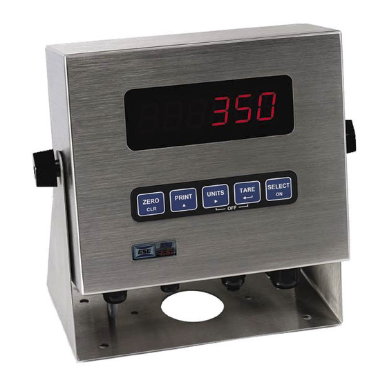
3 5 0 D I G I T A L E I G H T N D I C A T O R ISPLAY The M350 indicator is available with either a six digit, 7-segment green LED display, or a six digit, 7-segment black LCD display. The M350 displays alpha-numeric data, but due to the nature of 7-segment LEDs/LCD and the limitation of six digits, some information is abbreviated. -
Page 13: Annunciators
1 : I H A P T E R N T R O D U C T I O N NNUNCIATORS Annunciators provide mode and status information. When illuminated, they indicate the following conditions: Setpoint #1 activated (relay 1 closed). Setpoint #2 activated (relay 2 closed). -
Page 14: Standard Functions
3 5 0 D I G I T A L E I G H T N D I C A T O R TANDARD UNCTIONS The M350 includes built-in functions that you can enable through the Indicator Setup. Refer to Chapter 3: Configuration for information on the setup and operation of the following standard functions: •... - Page 15 1 : I H A P T E R N T R O D U C T I O N Table 1-1: Keyboard Functions Key Press Weigh Mode Count Mode Setup Mode Performs a gross zero Exits the Setup Mode function and/or clears Performs a quantity an entry in progress.
-
Page 16: Specifications
1.25A w/options installed (internal power supply version) Excitation Voltage 10 VDC Excitation Current 180 mA max. / (6) 350Ω bridge F.S. Signal Input 0.1 mV/V min – 20 mV/V max Signal Connection 4 lead or 6 lead with sense... - Page 17 1 : I H A P T E R N T R O D U C T I O N COMMUNICATIONS Serial RS232 bi-directional serial port Data Output 12 selectable fixed-format transmissions or 1 custom format (programmable via RS232) Protocol Selectable Baud Rate 150 –...
-
Page 19: Chapter 2: Installation
For information on installing options, see Chapter 6: Options. For NTEP and OIML details, see Chapter 5: Legal-for-Trade. IMPORTANT! The 350 Series indicators do not include an on/off switch and therefore must be installed near a power outlet socket that is easily accessible and in keeping with UL/CSA Safety Standards. -
Page 20: Desktop Mounting
3 5 0 D I G I T A L E I G H T N D I C A T O R ESKTOP OUNTING The standard enclosure is designed for desktop mounting. When set on a flat surface, the front face is angled for easy viewing. All wiring enters from the rear and can be secured with the included screw mounted cable ties. -
Page 21: Wiring
2 : I H A P T E R N S T A L L A T I O N Figure 2-4: M350 Zinc Die Cast Front Dimensions IRING A description of all wiring terminals is included on the bottom label of the zinc die cast enclosure as shown in Figure 2-5. -
Page 22: M350 Stainless Steel Dimensions
3 5 0 D I G I T A L E I G H T N D I C A T O R Figure 2-7: M350 Stainless Steel Dimensions... -
Page 23: Load Cell Connections
2 : I H A P T E R N S T A L L A T I O N ONNECTIONS A high quality braided shield cable with 16 to 24 AWG stranded wire is recommended for load cell or summing box connections. Secure the cable by the cable tie on the die cast model, or rout it through the strain relief supplied on the back of the internal power supply models (see Figure 2-8). -
Page 24: Serial Port Connections
Digital Ground Request-to-Send Clear-to-Send Do Not Connect Figure 2-9: GSE Serial Cable, Part Number 22-30-29752 A communication cable (P/N: 22-30-29752) may be purchased from GSE for connection to a serial device having a DB25 or DB9 connector (see Figure 2-9). -
Page 25: Remote Key Connection
2 : I H A P T E R N S T A L L A T I O N EMOTE ONNECTION A remote key may be connected to the M350 communication port to provide remote activation of print, tare, or zero functions. The connection for the remote key input is between pin 1 and pin 6 of the DB9 communication port connector (see Figure 2-10 for die cast, Figure 2-11 for stainless). - Page 26 Wire the plug as shown in Figure 2-12. Recommended plugs are AMP MTA .156” or MOLEX .156”. External DC power supply cable GSE P/N 22-30-35459 plugs into the 350 die cast unit rear connector with bare wires on the other end.
-
Page 27: M350 Internal Power Supply Model Ac Connections (J10)
Recommended connectors are GSE PN: 26-20-3365 (24 AWG) or GSE PN: 26-20-3366 (22 AWG) / Figure 2-14: M350 Internal AMP PN: 640441-3 (24 AWG) or AMP PN: Power Supply Model DC 640440-3 (22 AWG). -
Page 29: Chapter 3: M350 Configuration
3: M350 C HAPTER ONFIGURATION For the indicator to operate properly, you must configure a group of specific, individually numbered parameters. There are three types of parameters: Selection Parameters, Toggle Parameters and Key-In Parameters. Assigning a value to a parameter tells the indicator how to respond to a specific situation. - Page 30 3 5 0 D I G I T A L E I G H T N D I C A T O R To access Setup in a view-only mode: 1. From the Weigh Mode, press [ZERO] + [SELECT]. Setup ~ Enter Code 2.
- Page 31 3 : C H A P T E R O N F I G U R A T I O N To access a specific parameter (for example P200): 1. Press [ p ] four times to select the first digit. 2.
-
Page 32: Selection Parameters
3 5 0 D I G I T A L E I G H T N D I C A T O R To exit the Setup Mode without saving changes: 1. Press [ZERO] to begin exiting Setup Mode. Enter ~ =CAL! 2. -
Page 33: Key -I N Parameters
3 : C H A P T E R O N F I G U R A T I O N ARAMETERS Key-In Parameters are not limited to a list of choices, although there may be upper and lower value limits. A Key-In Parameter requires that a numeric value be entered using the front panel keys. - Page 34 3 5 0 D I G I T A L E I G H T N D I C A T O R ARAMETER Table 3-1: Parameter Map Parameter Display Default Valid Range/ Parameter Page Number Name Value Choices Description F.S.= 100.00 .01 –...
- Page 35 3 : C H A P T E R O N F I G U R A T I O N Parameter Display Default Valid Range/ Parameter Page Number Name Value Choices Description Send Press Off – Cycle Comm P210.01 (4 Selections) Transmit Stabl...
-
Page 36: Parameter Map
3 5 0 D I G I T A L E I G H T N D I C A T O R ARAMETER ETAILS P110 Full Scale Value (Key in) Denotes the full scale capacity. This value should not exceed the rated capacity of the weighing device. - Page 37 3 : C H A P T E R O N F I G U R A T I O N Filtering is used to filter out weight fluctuations caused by outside sources, such as vibrations or air currents. P117 Rate (Selection) Specifies how often the display is updated with new data.
- Page 38 3 5 0 D I G I T A L E I G H T N D I C A T O R When enabled, pressing [TARE] will wait for a no-motion condition and then bring the scale to a net zero reading. Disabling will prevent keypad tare operations.
- Page 39 3 : C H A P T E R O N F I G U R A T I O N 1. From the Weigh Mode, press [SELECT] to view the current net weight. 1.05 2. Press [SELECT] to view the current quantity/count. 3.
- Page 40 (P210) and / or the Remote Key selection (P800). Choice 0 Custom Transmit: User-defined serial data string (see Custom Transmit Setup on page 43). Choice 1 GSE Standard Transmit: XXX.XX kg Gross<CR><LF> XXX.XX kg Tare <CR><LF> XXX.XX kg Net <CR><LF>...
- Page 41 3 : C H A P T E R O N F I G U R A T I O N Choice 5: <STX><Signed DATA><sp><lb/kg><STAT><CR> Choice 6: <STX><Signed DATA><sp><lb/kg><CR> Choice 7: <STX><Unsigned DATA><sp><CR> Choice 8: <STX><Signed DATA><sp><lb/kg><sp><Gros/Net/Qty><STAT><SPS><CR> Choice 9: <STX><Signed DATA><sp><lb/kg><STAT><SPS><CR> Choice 10: <STX><Signed Displayed Weight><sp><lb/kg><SPS><CR>...
- Page 42 3 5 0 D I G I T A L E I G H T N D I C A T O R See <SPS> Setpoint Status below. <SPS> A single control code, decimal value of 13. <CR> A single control code, decimal value of 10. <LF>...
- Page 43 NOTE: The display will turn back on if data is received via the RS-232 Port. P423 Back Light (on/off) Toggle the back light on a 350 LCD P426 Low Battery Indication (Toggle) Press [ENTER] to enable or disable this option. Low battery will be indicated continuously if this feature is enabled without the battery option installed.
- Page 44 3 5 0 D I G I T A L E I G H T N D I C A T O R become the PM indicator. Note: The time must be entered as military time. If the mode is set for 12 hour, the time will be converted to a 12 hour clock.
- Page 45 3 : C H A P T E R O N F I G U R A T I O N Enables or disables the bargraph display on the LCD version of the M350 display. This setup parameter only appears if an LCD display is installed. See Bargraph (General) on page 58.
-
Page 46: Analog Output Setup
8,000 lbs. Reset state – Specifies analog 10 V (Max Output) P176.01 AnRst signal level when 350 enters 0 V (Min Output) Setup Mode. No Change* 0 –10 volts*, Specifies output type: voltage or P177.00... -
Page 47: Analog Output Calibration
3 : C H A P T E R O N F I G U R A T I O N NALOG UTPUT ALIBRATION This section requires firmware rev 010 or later. Table 3-4: Analog Output Calibration Parameters ARAMETER ISPLAYED ESCRIPTION CHOICES (*=D... - Page 48 N D I C A T O R NTERING NALOG ALIBRATION ALUES An example of the printout included with each analog option kit follows below: 100%s23640%i%e Access Setup Modes, Allowing Changes 60100%s%e P60100. c1998-GSE- 60101%s%e P60101. 0350p01009 60102%s%e P60102. 06-30-2000 60200%s%e P60200. BrdSn573192 60201%s%e P60201.
-
Page 49: Analog Output Example
3 : C H A P T E R O N F I G U R A T I O N NALOG UTPUT XAMPLE Analog Parameter Example Parameter Comments Description Value Setting P172.01 Net Weight 3.00 lb Current net weight. Analog Full Net weight value that would give P173.--... -
Page 50: Elements Of A Custom Transmit
Wordpad, etc.) , but you must save the custom transmit as a text (.txt) file. Instructions can also be sent keystroke by keystroke from a communications program. To do so, ignore the 350 display and enter the characters in the correct order. Figure 3-1 shows a custom transmit written in Wordpad. -
Page 51: Entering Ascii Text
3 : C H A P T E R O N F I G U R A T I O N Access Setup and Clear Old Custom Transmit ASCII Text ASCII Control Codes Gross, Tare and Net Parameters Exit Setup and Save Changes Figure 3-1: Custom Transmit File ASCII T NTERING... - Page 52 3 5 0 D I G I T A L E I G H T N D I C A T O R Table 3-5: ASCII / HEXADECIMAL CONVERSION CHART CHAR “ < > & ‘ ‘...
-
Page 53: Parameter Selection Numbers
3 : C H A P T E R O N F I G U R A T I O N ARAMETER ELECTION UMBERS The following sequence enters parameters into a custom transmit: %e , the parameter number, %e%e , a format code, and then %e%e with no intervening spaces. -
Page 54: Exiting Setup Mode And Saving Changes
3 5 0 D I G I T A L E I G H T N D I C A T O R Table 3-7: Custom Transmit Format Codes Choice Sample Print Result Description Fixed width (8 characters), right justified, “... -
Page 55: Time /Date Operation
3 : C H A P T E R O N F I G U R A T I O N PERATION The time and date feature is stored as volatile (time/date setting will be lost when the unit power is reset). The time/date parameter is available in the first two fixed transmits ( See Transmit Selection on page 34) and can be included in a custom transmit (See Custom Transmit Setup on page 43). - Page 56 3 5 0 D I G I T A L E I G H T N D I C A T O R To enter the time from the Enter~tine~00.00.00 prompt 1. Press [PRINT] to toggle through the numbers to enter the hour. Hours must be entered as military time.
-
Page 57: Remote Key Operation
3 : C H A P T E R O N F I G U R A T I O N EMOTE PERATION The M350 has four selectable remote key operations to choose from: Print, Tare, Zero and Setpoint. Only one of these operations may be assigned to the remote key input. -
Page 58: Display Capture Utility
3 5 0 D I G I T A L E I G H T N D I C A T O R Command ASCII Description Allows a piece weight to be entered Piece Wt. serially. For example, 0.10%9 will enter Entry a piece weight of 0.10. -
Page 59: General
3 : C H A P T E R O N F I G U R A T I O N ENERAL ETPOINT ETUP The M350 has several pre-programmed scale setpoint applications available at P5100. Various related setpoint parameters may appear according to which of the standard programs is chosen. -
Page 60: Activation Methods (General)
3 5 0 D I G I T A L E I G H T N D I C A T O R CTIVATION ETHODS ENERAL Setpoint activation for Fill, Batch, Discharge, and Both can be initiated in one of three ways: Tare, Remote or Auto. Check-weigh operations have no start function. -
Page 61: Learn Feature (General)
3 : C H A P T E R O N F I G U R A T I O N repeated tests, a system consistently over-fills by .5 lbs. This is the value that should be entered as the pre-act. The M350 would then deactivate the setpoint .5 lbs. -
Page 62: Changing Targets From The Weigh Mode (General)
3 5 0 D I G I T A L E I G H T N D I C A T O R HANGING ARGETS FROM THE EIGH ENERAL When a setpoint operation is configured from the Setup Mode, certain parameters are made available in the Weigh Mode. -
Page 63: Bargraph (General)
3 : C H A P T E R O N F I G U R A T I O N PA 2 ~ .5 7. Press [SELECT] to display the current Gross Weight. 15.12 ARGRAPH ENERAL A bargraph display is available for the ChecP, Fill, Batch, Dschg, Both and ChecA setpoint modes of operation. - Page 64 3 5 0 D I G I T A L E I G H T N D I C A T O R Figure 3-2: Example #1 Bargraph Segments (Weighted Value) Example#2: : “ChecP” (refer to Figure 3-3) Lower Limit is set at 50lbs. P5012 is set for 20% (Bar weight = 50 –...
- Page 65 3 : C H A P T E R O N F I G U R A T I O N Figure 3-4: Examples of the Bargraph "Below, Within and Above Tolerance" NOTE: (bargraph for filling and emptying modes) For modes other than check-weighing, the bars will be on only while the setpoints are on and during the "Done"...
-
Page 66: Percentage Check -Weighing
3 5 0 D I G I T A L E I G H T N D I C A T O R ERCENTAGE HECK EIGHING This feature is commonly used in check-weigh applications. After a target weight is entered, upper and lower tolerances are entered as a percentage of the target. -
Page 67: Fill
3 : C H A P T E R O N F I G U R A T I O N HANGING ARGETS FROM THE EIGH ERCENTAGE HECK EIGHING When Check-Weigh by Percentage is configured in the setpoint setup, the Targ 1 value automatically becomes an available mode for the [SELECT] key. -
Page 68: Activation Method (Fill)
3 5 0 D I G I T A L E I G H T N D I C A T O R Setpoint Selection Function Description Pre-Act 1 Available as Subset in P5114.1 PrAc 1 Weigh Mode Pre-Act 2 Available as Subset in P5115.1 PrAc 2 Weigh Mode... -
Page 69: Learn Feature (Fill)
3 : C H A P T E R O N F I G U R A T I O N EARN EATURE Pre-act 2 has a learn feature available which allows the indicator to adjust the final cutoff based on changing environmental conditions. See Learn Feature (General) on page 55 for ‘learn’... -
Page 70: Setpoint Setup (Batch)
3 5 0 D I G I T A L E I G H T N D I C A T O R Table 3-14: Setpoint Setup (Batch) Setpoint Selection Function Description P5100.3 Batch 2 or 3 ingredient batching. P5101.-- Targ1 Ingredient 1 target value. -
Page 71: Changing Targets From The Weigh Mode (Fill)
3 : C H A P T E R O N F I G U R A T I O N ACTS ATCH Pre-acts 1, 2 and 3 specify the final cutoff for each respective ingredient. See Per-acts (General) on page 54 for pre-act details. EARN EATURE ATCH... - Page 72 3 5 0 D I G I T A L E I G H T N D I C A T O R Parameter Setting Actual Cutoff Value Comments Target 1 = 30,000 Desired water weight. Targets are compared to net Based = Net weight.
-
Page 73: Discharge
3 : C H A P T E R O N F I G U R A T I O N ISCHARGE The discharge program is designed for single-speed or dual-speed dispensing of product from a larger weigh vessel. Discharge is a loss-in- weight application similar in operation to the fill program. -
Page 74: Pre-Acts (Discharge)
3 5 0 D I G I T A L E I G H T N D I C A T O R ACTS ISCHARGE Pre-act 1 is used for dual-speed dispensing. Pre-act 1 specifies when the system should switch from fast-discharge to slow-discharge. When using a single-speed device, pre-act 1 should be set to 0 from the Setup Mode. - Page 75 3 : C H A P T E R O N F I G U R A T I O N XAMPLE ISCHARGE With a system set up to dispense ball bearings from a 50,000 lb weigh-bin and the fast-feed requiring an early cutoff to slow-feed, the following settings might be used to achieve accurate dispensing of 1000 bearings: Parameter Setting Actual Cutoff Value...
-
Page 76: Setpoint Setup (Both)
3 5 0 D I G I T A L E I G H T N D I C A T O R Table 3-16: Setpoint Setup (Both) Setpoint Selection Function Description P5100.5 Both Select both setpoint operation. P5101.-- Targ1 Vessel fill target value. -
Page 77: Example (Both)
3 : C H A P T E R O N F I G U R A T I O N EARN EATURE Both pre-act 1 and 2 have the learn feature available which allows the indicator to automatically adjust the final cutoff based on changing environmental conditions. -
Page 78: Absolute Check -Weighing
3 5 0 D I G I T A L E I G H T N D I C A T O R Actual Cutoff Parameter Setting Comments Value Desired discharge target Targ 2 = 45 0 – 45 = (-45) (decreasing weight from a net zero: enter as a positive value). -
Page 79: Example (Absolute Check-Weighing)
3 : C H A P T E R O N F I G U R A T I O N Check-Weigh Annunciator Annunciator Setpoint Status (Requires Status Status Color (LED) Setpoint Option Board) SP 1 Relay 1 Contacts Closed, OVER Illuminated Relay 2 and 3 Contacts Open. - Page 80 3 5 0 D I G I T A L E I G H T N D I C A T O R Auto, Non-latching or Absolute. See Key-In Parameters on page 23 for instructions on using front panel keys for data entry. Table 3-18: Setpoint Setup (Independent) Setpoint Function...
-
Page 81: Independent Setpoint Operation
3 : C H A P T E R O N F I G U R A T I O N above the target. When set to Activate Below, the selected mode must actually be below the target. A setpoint option board may be installed to allow the M350 to directly control lights, buzzers, valves or relays (see Setpoint Card Connections on page 108). -
Page 82: Example (Independent)
3 5 0 D I G I T A L E I G H T N D I C A T O R XAMPLE NDEPENDENT Setup a continuous-cycle static weighing system that fills a weigh hopper from a storage bin. The weigh hopper should stop the fill at a predetermined target, dump the product into a bag, and then restart the fill. -
Page 83: Multi
3 : C H A P T E R O N F I G U R A T I O N RS-485 M ULTI ETWORK ETUP AND PERATION Table 3-19: RS-485 Network Parameters ARAMETER ISPLAYED CHOICES ESCRIPTION (*=D ETTING EFAULT Enable or disable RS-485 P250.00 rS485... -
Page 84: Network Protocol
3 5 0 D I G I T A L E I G H T N D I C A T O R of the transmission. The receive routine of the M350 then resets to look for the <STX> character again. The data packet format recognized by the M350 is defined as follows: <STX><ADDRESS><DATA><DATA><DATA><DATA>…<ETX>... -
Page 85: Chapter 4: Calibration Mode
4: C HAPTER ALIBRATION Calibration uses the load cell(s) output signal to establish zero (no load) and span (test load) reference points. Calibration information is retained in non-volatile memory in the event of power-loss. There are two methods of accessing the Calibration Mode, exiting the Setup Mode, and entering Fast Calibration. -
Page 86: Performing Calibration
3 5 0 D I G I T A L E I G H T N D I C A T O R ERFORMING ALIBRATION Calibration always begins by establishing a zero (no-load) reference. A complete calibration also requires establishing a span (test load) reference. This section details various methods for obtaining zero and span references. - Page 87 4 : C H A P T E R A L I B R A T I O N 0.00 5. Pause for motion delay. Enter ~ Load ~ 0.00 6. Place a 100lb test weight on scale. Enter ~ Load ~ 99.66 7.
- Page 88 3 5 0 D I G I T A L E I G H T N D I C A T O R 3. Apply a 10000 lb test weight to verify calibration. 9970. 4. Press [ZERO] + [SELECT]. Setup 5.
- Page 89 4 : C H A P T E R A L I B R A T I O N reference. Test weights may then be added to verify calibration. The zero reference determined during the last calibration is not affected. False Zero Calibration Without Removing Existing Load Example: 1.
- Page 90 3 5 0 D I G I T A L E I G H T N D I C A T O R Only Zero is used to establish a new calibration zero without affecting the span. This is useful for correcting changes to the scale’s dead load, for example adding safety rails to a truck scale platform.
- Page 91 4 : C H A P T E R A L I B R A T I O N If Code 02 (under-load) or Code 03 (over-load) is displayed during calibration, press [CLR] to perform a calibration reset. Reset Calibration Gain Factors Example: 1.
-
Page 92: Establishing Span
3 5 0 D I G I T A L E I G H T N D I C A T O R 15. Press [ 8 ] to save calibration. Enter ~ =End 16. Press [ 8 ] to exit calibration. 100.00 17. -
Page 93: Exiting Calibration
4 : C H A P T E R A L I B R A T I O N XITING ALIBRATION Once zero and span have been established, the newly acquired calibration information must be saved to non-volatile memory before it will be realized in the Weigh Mode. -
Page 95: Ntep Requirements
5: L HAPTER EGAL RADE The M350 default parameter setup does not ensure compliance with legal- for-trade installations as mandated by local weights and measures authorities. This chapter contains information on NTEP and OIML regulations, sealing and audit trails, and other requirements. Since legal-for-trade requirements may vary, you must ensure that the M350 is installed in accordance with all local regulations. -
Page 96: Ntep Panel Mount Requirements
MUST match. The tag is designed to be applied to the top right edge of the enclosure or to the lower right of the front of the unit. Drill pins (GSE part number 38-04-2960) are supplied with the panel mount kit to mount the tag. -
Page 97: Oiml Requirements
5 : L H A P T E R E G A L F O R R A D E OIML R EQUIREMENTS The International Organization of Legal Metrology is an inter- governmental body which harmonizes the national metrology regulations of its world wide members. -
Page 98: Physical Seal
3 5 0 D I G I T A L E I G H T N D I C A T O R HYSICAL The most common sealing method is a lead-wire seal. The M350 provides an easy means of applying this type of seal as shown in Figure 5-3. Before applying a wire seal, move the program jumper to the ‘NO’... -
Page 99: Audit Trails
5 : L H A P T E R E G A L F O R R A D E Figure 5-3: Physical Seals (Zinc Die-Cast / Stainless Steel) UDIT RAILS Three separate incrementing, non-resetable audit trail parameters are used by the M350 to indicate changes to various parameters, P60201 –... - Page 100 3 5 0 D I G I T A L E I G H T N D I C A T O R To view audit trail parameters: 1. Press [ZERO] + [SELECT]. Setup Enter ~ Code! 2. Press [ 8 ]. -No- ~ Chgs! P112 ~ FS ~ xx.xx 3.
-
Page 101: Chapter 6: M350 Option Kits
ERIPHERAL PTIONS The following options are available for the M350: • Swivel Bracket Kit (die cast model) (GSE P/N 24350B-301C0) Allows the indicator to be securely mounted to any surface. • Panel Mount Kit (die cast model) (GSE P/N 24350B-300C0) Allows the indicator to be easily mounted into existing cabinetry. -
Page 102: Swivel Bracket
3 5 0 D I G I T A L E I G H T N D I C A T O R WIVEL RACKET The M350 has an optional stainless steel swivel bracket for secure mounting to desks, tabletops or walls. See the Mounting section beginning on page 9 for instructions on mounting the M350 using the swivel bracket. -
Page 103: Panel Mount Kit
6 : O H A P T E R P T I O N S ANEL OUNT The Panel Mount Kit provides an easy way to mount the indicator into new or existing cabinetry. See Figure 6-2 for detailed instructions on panel mounting the M350. -
Page 104: Analog Card Connections
See Analog Output Setup on page 40 for analog output software configuration details. The Model 350 contains components which could be damaged by Electrostatic Discharge (ESD) if serviced improperly. Use proper ESD precautions (wear a wrist strap connected to ground, use grounded work stations, etc.) when opening the enclosure. -
Page 105: Option Board Installation (Die Cast M350)
6 : O H A P T E R P T I O N S To install the Analog Output Module (350 die cast model): 1. Open the indicator. Remove the four screws from the back of the unit. It may help to remove the swivel bracket, if installed. - Page 106 I G I T A L E I G H T N D I C A T O R To install the Analog Output Model (350 Stainless Model): 1. Open the indicator. Remove the eight screws from the back of the unit.
-
Page 107: Analog Output Connections
6 : O H A P T E R P T I O N S 7. Secure the bracket into position with the hex nuts supplied with the kit. Do not over tighten. 8. Place one set (four pieces) of the nylon sleeve type stand-offs onto the four studs of the option bracket. - Page 108 3 5 0 D I G I T A L E I G H T N D I C A T O R Place this label on the rear of the indicator (die cast), above the analog option knockout. (Stainless steel model) Cut off the text “ANALOG OUTPUTS” from the label and place it on the connector shown below (apply to the area just under the field external wire terminals).
-
Page 109: Analog Board Diagnostic And Test Procedures
6 : O H A P T E R P T I O N S NALOG OARD IAGNOSTIC AND ROCEDURES The following test procedures affect the analog output signal levels. Be sure to disconnect all peripheral devices attached to the analog option card. Test equipment needed: precision DC voltmeter, 500 ohm precision resistor. - Page 110 3 5 0 D I G I T A L E I G H T N D I C A T O R Voltmeter readings are based on the use of a 500 ohm precision resistor. Caution! Do not exceed 500 ohms. 1.
- Page 111 6 : O H A P T E R P T I O N S To test the 4-20mA output mode: Voltmeter readings are based on the use of a 500 ohm precision resistor. Caution! Do not exceed 500 ohms. 1.
-
Page 112: Analog Output Setup
10,000 lb. output set to 8 will stop increasing its analog signal at 8,000 lbs. Reset state – Specifies analog 10 V (Max Output) signal level when MODEL 350 0 V (Min Output) P176.01 AnRst and MODEL 350 enters Setup No Change* Mode. -
Page 113: Analog Output Calibration
6 : O H A P T E R P T I O N S NALOG UTPUT ALIBRATION Table 6-3: Analog Output Calibration Parameters ARAMETER ISPLAYED ESCRIPTION CHOICES (*=D ETTING EFAULT Value required to precisely Numeric Entry: P61200 10oFF output 0V in 0 – 10V 0 to 15,000 output mode (i.e. - Page 114 Exit Setup Mode Analog calibration values can be entered into the MODEL 350 AND MODEL 350 by keying in the data in the left-hand column, beginning at the line starting with “61200…”, replacing the “%s” character pairs with the [SELECT] key and “%e” with the [ENTER] key. The line with the “%c”...
-
Page 115: Analog Output Example
6 : O H A P T E R P T I O N S NALOG UTPUT XAMPLE Analog Parameter Example Parameter Comments Description Value Setting P172.01 Net Weight 3.00 lb Current net weight. Analog Full Net weight value that would give P173.-- Scale maximum analog output. -
Page 116: Setpoint Card Connections
See General Setpoint Setup on page 53 for setpoint software configuration details. The Model 350 contains components which could be damaged by Electrostatic Discharge (ESD) if serviced improperly. Use proper ESD precautions (wear a wrist strap connected to ground, use grounded work stations, etc.) when opening the enclosure. - Page 117 1. Open the indicator. Remove the eight screws from the back of the unit. 2. Locate the three studs and one thru-hole on the 350 main board that the option mounting bracket will be attached to. See Figure 6-6. Remove the nuts from the three studs on the main board.
- Page 118 3 5 0 D I G I T A L E I G H T N D I C A T O R 3. Install the nylon stand-off supplied with the option bracket kit into the thru-hole on the option bracket. See Figure 6-6.
-
Page 119: Setpoint Output Specifications ( 24350B-100C0)
6 : O H A P T E R P T I O N S (J7) on the main board before installing the card. Also be sure the cable is attached to the right-most connector (J3) (as viewed from the component side of the option board). -
Page 120: Setpoint Output Specifications ( 24350B-100C1)
3 5 0 D I G I T A L E I G H T N D I C A T O R Place this label above the setpoint card knockout (die cast). (Stainless steel model) Cut off the text “SETPOINT OUTPUTS” from the label and Figure 6-7 place it on the connector shown in (apply to the area just under the... -
Page 121: Setpoint Output Specifications ( 24350B-100C2)
6 : O H A P T E R P T I O N S Place this label above the setpoint card knockout (die cast). (Stainless steel model) Cut off the text “SETPOINT OUTPUTS” from the label and Figure 6-7 place it on the connector shown in (apply to the area just under the field external wire terminals). -
Page 122: Wire The Option Connector In Accordance With The Label (Left To Right)
3 5 0 D I G I T A L E I G H T N D I C A T O R Place this label above the setpoint card knockout (die cast) (Stainless steel model) Cut off the text “SETPOINT OUTPUTS” from the label and Figure 6-7 place it on the connector shown in (apply to the area just under the... -
Page 123: Setpoint Board Diagnostic And Test Procedures
6 : O H A P T E R P T I O N S ETPOINT OARD IAGNOSTIC AND ROCEDURES This test procedure affects the setpoint output. Be sure to disconnect all peripheral devices attached to the setpoint option card. Test Equipment needed: Load device with power source. -
Page 124: Networking
Firmware revision 450350-01013 or later is required for RS-485 operation. For setup and operation information, see page 79. The Model 350 contains components which could be damaged by Electrostatic Discharge (ESD) if serviced improperly. Use proper ESD precautions (wear a wrist strap connected to ground, use grounded work stations, etc.) when opening the enclosure. - Page 125 P T I O N S least 8 in/lb torque. 7. Place the included sticker over the rear connector sticker RS232. To install the RS-485 Network Options (350 Stainless Model): 1. Open the indicator. Remove the eight screws from the back of the unit and remove the cover.
-
Page 126: Network Connections
3 5 0 D I G I T A L E I G H T N D I C A T O R ETWORK ONNECTIONS Apply the supplied label over the appropriate COMM PORT pin designations. On the stainless steel enclosure, apply the label marked M350 SS to the main board (J6). - Page 127 6 : O H A P T E R P T I O N S UPLEX WIRE Removing jumpers 1, 2 and 4 on the RS-485 option board requires that the transmit and receive lines be wired independently of one another. The RX B(+) and RX A(-) receive lines must be wired in parallel to the next device’s RX B(+) and RX A(-) receive lines , and the TX B(+) and TX A(- ) transmit lines must be wired in parallel to the next device’s TX B(+) and...
- Page 128 3 5 0 D I G I T A L E I G H T N D I C A T O R Figure 6-10: Half Duplex Wiring Schematic...
- Page 129 6 : O H A P T E R P T I O N S Figure 6-11: Full Duplex Wiring Schematic...
-
Page 130: A Current Loop Option
3 5 0 D I G I T A L E I G H T N D I C A T O R URRENT PTION Description: This option will convert the comm port of the indicator to an 20 mA current loop instead of an RS-232. This is a digital communication signal and should not be confused with a 4 to 20-mA (or 0-20 mA) which are analog output signals. -
Page 131: Active/Passive
6 : O H A P T E R P T I O N S CTIVE ASSIVE The Tx output may be used as an active or passive output from the indicator. Either active or passive is chosen depending upon which terminals are used for the connections. -
Page 132: Connected Devices
Table 10: Label Terminology TRANSMITTER CONNECTIONS Indicator Transmitter Transmit current Transmit current input, Output input, Active Passive 350 SS & TX OUT TX ACTIV TX PASS RECEIVER CONNECTIONS Indicator Receiver current output Receiver current input 350 SS & RX PASS... -
Page 133: Battery Power Supply
OUNTING The circuit board and battery fit inside the die cast and stainless steel 350 enclosures. The circuit board acts as the hold down for the battery in both enclosures. Please refer to Figure 6-12 for installation instructions for the M350 Stainless Steel Enclosure, or Figure 6-13 for installation instructions for the M350 Die Cast Enclosure. -
Page 134: Battery Option Installation (Stainless Steel Enclosure)
3 5 0 D I G I T A L E I G H T N D I C A T O R Figure 6-12: Battery Option Installation (Stainless Steel Enclosure) -
Page 135: Battery Option Installation (Die Cast Enclosure)
6 : O H A P T E R P T I O N S Figure 6-13: Battery Option Installation (Die Cast Enclosure) -
Page 136: Pin Designations
E I G H T N D I C A T O R ESIGNATIONS See Figure 6-14 for 350 main board battery connections (marked J9 for the stainless enclosure, and J3 for the die cast enclosure). DESCRIPTION Positive terminal (VDC signal input) -
Page 137: Battery Charging
If you are retrofitting an older M350 Stainless Steel Indicator, please contact your sales representative to get one each of the following GSE part numbers: • 36-20-2450 Rubber washer, 0.49 ID x 1.06 OD x 0.093 thick •... -
Page 138: Low Battery Indication
3 5 0 D I G I T A L E I G H T N D I C A T O R ATTERY NDICATION The Low Battery indication occurs when the battery is discharged below 11.4 VDC. Parameter 426 enables or disables the low battery indication. Low battery will be indicated continuously if this feature is enabled without the battery option installed. -
Page 139: Splash Guard Protection
Be sure to use a pressure relief valve (PN# 44-30-5531). - IEC NTERNATIONAL RANSFORMER The Model 350 zinc die cast transformer (GSE P/N 20-20-35190) allows the 350 to run on overseas current. Mounting tabs and line cords provide installation flexibility, allowing easy mounting to walls, tables, shelves, etc. -
Page 140: Specifications
Cord length from the transformer to the IEC (male) plug end is another six feet ( two meters). RANSFORMERS VAILABLE • Model 350 Zinc Die Cast Transformer (GSE part # 20-20-35190) LINE CORDS VAILABLE • GSE part # 22-30-1022 – for use in Australia, Argentina, New Zealand, and China •... - Page 141 6 : O H A P T E R P T I O N S...
-
Page 143: Error Messages
7: T HAPTER ROUBLESHOOTING This chapter contains error messages and information parameters, as well as information on setup parameter selections and A/D Calibration. RROR ESSAGES The M350 utilizes the following types of error messages: Operational Errors, Setup Mode Errors, Hardware Errors, Calibration Errors, Communication Errors, and Miscellaneous Errors. -
Page 144: Setup Mode Errors
3 5 0 D I G I T A L E I G H T N D I C A T O R Print ~ Abort Acknowledges that a motion delayed print request was aborted. Add ~ Load! If displayed after performing a count sample, this message indicates that a larger sample size is required. -
Page 145: Hardware Errors
7 : T H A P T E R R O U B L E S H O O T I N G ResGT ~ 25E3 The number of divisions exceeds 25000 (see P110, P111). ResLT ~ 100! The number of divisions is less than 100 (see P110, P111). -
Page 146: Calibration Errors
3 5 0 D I G I T A L E I G H T N D I C A T O R Ch.XXXX A checksum error occurred during power-up. All anunciators are lit. The EPROM integrity test failed or is improperly seated. E2 ~ Full! The EEPROM setup exceeds the memory capacity. -
Page 147: Miscellaneous Errors
7 : T H A P T E R R O U B L E S H O O T I N G TrHold Data transmission is inhibited due to a deasserted handshake. Press [CLR] to abort transmission. Check P204. ISCELLANEOUS RRORS T.X.YYYY... -
Page 148: Information Mode Parameters
NAME DESCRIPTION 60000 E2Ins Total amount of EEPROM storage. 60001 E2Fre Amount of available EEPROM storage. 60100 -GSE- ~ c1998 Copyright statement. 60101 0350P ~ 01001 Firmware revision code. 60102 02- 10 ~ 1998 Firmware date code. 60200 b sn ~ 10001 Main circuit board serial number. - Page 149 7 : T H A P T E R R O U B L E S H O O T I N G PARAMETER NAME DESCRIPTION Amount of weight (in default units) zeroed Zrtrc ~ Load 61103 by the zero track feature since [ZERO] was 0.00000 last pressed.
-
Page 150: A/D Calibration Procedure
A/D. However, if the values stored at parameters P61110 – P61121 appear to be reset to 0.00000 and/or 1.00000, then A/D recalibration is necessary. Contact GSE Scale Systems or your local authorized GSE distributor for more information on this procedure... - Page 151 Your GSE Distributor is: PART NUMBER: 39-10-34792...
Need help?
Do you have a question about the 350 and is the answer not in the manual?
Questions and answers