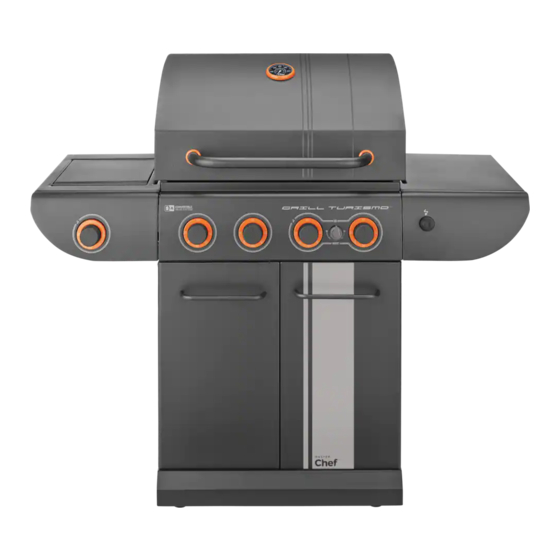
Master Chef GRILL TURISMO Assembly Manual
4-burner convertible barbecue
Hide thumbs
Also See for GRILL TURISMO:
- Assembly manual (28 pages) ,
- Manual (28 pages) ,
- Safety and care manual (24 pages)
Advertisement
Table of Contents
- 1 Hardware Pack
- 2 Tools Needed for Assembly
- 3 Parts List for 085-3137-6 / G45323
- 4 Exploded Diagram for 085-3137-6 / G45323
- 5 Assembly Instructions
- 6 Left Side Shelf Assembly
- 7 Right Side Shelf Assembly
- 8 Electronic Ignition Assembly
- 9 For Propane Model Only
- 10 How to Convert Your BBQ to Natural Gas
- 11 Warning Hot Surfaces
- 12 Customize Your Barbecue
- 13 Side Burner Control Panel
- 14 Main Control Panel
- Download this manual
GRILL TURISMO 4-BURNER
TM
CONvERTIBLE BARBECUE
Assembly Manual
085-3137-6 / G45323
1 YeAr liMited WArrAntY
reAd And sAve MAnuAl for future reference.
Assemble your grill immediately.
Missing or damaged parts claims must be submitted within 30 days of purchase date.
for product inquiries, parts, warranty and troubleshooting support,
please call 1-855-453-2150.
ANSI Z21.58-2015 / CSA 1.6-2015
ANSI Z21.58-2015 / CSA 1.6-2015
ANSI Z21.58-2015 / CSA 1.6-2015
Advertisement
Table of Contents

Related Manuals for Master Chef GRILL TURISMO


Summary of Contents for Master Chef GRILL TURISMO
- Page 1 GRILL TURISMO 4-BURNER CONvERTIBLE BARBECUE Assembly Manual 085-3137-6 / G45323 1 YeAr liMited WArrAntY reAd And sAve MAnuAl for future reference. Assemble your grill immediately. Missing or damaged parts claims must be submitted within 30 days of purchase date. for product inquiries, parts, warranty and troubleshooting support, please call 1-855-453-2150.
- Page 2 H e A v Y A r t i c l e n e e d s 2 t o l i f t THIS MANUAL MUST REMAIN WITH THE PRODUCT AT ALL TIMES To ORDER non-warranty replacement parts or accessories, or to register your warranty, please visit us on the web at www.masterchefbbqs.com cAution...
-
Page 3: Hardware Pack
HARDWARE PACK tools needed for AsseMBlY KeY # descriPtion PArt nuMBer QuAntitY 1/4” - 20 UNC x 38 Screw 20120-13038-250 1/4’’ - 20 UNC x 18 Screw 20120-13018-250 • #2 Star-head screwdriver (long and short) 1/4” - 20 UNC x 13 Screw 20120-13013-250 •... - Page 4 PARts List foR 085-3137-6 / G45323 KeY # QuAntitY descriPtion PArt no. Top Lid Assembly G453-8300-01 Lid Handle G453-0085-01 Lid Handle Bezel - Stainless G453-0086-01S Thermometer G364-0004-02 Thermometer Bezel - Stainless G453-0084-01S Screw for Top Lid G466-0007-03 Lid Bumper, Front G508-0063-01 Lid Bumper, Rear G303-0038-01...
- Page 5 EXPLoDED DiAGRAM foR 085-3137-6 / G45323 DE DF F5 - Custom Bezel Kit Quantity Description Part No. Lid Handle Bezel - Blue G453-0086-01B Lid Handle Bezel - Orange G453-0086-01O Thermometer Bezel - Blue G453-0084-01B SAFETy ASSEMBLy AND CARE G453-0084-01O Thermometer Bezel - Orange MANUAL MANUAL HARDWARE...
-
Page 6: Assembly Instructions
AssEMBLY iNstRUCtioNs Note: two people required for all assembly steps. Separate the 2 different types of castors: 2 Locking Castors (EE) and 2 Regular Castors (EF). Note: Regular Castors (Ef) need to be assembled to the front of the Bottom shelf (ED), and Locking Castors (EE) need to be Front assembled to the back of the Bottom shelf... - Page 7 AssEMBLY iNstRUCtioNs tHis stEP REQUiREs 3 PEoPLE. Do Not AttEMPt ALoNE. EXtREMELY HEAVY! Position the Top Lid Assembly and Burner Box Assembly (A & B) onto the Cart Assembly (C), as shown. Front View Attach the Upper Back Panel (BK) to both the Left And Right Side Panels (EB &...
- Page 8 AssEMBLY iNstRUCtioNs Assemble the Door Support Rail (EA) to the Left and Right Upper Side Panels (EB and EC), as shown. WARNiNG: this part may have sharp edges. Wear protective gloves when assembling. Front View yOU WILL NEED: Close Up...
- Page 9 AssEMBLY iNstRUCtioNs left side sHelf AsseMBlY tiP: Do not tighten until all hardware is in place. a. Mount the Left Side Burner Side Shelf (DA and DB) onto the two support brackets, located on the left, upper side panel of the Burner Box (BA).
- Page 10 AssEMBLY iNstRUCtioNs a. Remove the hardware that is pre-assembled to the Side Burner Valve (DE). Assemble the Side Burner Valve (DE) to the Left Side Shelf Fascia (DB), using the hardware removed, as shown in figure A. b. Assemble the Side Burner Control Knob (#13) to the Side Burner Valve (DE).
- Page 11 AssEMBLY iNstRUCtioNs b. Make sure that the Side Burner (DG) engages the Side Burner Valve (DE). Attach the Wing Nut (#10) to the Side Burner (DG), as shown in figure B. yOU WILL NEED: Left side view c. Attach the end of the Side Burner Electrode Wire (DH) to the underside of the Side Burner Electrode (DG), as shown.
- Page 12 AssEMBLY iNstRUCtioNs riGHt side sHelf AsseMBlY tiP: Do not tighten until all hardware is in place. a. Mount the Right Side Shelf (DJ and DK) onto the two support brackets, located on the right, upper side panel of the Burner Box (BA). b.
- Page 13 AssEMBLY iNstRUCtioNs electronic iGnition AsseMBlY Battery a. Remove the Ignition Battery Cover (CF2) and the plastic nut from the Electronic Ignition Assembly (CF1). b. Position the Electronic Ignition Assembly (CF1) Plastic Nut through the opening in the Right Side Shelf Fascia (DK) and secure using the plastic nut.
- Page 14 AssEMBLY iNstRUCtioNs Assemble the Heat Shield (CI) to the bottom of the Door Support Rail (EA) and the Upper back panel (BK), as shown in figure A and B. yOU WILL NEED: Front view Close up Back view Close up...
- Page 15 AssEMBLY iNstRUCtioNs a. Assemble the Left and Right Tracks (CK and CL) for the Grease Tray (CJ), as shown in figures A-C. yOU WILL NEED: Close up, back Close up, front b. Insert the Grease Tray (CJ) into the opening of the Upper Back Panel (BK).
- Page 16 AssEMBLY iNstRUCtioNs Assemble the Door Handle (EI) to the Left and Right Door Assembly (EG and EH). Left Door Handle yOU WILL NEED: Right Door Handle yOU WILL NEED:...
- Page 17 AssEMBLY iNstRUCtioNs a. Assemble the Right Door Assembly (EH), to the Bottom Shelf (ED) by inserting the fixed pin (bottom of door) into the hole provided (figure B). Close up, bottom of door b. Assemble the top of the Door Assembly (EH) to the Door Support Rail (EA), by pressing in the door support pin and aligning with the hole located on the top right corner of the door...
- Page 18 AssEMBLY iNstRUCtioNs Your Model includes the convertiBle Attention: Before completing steps 15 to 17, follow the vAlve sYsteM™. if you would like to steps outlined in the CONVERTIBLE VALVE convert your BBQ from ProPAne to SySTEM™ instruction manual that accompanied nAturAl GAs, the following kit is required the kit.
- Page 19 AssEMBLY iNstRUCtioNs Place the Cooking Grates (BI) into the Burner Box (BA). Insert the two small positioning rods of the Warming Rack (BJ) into the rear panel of the Burner Box (BA).
- Page 20 Bottom Shelf (ED), as shown in figure C. Attention foR YoUR sAfEtY, Do Not AttEMPt to LiGHt tHis BBQ UNtiL YoU HAVE REViEWED PAGEs 4-8 of tHE MAstER CHEf® sAfEtY & CARE MANUAL. ALL sAfEtY AND LEAK tEsts MUst BE PERfoRMED BY tHE END UsER, PRioR to LiGHtiNG tHis BBQ.
- Page 21 AssEMBLY iNstRUCtioNs HoW to convert Your BBQ to nAturAl GAs This barbecue was sold PROPANE READy, if you wish to run your barbecue on Natural Gas you must purchase the Natural Gas Conversion Kit sold at Canadian Tire, product number: 085-2261-4.
- Page 22 WArninG Hot surfAces cAution! • Avoid Burns! • do not toucH WHen BBQ is in use! • eXtreMelY Hot surfAce! * sHADED AREAs BECoME EXtREMELY Hot WHEN iN UsE.
- Page 23 CUstoMiZE YoUR BARBECUE Your barbecue comes with tWo ADDitioNAL sEts of BEZELs! follow these instructions if you would like to change your bezel color to gray or electric blue! Choose your color from the Custom Bezel Kit (F5). Remove Control Knobs (CC) from the Control Panel (CH) and Side Shelf Fascia (DB).
- Page 24 CUstoMiZE YoUR BARBECUE side Burner control PAnel iMPortAnt: cHAnGe 1 BeZel At A tiMe. Remove the bezel hardware (left and right screw) as shown. Put hardware aside. Unscrew, but DO NOT REMOVE the side burner valve hardware (top and bottom screw). Turn bezel clockwise slightly, to remove.
- Page 25 CUstoMiZE YoUR BARBECUE iMPortAnt: cHAnGe 1 BeZel MAin control PAnel At A tiMe. Unscrew, but DO NOT REMOVE the valve hardware (top and bottom screw). Turn bezel clockwise slightly, to remove. Position new bezel on valve hardware. Turn counter-clockwise. Tighten hardware. rePeAt stePs 4A to 4e to cHAnGe tHe reMAininG BeZels.
- Page 26 CUstoMiZE YoUR BARBECUE Assemble Control Knobs (CC), removed in Step 2, back to Control Panel (CH) and Side Shelf Fascia (DB).
- Page 27 CUstoMiZE YoUR BARBECUE Remove Thermometer (AD), Thermometer Bezel (AE), and hardware from Top Lid Assembly (AA). Put hardware aside. Assemble Thermometer (AD) and new Thermometer Bezel (AE) back to Top Lid Assembly (AA), using hardware removed in Step 6.
- Page 28 CUstoMiZE YoUR BARBECUE Remove Lid Handle (AB) and Lid Handle Bezels (AC) from Top Lid Assembly (AA). Put hardware aside. Attention BE CAREfUL Not to DRoP HARDWARE. Assemble Lid Handle (AB) and new Lid Handle Bezels (AC), back to Top Lid Assembly (AA), using hardware removed in Step 8.
- Page 29 Visit www.masterchefbbqs.com to complete product registration. Master Chef® Customer Service 1-855-453-2150 Trileaf Distributions Trifeuil Toronto, Ontario M4S 2B8...
Need help?
Do you have a question about the GRILL TURISMO and is the answer not in the manual?
Questions and answers