Table of Contents
Advertisement
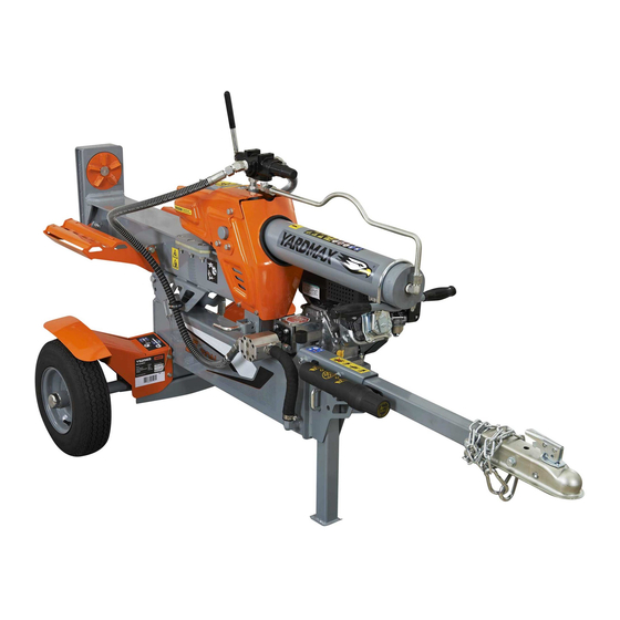
Gas Log Splitter
Operator's Manual
MODEL NUMBER
YS2565
YS2865
YS3065
YS3567
SERIAL NUMBER
PURCHASE DATE
Both model number and serial
number may be found on the
main label. You should record
both of them in a safe place for
future use.
READ AND UNDERSTAND THE ENTIRE MANUAL BEFORE OPERATING MACHINE
FOR YOUR SAFETY
Save This Manual for Future Reference
Tame the Great Outdoors
TM
Advertisement
Table of Contents

Related Manuals for YARDMAX YS2565


Summary of Contents for YARDMAX YS2565
- Page 1 Save This Manual for Future Reference Gas Log Splitter Operator’s Manual MODEL NUMBER YS2565 YS2865 YS3065 YS3567 SERIAL NUMBER PURCHASE DATE Both model number and serial number may be found on the main label. You should record both of them in a safe place for future use.
-
Page 2: Table Of Contents
Up for the job? YARDMAX is. When looking for outdoor power equipment (OPE) to get the job done right, at the right price, YARDMAX delivers the perfect combination of performance and practicality. YARDMAX has a solution that’s right for you. -
Page 3: Ys2565Pm01 - 1609
California to cause cancer and birth defects DISCLAIMER or other reproductive harm. YARDMAX reserves the right to discontinue, change, ENVIRONMENTAL and improve its products at any time without notice or obligation to the purchaser. The descriptions and... -
Page 4: Specifications
SUPPORT Have questions about your YARDMAX equipment? Call us at 844-YARDMAX, email us at support@yardmax.com, or contact us via your favorite social media site. SPECIFICATIONS Model # YS2565 YS2865 YS3065 YS3567 Splitting Force* 25 Ton 28 Ton 30 Ton 35 Ton log Capacity 25.5"... -
Page 5: Optional
Gas log Splitter Operator’s Manual » Model # YS2565 YS2865 YS3065 YS3567 Pump Size 14 GPM 14 GPM 17 GPM 17 GPM Hydraulic Cylinder bore 4" 4.5" 4.5" 5" Hydraulic Cylinder Stroke 23.5" 23.5" 23.5" 23.5" Hydraulic Rod Diameter 1.75"... -
Page 6: Symbols
SYMBOLS The rating plate on your machine may show symbols. These represent important information about the product or instructions on its use. Never remove partially split wood from Read these instructions carefully. the wedge with your hands. Fingers may become trapped between the split wood. Wear eye protection. -
Page 7: Safety
Gas log Splitter Operator’s Manual » SAFETY GENERAL SAFETY RULES Wear appropriate hearing protection. UNDERSTAND YOUR MACHINE Read this manual and labels affixed to the machine to understand Always keep hands and feet away from all moving parts during its limitations and potential hazards. operation. - Page 8 ENGINE SAFETY Avoid creating a source of ignition for spilled fuel. If fuel is spilled, do not attempt to start the engine but move the machine away This machine is equipped with an internal combustion engine. from the area of spillage and avoid creating any source of ignition Do not use on or near any unimproved, forest covered, or brush until fuel vapors have dissipated.
- Page 9 Gas log Splitter Operator’s Manual » SPECIFIC SAFETY RULES VERTICAL OPERATING POSITION PREPARATION OF THE LOG both ends of the log should be cut as square as possible to prevent the log from rotating out of the splitter during operation. Never split logs greater than the specified log capacity.
-
Page 10: Unpacking The Container
Check before towing to make sure the log splitter is correctly and Use extra care when towing the log splitter. Do not exceed 45 securely attached to the towing vehicle and the safety chains are mph. Towing the log splitter at a speed greater than 45 mph could secured to the hitch or bumper of the vehicle with enough slack result in loss of control, damage to the equipment, serious injury, to allow turning. -
Page 11: Contents Supplied
Gas log Splitter Operator’s Manual » Figure 1b COnTEnTS SUPPlIED Your YARDMAX log splitter comes partially assembled and contains the following: OPTIONAL Handware Kit 1. beam and Reservoir with Engine 3. Fender (Right) 2. Fender (left) 4. Wheel Axle Unpacking the Container & Contents Supplied... -
Page 12: Assembly
11. beam lock bracket 12. Muffler (YS2565 and YS2865 only) 13. Operator’s Manual and Engine Manual M10 X 25 14. Tools for Spark Plug Assembly (YS2565 and YS2865 only) 15. log Table (Optional) 16. Hardware Kit, Including: 6 X 40... -
Page 13: 1 | Introduction
Gas log Splitter Operator’s Manual » SPLIT CONTROL LEVER 1. Holding the hydraulic cylinder handle, pull out the cylinder slowly and in a straight line until the output shaft in the cylinder is against the trunnion mount and locked in the U-Shaped Bracket U-shaped groove. -
Page 14: Ys2565Pm01
LOG STRIPPER (YS2565, YS2865, and YS3065 ONLY) TOW BAR Insert the tow bar into the tank bracket and align the holes. 1. Align holes in the log stripper with the holes in the trunnion Connect and tighten the tow bar to the tank by using the M12x80 mount. -
Page 15: 1 | Introduction
Gas log Splitter Operator’s Manual » 3. Slide the anti-dust washer and one roller bearing onto the axle. 11. Remove the two M8x45 bolts, flat washers, and nuts. Use a soft-faced hammer to tap the roller bearing lightly to make sure the bearing is in the right position. 4. -
Page 16: 1 | Introduction
14. Move the bridge pin and lock pin from the upper hole to the 16. Rotate the bottom pallet slowly until there is enough space to lower hole. Make sure the bridge pin is connected to the wire assemble the other wheel. rope first and then insert the lock pin. -
Page 17: 1 | Introduction
Gas log Splitter Operator’s Manual » SUPPORT LEG 18. Follow the same procedure to assemble the other wheel. (Follow steps 3 – 10 under wheel assembly.) 1. Align the support leg to the upper hole on the unit. Insert the U-shaped lock pin to hold the support leg in place. -
Page 18: 1 | Introduction
FENDER MUFFLER (YS2565 / YS2865 ONLY) Align the left fender to the tank assembly. Insert the M8x20 bolts, 1. Remove the plastic sheet by loosening and removing the nuts spring washers, flat washers, and tighten by using a 13mm wrench. -
Page 19: 1 | Introduction
Lower Hole Gas log Splitter Operator’s Manual » LOG TABLE (OPTIONAL) Refer to Figures 15a and 15b to install the work table. Remove the bolts, flat washers, and nuts from the inside holes. Move the log cradle from the incline position to the horizontal position. -
Page 20: Know Your Machine
KnOW YOUR MACHInE FEATURES AND CONTROLS Log Table (Optional) Log Spinner Foot Plate 2-Position Log Cradle Split Control Handle 4-Way Wedge Log Stripper Cylinder Hydraulic Cylinder Handle Manual Tube Beam Assembly Hydraulic Tank Horizontal Beam Lock Hydraulic Pump Hydraulic Breather/Dipstick Support Leg 2”... - Page 21 Gas log Splitter Operator’s Manual » Engine On/Off Switch Recoil Starter Handle Throttle Control Choke Control Fuel Shut-Off Valve LOG SPINNER FOOT PLATE HYDRAULIC CYLINDER HANDLE The foot plate holds the log in place while the wedge The hydraulic cylinder handle is included for easy splits the log.
-
Page 22: Operation
CHOKE CONTROL RECOIL STARTER HANDLE The choke control is used to choke the carburetor and The handle is used to start the engine. assist in starting the engine. The choke control slides between the CHOKE CLOSED and CHOKE OPEN positions. FUEL SHUT-OFF VALVE THROTTLE CONTROL The fuel shut –... - Page 23 Gas log Splitter Operator’s Manual » STARTING ENGINE STOP ENGINE 1. Make sure the control lever is in the neutral position. Return the cylinder to fully retracted position or home position. Move the Throttle lever to SlOW ( ). Move the engine switch to OFF.
- Page 24 CONVERSION BETWEEN HORIZONTAL SPLITTING Neutral Position POSITION AND VERTICAL SPLITTING POSITION Reverse Forward Position Position Horizontal Beam Lock Horizontal Position Figure 16a Reverse Position Lifting Handle Neutral Position Forward Position Rotating Position Figure 16b Vertical Beam Lock STUCK LOG PROCEDURE If a log does not split completely and becomes stuck on the wedge, never attempt to remove it by modifying the splitter or adding attachments to the splitter.
-
Page 25: Transporting
Gas log Splitter Operator’s Manual » TRAnSPORTInG MOVING BY HANDS 3. Make sure hitch is in good working order. 4. Check safety chains. Two safety chains must be used while The log splitter is heavy. It can crush and cause towing. -
Page 26: Maintenance
MAInTEnAnCE ADD HYDRAULIC OIL TO OIL TANK Inspect and maintain the log splitter before each use. If the log splitter has been used previously, it must be inspected and 1. Make sure the log splitter is on a flat, level surface. maintained before each subsequent use. -
Page 27: Storage
Gas log Splitter Operator’s Manual » STORAGE Follow the instructions below for storing your log splitter between Always drain fuel from the tank in an outdoor, well- uses. ventilated area. 1. Retract the wedge completely to keep the rod protected from Stay away from sources of heat, flame, or sparks corrosion. -
Page 28: Troubleshooting
TROUblESHOOTInG Problem Cause Remedy 1. Purge air by extending and retracting 1. Air in the hydraulic oil system the wedge several times until motion is Wedge movement is smooth 2. Debris lodged in beam guides slow or erratic 2. Clear debris from beam 3. -
Page 29: Parts Diagram
Gas log Splitter Operator’s Manual » PARTS DIAGRAM Parts Diagram YS2565PM01 - 1609... -
Page 30: Ys2565Pm01
YS2565/YS2865 PARTS LIST Description Description Description 1 Welded Hose 37 Key 3x25 73 Tire 2 U hoop 38 Gear Pump Connector left 74 Washer 22 3 High Pressure Supply Hose 39 Elastic Spider block 75 nut M22 4 135° Fitting 1... - Page 31 Gas log Splitter Operator’s Manual » Parts Diagram YS2565PM01 - 1609...
- Page 32 YS3065 PARTS LIST Description Description Description 1 Welded Hose 37 Key 3x25 73 Tire 2 U hoop 38 Gear Pump Connector left 74 Washer 22 3 High Pressure Supply Hose 39 Elastic Spider block 75 nut M22 4 135° Fitting 1 40 Gear Pump Connector Right 76 Dust Cap 5 Control Valve...
- Page 33 Gas log Splitter Operator’s Manual » Parts Diagram YS2565PM01 - 1609...
- Page 34 YS3567 PARTS LIST Description Description Description 1 Welded Hose 37 Key 3x25 74 Washer 22 2 U hoop 38 Gear Pump Connector left 75 nut M22 3 High Pressure Supply Hose 39 Elastic Spider block 76 Dust Cap 4 135° Fitting 1 40 Gear Pump Connector Right 77 Cotter Pin 4x50 5 Control Valve...
- Page 35 Gas log Splitter Operator’s Manual » OPTIONAL LOG TABLE Description bolt M10x25 log Table Flat Washer 10 Spring Washer 10 nut M10 Parts List YS2565PM01 - 1609...
- Page 36 Tame the Great Outdoors 1850 W Winchester Rd, Suite 106 Libertyville, IL 60048 844-YARDMAX info@yardmax.com (844-927-3629)
Need help?
Do you have a question about the YS2565 and is the answer not in the manual?
Questions and answers