Table of Contents
Advertisement
Advertisement
Table of Contents

Related Manuals for AccuEnergy Acuvim II


Summary of Contents for AccuEnergy Acuvim II
- Page 1 Acuvim II Series Power Meter User's Manual...
- Page 3 The information contained in this document is believed to be accurate at the time of publication, however, Accuenergy assumes no responsibility for any errors which may appear here and reserves the right to make changes without notice. Please ask the local representative for latest product specifications before ordering.
- Page 4 Please read this manual carefully before installation, operation and maintenance of Acuvim II series meter. The following symbols in this manual and on Acuvim II series meters are used to provide warning of danger or risk during the installation and operation of the meters.
-
Page 5: Table Of Contents
Content Chapter 1 Introduction-------------------------------------------------------------------1 1.1 Meter Overview---------------------------------------------------------------------------2 1.2 Areas of Application---------------------------------------------------------------------4 1.3 Functionality-------------------------------------------------------------------------4 Chapter 2 Installation-------------------------------------------------------------------9 2.1 Appearance and Dimensions---------------------------------------------12 2.2 Installation Methods------------------------------------------------------14 2.3 Wiring------------------------------------------------------------------------16 2.3.1 Terminal Strips------------------------------------------------------------------ 16 2.3.2 Power Requirement------------------------------------------------------------17 2.3.3 Voltage Input Wiring-----------------------------------------------------------20 2.3.4 Current Input Wiring-----------------------------------------------------------23 2.3.5 Frequently Used Wiring Methods------------------------------------------25 2.3.6 Communication----------------------------------------------------------------30 Chapter 3 Meter Display and Parameter Settings-------------------------------------------31... - Page 6 4.2 Max/Min--------------------------------------------------------------------68 4.3 Harmonics and Power Quality Analysis--------------------------------68 4.4 Over/Under Limit Alarming---------------------------------------------69 4.5 Data Logging---------------------------------------------------------------78 4.6 Time of Use (TOU)----------------------------------------------------------------------83 4.7 Power Quality Event Logging and Waveform Capture----------------------89 Chapter 5 Extended Modules --------------------------------------------------------------------97 5.1 IO Modules-------------------------------------------------------------------------------98 5.2 Ethernet Module (AXM-NET) ------------------------------------------------------127 5.3 ProfiBus Module (AXM-PROI)------------------------------------------------------165 5.4 RS485 Module (AXM-RS485)-------------------------------------------------------182 Chapter 6 Communication--------------------------------------------------------------187...
-
Page 7: Chapter 1 Introduction
5. Product Disk (Manual, Warranty, Software) 6. Additional documentation(Quick Setup Guide, Calibration Certificate) To avoid complications, please read this manual carefully before installation and operation of the Acuvim II series meter. Chapter 1 Introduction Chapter 2 Installation and Wiring Chapter 3 Meter Display and Parameter Settings... -
Page 9: Meter Overview
Chapter 1 Introduction 1.1 Meter Overview 1.2 Areas of Application 1.3 Functionality... - Page 10 An Ideal for Electric Automation SCADA Systems The Acuvim II series meter is the ideal choice for replacing traditional, analog electric meters. In additon to providing clear real-time readings on the meter front, it can also be used as a remote terminal unit (RTU) for monitoring and controlling for a SCADA system.
- Page 11 RTU, for metering, monitoring and remote controlling, all in one unit. Power Quality Analysis Utilizing digital signal processing (DSP) technology, the Acuvim II series meter provides high accuracy power quality analysis and supports remote monitoring via the Ethernet module. The meter continuously updates metering results and...
- Page 12 Renewable Energy 1.3 Functionality Multifunction Acuvim II meters provide powerful data collecting and processing functions. In additon to measuring various parameters, the meter is able to perform demand metering, harmonic analysis, max/min statistic recording, over/under limit alarming, energy accumulating and data logging.
- Page 13 Multiple Wiring Modes The Acuvim II series meter can be used in high voltage, low voltage, three phase three wires, three phase four wires and single phase systems using different wiring mode settings. High Safety, High Reliability Acuvim II series meter was designed according to industrial standards. It can run reliably under high power disturbance conditions.
- Page 14 Function Comparison of Acuvim II series Meters Acuvim Acuvim Acuvim Acuvim CATEGORY ITEM Parameters Phase Voltage V1, V2, V3, Vlnavg Line Voltage V12, V23, V31, Vllavg Current I1, I2, I3, In, Iavg Power P1, P2, P3, Psum Reactive Power Q1, Q2, Q3, Qsum...
- Page 15 V,I,P,Q,S,PF,V_THD & I_THD each Over/Under Limit phase and total or average; ALARM Alarm Unbalance factor of V & I;load type;Analog Input of each channel POWER QUALITY SAG/DIPS,SWELL Voltage EVENT LOGGING F, V1/2/3/lnavg, V12/23/13/lavg, I1/2/3/n/avg, P1/2/3/sum, Q1/2/3/ sum, S1/2/3/sum, PF1/2/3, PF, U_ unbl, I_unbl, Load Type, Ep_imp, Ep_exp, Ep_total, Ep_net, Eq_ Data Logging 1...
-
Page 17: Chapter 2 Installation
Chapter 2 Installation 2.1 Appearance and Dimensions 2.2 Installation Methods 2.3 Wiring 2.3.1 Terminal Strips 2.3.2 Power Requirements 2.3.3 Voltage Input Wiring 2.3.4 Current Input Wiring 2.3.5 Frequently Used Wiring Methods 2.3.6 Communication... -
Page 18: Considerations When Installing Meters
Considerations When Installing Meters Installation of the meter must be performed by qualified personnel only, who follow standard safety precautions through the installation procedures. Those personnel should have appropriate training and experience with high voltage devices. Appropriate safety gloves, safety glasses and protective clothing are recommended. - Page 19 CTs. CT grounding is optional. ACCUENERGY recommends using a dry cloth to wipe the meter. NOTE: IF THE EQUIPMENT IS USED IN A MANNER NOT SPECIFIED BY THE MANUFACTURER, THE PROTECTION PROVIDED BY THE EQUIPMENT MAY BE IMPAIRED.
- Page 20 The installation method is introduced in this chapter. Please read this chapter carefully before beginning installation. 2.1 Appearance and Dimensions Unit: mm(inches) Multifunction Power Meter 96.00 (3.800) Gasket 96.00 (3.800) Front View of the Display Meter Gasket and Remote Display Unit 7.60 (0.300) ...
- Page 21 Fig 2-1 Appearance and dimensions of Acuvim II series meter Table 2-1 Part name of Acuvim II series meter Part Name Description Large bright white backlight LCD display. LCD Display Visible portion (for display and control) after mounting Front Casing onto a panel.
-
Page 22: Installation Methods
Operation: -25˚C to 70˚C. Storage: -40˚C to 85˚C Humidity 5% to 95% non-condensing. The Acuvim II series meter should be installed in a dry and dust free environment. Avoid exposing meter to excessive heat, radiation and high electrical noise source. Installation Steps The Acuvim II series meter can be installed into a standard ANSI C39.1 (4”... - Page 23 2. Remove the clips from the meter, and insert the meter into the square hole from the front side. Please note: optional rubber gasket must be installed on the meter before inserting the meter into the cut out. Panel Panel Fig 2-3 Put the meter into the opening 3.
-
Page 24: Wiring
2.3 Wiring 2.3.1 Terminal Strips There are four terminal strips at the back of the Acuvim II series meter. The three phase voltage and current are represented by using 1, 2, and 3 respectively. These numbers have the same meaning as A, B, and C or R, S, and T used in other literature. -
Page 25: Power Requirement
NOTE There are 2 options for the Control Power of the Make sure the control Acuvim II series meter: p o w e r t e r m i n a l o f 1. Standard: 100~415Vac (50/60Hz) or 100-300Vdc... - Page 26 Choice of wire of power supply is AWG22-16 or 0.6-1.5mm Voltage Input Maximum input voltage for the Acuvim II series meter shall not exceed 400LN/690LL VAC rms for three phase or 400LN VAC rms for single phase. Potential Transformer (PT) must be used for high voltage systems. Typical...
- Page 27 CT loop. One end of the CT loop should be connected to the ground. Vn Connection Vn is the reference point of the Acuvim II series meter voltage input. Low wire resistance helps improve the measurement accuracy. Different system wiring...
-
Page 28: Voltage Input Wiring
modes require different Vn connection methods. Please refer to the wiring diagram section for more details. Three Phase Wiring Diagram This meter can satisfy almost any kind of three phase wiring diagrams. Please read this section carefully before choosing the suitable wiring method for your power system. - Page 29 Fig 2-9a 3LN direct connection Fig 2-9b 3LN with 3PT 3-Phase 4-Line 2PT Mode (2LN*) In a 3-Phase 4-Line wye system, 2PT wye mode is used when the 3 phase power system is balanced. The connection method is shown in fig 2.11. The voltage of V2 is calculated according to the V1 and V3.
- Page 30 Fig 2-10 2LN with 2PTs (*) 3-Phase 3-Line Direct Connection Mode (3LL) In a 3-Phase 3-Line system, power line A, B and C are connected to V1, V2 and V3 directly. Vn is floated. The voltage input mode of the meter should be set to 3LL.
-
Page 31: Current Input Wiring
connected together in this mode. The voltage input mode of the meter should be set to 2LL for this voltage input wiring mode. Fig 2-12 2LL with 2PTs 2.3.4 Current Input Wiring The 3CT current wiring configuration can be used when either 3CTs are connected (as shown in Fig 2.14) or 2CTs are connected (as shown in Fig 2.15) to the system. - Page 32 Fig 2-14 3CTs b The difference between Fig 2.15 and Fig 2.16 is that no current flows through current input terminal I21 and I22. The meter should be set to the I2 value which is calculated from formula i1+i2+i3=0. The current input mode of the meter should be set to 2CT .
-
Page 33: Frequently Used Wiring Methods
Fig 2-16 1CT (*) 2.3.5 Frequently Used Wiring Method In this section, the most common voltage and current wiring combinations are shown in different diagrams. In order to display measurement readings correctly, please select the appropriate wiring diagram according your setup and application. - Page 34 2. 3LN, 3CT with 2 CTs Fig 2-18 3LN, 3CT with 2CTs 3. 2LN, 2CT* Fig 2-19 2LN, 2CT (*)
- Page 35 4. 2LN, 1CT* Fig 2-20 2LN, 1CT (*) 5. 2LL, 3CT Fig 2-21 2LL, 3CT...
- Page 36 6. 2LL, 2CT Fig 2-22 2LL, 2CT 7. 2LL, 1CT* Fig 2-23 2LL, 1CT (*)
- Page 37 8. Single Phase 2 Line (Wiring mode setting 3LN, 3CT) Fig 2-24 Single phase 2Lines 9. Single Phase 3 Line (Wiring mode setting 3LN, 3CT) Fig 2-25 Single phase 3Lines...
-
Page 38: Communication
) or higher. The overall length of the RS485 cable connecting all devices should not exceed 1200m (4000ft). The Acuvim II series meter is used as a slave device of masters such as a PC, PLC, Data Collector or RTU. -
Page 39: Chapter 3 Meter Display And Parameter Settings
Chapter 3 Meter Display and Parameter Settings 3.1 Display Panel and Keys 3.2 Metering Data 3.3 Statistics Data 3.4 Demand Data 3.5 Harmonic Data 3.6 Expanded I/O Module Data 3.7 Parameter Settings Mode 3.8 Page Recovery Function... -
Page 40: Display Panel And Keys
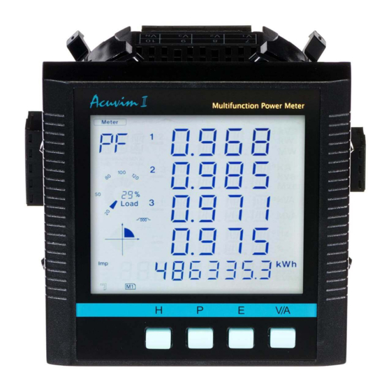
3.1 Display Panel and Keys The front of the Acuvim II series meter consists of an LCD screen and four control keys. All the display segments are illustrated in fig 3.1. Users should note that all the segments will not display in a single page under normal conditions. - Page 41 Display Description Shows different modes on the display area. “Meter” for real-time measurement; “Max/Min” for statistic Display mode indication data; “Demand” for power demand data; “Harmonic” for harmonic data; “Setting” for parameters setting; “Digital I/O” for expanded IO module data. Main display area: displays metering data such as voltage, current, power, power factor, frequency, Four lines of “...
- Page 42 voltage: V, kV; current: A, kA:active power: kW, MW; reactive power: kvar, Mvar; apparent power: kVA, MVA; Units measured frequency: Hz; active energy: kWh; reactive energy: kvarh; apparent energy: kVAh; percentage: %; phase angle: ° No icon: no communication Communication icon One icon: query sent Two icons: query sent and response received No icon: no pulse output...
-
Page 43: Metering Data
3.2 Metering Data Pressing H and V/A simultaneously will activate the display mode selection and the cursor will flash. Press P or E to move the cursor right or left. To enter the metering mode, move the cursor to "Meter" then press V/A. In the metering mode, press P and E simultaneously will enter the TOU mode. - Page 44 Note: When the meter is set to “2LL” or “3LL”, there is no phase voltage or neutral current display. Therefore, only the third screen (line voltage & avg) and the the fourth screen (three phase current & avg) will be displayed. b) Power, Power Factor and Frequency: Press P to display power related data.
- Page 45 E is pressed again. It will go back to the first screen if you press E at the last screen. Acuvim II series meter can be set to record primary energy or secondary energy.The unit of energy is kWh for active energy, kvarh for reactive energy and kVAh for apparent energy.
- Page 46 communication or from the meter front. The following figure shows the sequence: e) TOU display Press “P” and “E” simultaneously to enter the TOU Energy and maximum demand page. Press “E”display the TOU energy. Press “P”display the TOU maximum demand. Press again display the TOU maximum demand year,month and date. Press again display the TOU maximum demand hour, minute and second.
- Page 47 Sharp Import energy Sharp Import max demand Sharp Import max demand year/month/day Sharp Import max demand hour/min/sec ………. Sharp Export energy Sharp Export max demand ………. Sharp import reactive energy Sharp import reactive max demand ………. Sharp Export reactive energy Sharp Export reactive max demand Sharp Apparent energy Sharp Apparent max demand...
-
Page 48: Statistics Data
3.3 Statistics Data Pressing H and V/A simultaneously will activate the display mode selection and the cursor will flash. Press P or E to move the cursor right or left. To enter the statistics data mode, scroll the cursor to "Max/Min" then press V/A. In statistics data mode, the meter displays the maximum values and minimum values for voltage, current, power, power factor, unbalance, demand, THD etc. -
Page 49: Demand Data
Note: i) The figure shows the rolling sequence when pressing P. The sequence will be reversed when pressing E. ii) When the meter is set to “2LL” or “3LL”, the first screen(max value of phase voltage) will not be displayed. 3.4 Demand Data Pressing H and V/A simultaneously will activate the display mode selection and the cursor will flash. -
Page 50: Harmonic Data
3.5 Harmonic Data Pressing H and V/A simultaneously will activate the display mode selection and the cursor will flash. Press P or E to move the cursor right or left. To enter harmonic mode, move the cursor to "Harmonic" then press V/A. In the harmonic data mode, meter displays the harmonic ratio of voltage and current, THD, odd HD, even HD, THFF, CF and KF. - Page 51 b) Harmonic Ratio Data Press H to switch to power quality data display. The harmonic order will increase by one each time P is pressed and will return to the 2 when P is pressed at the 31 ) harmonic. Acuvim IIR/IIE/IIW The harmonic order will decrease by one each time E is pressed and will return to the 31...
-
Page 52: Expanded I/O Module Data
Note: The figure shows the rolling sequence when pressing P. If E is pressed, the sequence will reverse. 3.6 Expanded I/O Module Data Pressing H and V/A simultaneously will activate the display mode selection and the cursor will flash. Press P or E to move the cursor right or left. To access data from the expanded I/O modules, move the cursor to "Digital I/O"... - Page 53 a) Module Selection: No commands are associated with the key H in the module selection screen. Press P to move the cursor downwards, the cursor will move to the top when it reaches the bottom. If only one module is connected, Pressing P will have no effect.
- Page 54 Press E to move the cursor upwards, the cursor will move to the bottom when it reaches the top. Press V/A to select the parameter and enter the display of the data. c) I/O module data display Press H to return to I/O module data selection screen. The screen will roll to the next page each time P is pressed and will return to the first page when P is pressed at the last page.
-
Page 56: Parameter Settings Mode
Note: The figure shows the rolling sequence for using key P. If using E key for rolling page, the sequence will reverse. 3.7 Parameter Setting Mode Pressing H and V/A simultaneously will activate the display mode selection and the cursor will flash. Press P or E to move the cursor right or left. To enter parameter setting mode, move the cursor to "Setting"... - Page 57 communication address will display for 3 seconds. A four digit password (0000 to 9999) is required everytime before accessing the parameter setting mode. The default password is 0000. After entering the password, press V/A to go to the parameter selection page. The meter will return to the metering mode if a wrong password is entered.
- Page 58 Press E to move the cursor upwards, the cursor will move to the bottom when it reaches the top. Press V/A to select and modify the parameter.The figure shows the parameter selection page. “SYS” stands for system parameter, “I/O” stands for expanded I/ O module parameter, “NET”...
- Page 59 Key functions for modifying the parameter: Press H to move the flashing cursor to the next position. Press P to increase the number by 1. Press E to decrease the number by 1. Press V/A to confirm the modification and return to parameter selection mode. The following figure shows the sequence:...
- Page 61 Note: The figure shows the rolling sequence for usingthe P key. If using the E key for rolling page, the sequence will reverse.
- Page 62 d) Expanded I/O Module Parameter In the expanded I/O module parameter mode, user can choose to view the available modules that are attached to the meter and modify their parameters. If no expanded I/O modules are connected, the screen will display "NO IO". To return to system parameter setting mode main menu, press H (no commands are associated with other keys in this screen).
- Page 63 Key functions for modifying the parameter: Press H to move the flashing cursor to the next position. Press P to increase the number by 1. Press E to decrease the number by 1. Press V/A to confirm the modification and return to parameter selection mode. The following table shows the sequence:...
- Page 64 DI of AXM-IO2 can be used as the pulse counter, each DI function corresponds to one bit of a 4-bit register. The correspondence bit of 0 means that the DI works as the digital status input and the correspondence bit of 1 means that the DI works as the pulse counter. For example, if the setting value is 0001, it means that DI1 is set as the pulse counter and other DIs work as digital status inputs.
- Page 65 DI of AXM-IO3 can be used as the pulse counter, each DI function corresponds to one bit of a 4-bit register. The correspondence bit of 0 means that the DI works as the digital status input and the correspondence bit of 1 means that the DI works as the pulse counter. For example, if the setting value is 0001, it means that DI1 is set as the pulse counter and other DIs work as digital status inputs.
- Page 66 e) Ethernet Module Parameter In the Ethernet module parameter mode, user can view and modify the parameters. If no Ethernet module is connected, settings will have no effect. Key functions for finding the Ethernet module parameter: Press H to return to parameter selection mode. The screen will roll to the next page each time P is pressed and will return to the first page when P is pressed at the last page.
- Page 67 The selection of DHCP setting: MANU or AUTO Default setting: MANU IP address has four segments. Any segment can be set from 0~255. Default setting: 192.168.1.254 Submask has four segments. Any segment can be set from 0~255. Default setting: 255.255.255.0 Gateway has four segments.
- Page 68 f) Alarm Parameter In the alarm parameter mode, user can view and modify the parameters. Key functions for finding the alarm parameter: Press H to return to parameter selection mode. The screen will roll to the next page each time P is pressed and will return to the first page when P is pressed at the last page.
- Page 69 Yes: Alarm enable; No: Alarm disable It can be selected as cue signal for alarming. Yes: backlight flashes upon alarm condition; No: no backlight flashing There are 16 alarm channels available. Each channel is controlled and enabled 1 bit each from a 16-bit register. Bit value of 1 means that the corresponding alarm channel is enabled whereas 0 means that the channel is disabled.
-
Page 70: Page Recovery Function
3.8 Page Recovery Function Acuvim II series meter has a page recovery function. This means that the meter stores current display page in the non-volatile memory upon power loss and reloads the page when power recovers. If power goes off when viewing under the parameter setting mode, the meter will show voltage display when power recovers. -
Page 71: Chapter 4 Detailed Functions And Software
Chapter 4 Detailed Functions and Software 4.1 Basic Analog Measurements 4.2 Max/Min 4.3 Harmonics and Power Quality Analysis 4.4 Over/Under Limit Alarming 4.5 Data Logging 4.6 Time Of Use(TOU) 4.7 Power Quality Event Logging and Waveform Capture... - Page 72 The Acuvim II series meter contains advanced metering tools and is able to measure a multitude of power, energy and power quality parameters. Some advanced functions may not be accessible directly from the meter front; therefore, every meter comes with a powerful software that helps access the information.
- Page 73 Demand: This meter consists of several types of demand calculation: total active power demand, total reactive power demand, total apparent power demand, phase A current demand, phase B current demand, and phase C current demand. When demand is reset, demand memory registers are set as 0. Demand calculating mode can be set as sliding window and thermal according to user.
- Page 74 2. There are two ways to calculate reactive energy(power) Mode 0: real reactive energy Mode 1: general reactive energy 3. User can choose primary energy or secondary energy either by pressing keys from the meter front or via communication as shown in figure 4-7. Note: Acuvim IIR/llE/llW is able to display either primary energy or secondary energy on the LCD screen;...
- Page 75 Current direction adjustment Under normal circumstances, current flows from input terminal 1 to terminal 2 (i.e. from I11 to I12 for phase A current); however, current may flow in the opposite direction due to incorrect wiring setup. Instead of rewiring the system, the meter provides users an option to reverse the polarity of the current.
-
Page 76: Max/Min
They are shown in figure 4-4. 3. Sequence component and unbalance analysis Acuvim II series meter is able to perform sequential analysis for the input signal. It looks at the positive sequence, negative sequence and zero sequence of... -
Page 77: Over/Under Limit Alarming
Fig 4-4 Sequence component and Phase angle 4.4 Over/Under Limit Alarming Acuvim II series meter has over/under limit alarming capabilites. When the monitored parameter goes over/under the preset limit and stays at the level over the preset amount of time delay, the over/under limit alarm will be triggered. - Page 78 I/O modules are attached, digital outputs (DO) and relay outputs (RO) can be triggered upon alarm conditions and used to activate downstream devices such as a beacon light or a buzzer. Before using the alarming function, alarm conditions such as logic dependency, target setpoint, time delay etc must be set correctly.
- Page 79 1. Single Alarming Group Setting Table 4-1 indicates the first group of settings, there are 16 groups in total with the same format. Address Parameter Range Property 104eH First group: parameter code 0~50 104fH First group: comparison mode 1:larger,2:equal,3:smaller 1050H First group: setpoint value Related with parameters 1051H...
- Page 80 Note: If RO is under alarming mode, it can only work in “latch” mode. After setting up the alarming parameters, user must also setup the global settings in order for the alarm to work properly. 2. Global settings Register addresses for global alarm settings are from 1046H~104dH. Please refer to section 5.3, page 95 "Global alarming settings"...
- Page 81 disabled. “Alarming output to DO1 setting”: When “Digital output mode” is set to “1”, DO1 can be used as alarming output. A 16-bit register is used to perform this function, its bit0~bit15 correspond to the 1 group respectively. When the related I/O module is connected and is under alarming mode, and if the corresponding bit is set to 1 and the alarming condition is met, alarm signal will be sent to DO1.
- Page 82 “Output to relay (1052H)” is set to 0, because there is no output to RO. Settings of second group: “Parameter code (1053H)” is set to 1, which stands for U1. “Comparison mode (1054H)” is set to 3, which stands for "smaller than". “Setpoint value (1055H)”...
- Page 83 Acuvim II series meter has built in alarm logging capabilities. 16 entries can be recorded in total. The record sequence of these entries do not depend on the sequence of the 16 alarm channels. The meter begins logging alarm status starting from the 1 record location to the last one.
- Page 84 Alarming event will set bit0 of “system status (102eH)” to be 1. At the same time, corresponding flags will be set to 1 to indicate new data. The flag will be cleared after the data is read. Bit0 of “system status (102eH)” will be set to 0. Note: Although no alarming records will be lost during meter power off, alarm status will start recording from the 1 alarm log entry when meter is powered...
- Page 85 Fig 4-7 basic settings...
-
Page 86: Data Logging
4.5 Data Logging meter provides data logging that records the data at a set Acuvim IIR/IIE/IIW interval.This meter has 4 MegaBytes of memory which gives it extensive data- logging capabilities. It has a real-time clock that allows logs to be time-stamped when log events are created. - Page 87 Having three sets of historical logs provides you with the option of programming each log with unique parameters. For example, you can program Historical Log 1 to record measured values parameters (for example, Frequency, Voltage, Current), Log 2 to record energy values parameters, and Log 3 to record power quality parameters.
- Page 88 values) • AO/AI Value(the AO output values and the AI sample values) The following procedures show how to select and store parameters in historical log 1. The Group field determines the items that are available for selection. 1) Select a Group. The possible selections are: Real-Time Metering, Energy, THD Volts AN/AB, THD Volts BN/BC , THD Volts CN/CA , THD IA , THD IB , THD IC, Sequence Component, Phase Angles, DI Counter, AO/AI Raw Value and AO/AI Value.
- Page 89 within the specified time period. NOTES: • Data logging will stop when the allocated memory for the historical data log is full if the logging timer mode is enabled, no stored data will be erased in this mode. If the logging timer mode is disabled then when the historical data log is full, the first sector of this log will be erased and overwritten by the latest records.
- Page 90 Fig 4-9 Retrieval screen The "read one window" method allows you to access and read a specific log location at an offset from the first log. The "window record num" is the maximum number of record entries the software can read at a time, it is calculated by 246 / Record Size.
-
Page 91: Time Of Use (Tou)
4.6 Time of use (TOU) User can assign up to 4 different tariffs (sharp, peak, valleyand normal) to different time period within a day according to the billing requirements. The meter will calculate and accumulate energy to different tariffs according to the meter’s internal clock timing and TOU settings. - Page 92 year (the earlier date comes first and the later date comes last). For example, if 3 seasons are selected, the date parameters are January 1, June 6 and September 7, and TOU schedule 02, 01, 03 will be used respectively, the first TOU season table slot shall enter 01-01 02, the second slot shall enter 06-06 01, and the third slot shall enter 09-07 03.
- Page 93 6. Tariff setting parameter: This parameter corresponds to the number of tariffs available for the TOU calendar and can be selected from any integer from 0 to 3. The four tariffs: sharp, peak, valley and normal are represented by 4 integers: 0, 1, 2 and 3 respectively.
- Page 94 By using the function, you can cause the instrument to automatically switch to and from daylight saving time. When the clock starts to run to daylight saving time, the meter will automatically adjust the clock to a time period in advance, while the clock is running to the end of daylight saving time, meter will automatically adjust the clock pushed back to a time period, as shown in Fig 4-10...
- Page 95 next decade will be generated. Holiday Auto Switch: When Ten-year Holiday is enabled, if the current year of the meter falls into the Ten-year Holiday setting, it automatically loads the Ten- year Holiday settings into the current TOU settings. If the current year of the meter does not fall into the Ten-year Holiday setting, it remains the current TOU settings.
- Page 96 as 3, it means both Saturday and Sunday effective. When Weekend schedule is enabled, bit0 means Sunday; bit1~bit6 mean Monday to Saturday. When the meter clock is within the period of weekly interval, energy will accumulate to the tariff associated with the weekend schedule setting. The software takes in decimal number for weekend setting.
-
Page 97: Power Quality Event Logging And Waveform Capture
2.Assigned Clock: User can select when the values from Current Month TOU would be copied over to Prior Month TOU. User can set the time in the following format “DD HH: MM: SS” - DD stands for day, HH stands for hour, MM stands for minute, SS stands forsecond. - Page 98 must clear the event log, and then the logging will log the new event. When the log is cleared, the new event will be logged from the first event happening. There will be no data loss after the power is off. 3.
- Page 99 4. Event Log Retrieve When a new event log commences, the newest event number address(0X8CFDH)contains the newest event number. When the log is being retrieved, the starting event log number (0X8CFEH) and the event quantity for each retrieve (0X8CFF) must be set correctly. It must be ensured that the starting number of event log should equal or smaller than the newest log number.
- Page 100 event log retrieve page is in the figure below. The Modbus register address of the event log is in the table below (see details in Chapter 6). 8CFDH The newest event number word Range: 1~50000 0: No event 8CFEH The starting event log number word R/W Range: 1-50000 Note: smaller than or...
- Page 101 1. Waveform Capture Data Format Timestamp(7 words)+ Triggering Condition(9 words)+ U1, U2, U3, I1, I2, I3(Before triggering point 8 waveforms 32 x 8 x 6 words)+ U1, U2, U3, I1, I2, I3(After triggering point 8 waveforms 32x8x6 words). Timestamp: Year( W1), Month( W2), Day( W3), Hour( W4), Minute( W5), Second(W6), Millisecond(W7) Triggering Condition: W8—Manual Triggering (0: disable;...
- Page 102 2. Waveform Capture Group Waveform Capture can log up to8 groups of waveform data. When the 8 group data is full, it does not respond to any waveform triggering condition. Only when all the waveform data is reset / emptied, waveform capturing function will be normal.
- Page 103 Waveform is enabled, both event logging and waveform capture will be implemented at the same time once a voltage sag happens. 4) Voltage Swell Triggering As mentioned in Voltage Swell event logging, when Voltage Swell Triggering Waveform is enabled, both event logging and waveform capture will be implemented at the same time once a voltage swell happens.
- Page 104 secondary side value. The waveform capture retrieve page is shown in Figure 4-13.
-
Page 105: Chapter 5 Extended Modules
Chapter 5 Extended Modules 5.1 IO Modules 5.2 Ethernet Module (AXM-NET) 5.3 ProfiBus Module (AXM-PRO) 5.4 RS485 Module (AXM-485) -
Page 106: Io Modules
According to the diference in communication with Acuvim II meter, each type of IO module also has two modes, logic NO.1 and logic NO.2. This means, two of each type of IO module can be linked to the Acuvim II meter simutaneously (one being logic NO.1 and the other being logic... - Page 107 The AXM-IO2 module is composed of: 4 digital inputs (DI) -- Each digital input can be used to detect remote signals, or be used an input pulse counter. When it is used to detect remote signals it can also enable SOE(sequence of events), recording the events and time of the events.
- Page 108 5.1.2 List of Functions of IO Modules Functions AXM-IO1 AXM-IO2 AXM-IO3 Detection of remote signals Recording of SOE Counting of input pulses Output remote controlling by relay Output alarm by relay Output alarm by digital output Output power pulses by digital output Analog output Analog input 24V isolated voltage output...
- Page 109 5.1.3 Appearance and Dimensions 90.00 Enclosure Installation screw Wiring Terminals Counterpart of clip Linking pins Installation clip Linking socket Fig 2-1 Dimensions 5.1.4 Installation Method Environment Please verify the installation environment meets the requirements listed as follows:...
- Page 110 Humidity 5% to 95% non-condensing. Location The Acuvim II meter and IO modules should be installed in a dry and dust free environment avoiding heat, radiation and high electrical noise sources. Installation Method With the link pins, IO modules are linked to the meter and to each other. The maximum number of extended modules linked to Acuvim II meter, including IO module, Ethernet module and PROFIBUS module, is three.
- Page 111 Fig 5-2 Installation of IO modules 5.1.5 Wiring of IO Modules Terminal strips of AXM-IO1 modul Digital Input Relay Output RO1 RO2 V– Fig 5-3 Terminal strips of AXM-IO1 module DI1 to DIC: digital input terminals, where DIC is the common terminal for DI1 to DI6 circuits.
- Page 112 Terminal Strips of AXM-IO2 Module: Digital Input Digital Output Analog Output AO1+ AO1– AO2+ AO2– DO1 DO2 DOC Fig 5-4 Terminal strips of AXM-IO2 module DI1 to DIC: digital input terminals, where DIC is the common terminal for DI1 to DI4 circuits.
- Page 113 Sequence of DI, RO, DO, AO, AI in IO modules (according to the logical order in the communication address table of the main body): DI Sequence: AXM-IO11 (AXM-IO1 module in logic NO.1): DI1-6 AXM-IO21 (AXM-IO2 module in logic NO.1): DI7-10 AXM-IO31 (AXM-IO3 module in logic NO.1): DI11-14 AXM-IO12 (AXM-IO1 module in logic NO.2): DI15-20 AXM-IO22 (AXM-IO2 module in logic NO.2): DI21-24...
- Page 114 circuits in AXM-IO1, AXM-IO2 and AXM-IO3 modules respectively. The digital input circuit can be used to detect remote signals, or be used as an input pulse counter. Optical coupler Electrical 0V AC /DC Adjuster IO module Fig 5-6 schematic diagram of digital input circuit The circuit drawing of digital input is simplified as shown in Figure 5-6.
- Page 115 mediate relay External power supply control IO module coil output Fig 5-7 schematic diagram of relay output circuit The wire of relay output should be chosen between AWG22~16 or 0.5~1.3mm Wiring of Digital Output Circuit: There are 2 digital output circuits in AXM-IO2 module. The digital output circuit can work in alarm state, or work in energy pulse output state.
- Page 116 When J is in low state as shown in Figure 5-8, OUT is in low state. When J is in high state, OUT is in high state. OUT can therefore output pulse signals under the control of J. The max output voltage and current of digital output circuit are 250V and 100mA respectively.
- Page 117 The simplified circuit is as shown in Figure 5-10. load load Current analog output Voltage analog output Fig 5-10 schematic diagram of analog output circuit The Load Capability of Analog Output Circuit: 0 to 20mA mode: the max load resistance is 500Ω. 4 to 20mA mode: the max load resistance is 500Ω.
- Page 118 Figure 5-12 shows the function of IO modules, which is displayed in the utility software as follows, where AXM-IO12 (AXM-IO1 module in logic NO.2), AXM- IO22 (AXM-IO2 module in logic NO.2) and AXM-IO32 (AXM-IO3 module in logic NO.2) are linked to Acuvim II meter.
- Page 119 Fig 5-12 functions of IO modules 5.1.6 Detection of Remote Signals The digital input circuit can be set to detect remote signals. a. Detection of Remote Signals When digital input circuit detects a qualified voltage input, it will show “1” on screen and “ON”...
- Page 120 SOE records are generated, the records will begin at the first one. When the Acuvim II meter is powered on, the SOE begins to record immediately. The data in the SOE records will not be lost if the meter is powered off. When...
- Page 121 All groups of SOE records are in the same format. Take the first group of SOE records for example, “4399H to 439fH” registers record the time information, including year, month, day, hour, minute, second and millisecond. “43a0H” register records the state information, which is an unsigned integer, where bit 0 records DI1 state, bit 1 records DI2 state, and so on.
- Page 122 NO.2) is SOE enabled. Only one IO module can be SOE enabled at one time. If the IO module is not linked to the Acuvim II power meter, then there is no need to enable SOE function in the software.
- Page 123 Fig 5-15 parameters setting of IO module’s SOE function 5.1.7 Pulse Counter The digital input circuit can also be set to count pulses. Recorded number of pulses: including “4349H to 4380H” address The “4349H to 4380H” registers record 28 groups of individual number of individual number of pulses.
- Page 124 NO.1), 4 groups of records for AXM-IO21 (AXM-IO2 module in logic NO.1), 4 groups of records for AXM-IO31 (AXM-IO3 module in logic NO.1), 6 groups of records for AXM-IO12 (AXM-IO1 module in logic NO.2), 4 groups of records for AXM-IO22 (AXM-IO2 module in logic NO.2) and 4 groups of records for AXM- IO32 (AXM-IO3 module in logic NO.2) in sequence.
- Page 125 Fig 5-17 recorded number of pulses read by the utility software Parameter Settings for Counting Input Pulses: Take AXM-IO11 (AXM-IO1 module in logic NO.1) for example. 1. “109eH” register: if the bit is set as “1”, the counterpart digital input circuit is set to be a counter of input pulses.
- Page 126 Real number of pulses = A × Recorded number of pulses. For example, if A=20, the recorded number of pulses counted by DI1 circuit of AXM-IO11 is 100 (4349H to 434aH registers), then the real number of pulses is 20×100=2000. The parameter setting is shown in Figure 5-13.
- Page 127 Fig 5-18 status of relays read on screen b. Parameter Setting Take AXM-IO11 (AXM-IO1 module in logic NO.1) for example. “RO working mode (10a0H)” register: this register determines the working mode of relays. If the register is “0”, then RO1 and RO2 will work in controlling mode.
- Page 128 5.1.9 Digital Output There are two mode selections for the digital output circuit; one being alarm mode, and the other being energy output mode. For alarm mode, action of digital output circuit is controlled by whether the alarm is triggered or not. For energy output mode, digital output circuits can output various types of energy, such as import active energy, export active energy, import reactive energy and export reactive energy.
- Page 129 “DO1 output type” register and “DO2 output type” register can be set to the same value or not. The parameter setting is shown in Figure 5-19. Fig 5-19 parameter setting of DO energy pulse constant When DO circuits work in energy output mode, parameters of DO energy pulse constant should also be set correctly.
-
Page 130: Analog Output
The value of pulse constant should satisfy following formula(Only used in Acuvim II): DO Pulse Width Pmax Pulse constant >( +1) × 18×10 In the formula, “Pmax” is the maximum power or reactive power. The unit is watt or var. Recommend pulse constant is 3 to 5 times the right side value of the above expression. - Page 131 |PT1 |1.2PT1 |3PT1 |3.6PT1 1.2PT1 1.2PT1 PT1 1.2* CT1 1.2CT1 3PT1 3.6PT1 |±0.5| |±1| *CT1 *CT1 *CT1| *CT1| *CT1| *CT1| *CT1 *CT1 Total Apparent Phase Active/Reactive Frequency(Hz) Total Active/Reactive Phase Apparent Phase Voltage(V) Line Voltage(V) Current(A) Power Factor Power(VA) Power(W/Var) Power(W/Var) Power(VA) 0-5V output mode...
- Page 132 As shown in Figure 5-21, the displayed value of AO1 is 0x0800, so the real value of AO1 is (0x0800/4096) ×5V or (0x800/4096) ×20mA. Fig 5-21 AO value read on screen 3. Parameter Setting Take AXM-IO21 (AXM-IO2 module in logic NO.1) for example. “Electrical quantities relative to AO1 (10c2H)”...
- Page 133 Fig 5-22 Parameter setting of IO modules...
- Page 134 5.1.11 Analog Input Analog input circuits supply 4 types of input modes, including 0 to 20mA mode, 4 to 20mA mode, 0 to 5V mode, and 1 to 5V mode. Figure 5-23 shows the relationship between AI value and input analog value. AI value ranges from 0 to 4095 without any unit.
-
Page 135: Ethernet Module (Axm-Net)
5.2 Ethernet Module (AXM-NET) 5.2.1 Introduction to Ethernet Ethernet was originally developed by Xerox and then developed further by Xerox, DEC, and Intel. Ethernet uses a Carrier Sense Multiple Access with Collision Detection (CSMA/CD) protocol, and provides transmission speeds up to 10 Mbps. - Page 136 5.2.3 Appearance and Dimensions 22mm (Side View) 90mm 55.6mm (Top View)
- Page 137 (Bottom View) 5.2.4 Installation Method The Ethernet module is linked to the Acuvim II meter by a communication plug. It can also be linked to other extended modules like IO modules. 1.Insert the installation clips to the counterpart of the meter, and then press the Ethernet module lightly, so linking is established.
- Page 138 Note: 1. Install Ethernet Module carefully to avoid damage; 2. Under no circumstances should any installation be done with the meter powered on. Failure to do so may result in injury or death. 5.2.5 Definition of RJ45 Interface The Ethernet module uses a standard RJ45 connector to access the Ethernet network.
- Page 139 LED_L (yellow): displays speed status. LED on indicates 100Mbps, while LED off indicates 10Mbps. LED_R (green): displays link and activity status combined. LED on indicates link status, while flashing LED indicates activity status. 5.2.6 Cable Shielded twisted-pair cable (standard 568A or standard 568B) is usually recommended as reference to the EIA/TIA standard.
- Page 140 1. Pressing “H” key and “V/A” key simultaneously on the meter will go to the menu selecting mode. Cursor “Meter” flashes in this mode. Fig 5-25...
- Page 141 2. Press “P” key or “E” key to move the cursor to "Setting". Press “V/A” key to go to the meter parameter setting mode. Device address page is the first page of “Setting” mode. It shows the Modbus address of the device for several seconds, and then the screen goes to Access Code page.
- Page 142 Fig 5-27 Fig 5-28...
- Page 143 3. Set configuration mode in the first setting page. “AUTO” means that users configure module settings with DHCP protocol while “MANU” means that users configure module settings with manual setting. Press “V/A” key, to go to the setting state and the area pointed out in Figure 5-29 will flash. Press “P” key or “E”...
- Page 144 Fig 5-30 5. Set Subnet Mask in the third setting page, such as 255.255.255.0. Press “V/A” key to go to the setting page. Users may set the parameters in the area pointed out in Figure 5-31. The cursor starts at the first digit. After setting the Subnet Mask, press the "V/A"...
- Page 145 6. Set Gateway in the fourth setting page, such as 192.168.1.1. Press the "V/ A" key to go to the setting page. Users may set the parameters pointed out in Figure 5-32. The cursor starts at the first digit. After setting the Gateway, press the "V/A"...
- Page 146 7. Set DNS Primary Server in the fifth setting page, such as 202.106.0.20. Press the "V/A" key to go to the setting page. Users may set the parameters pointed out in Figure 5-33. The cursor starts at the first digit. After setting the DNS Primary Server, press the "V/A"...
- Page 147 8. Set DNS Secondary Server in the sixth setting page, such as 202.106.196.115. Press the "V/A" key to go to the setting page. Users may set the parameters pointed out in Figure 5-34. The cursor starts at the first digit. After setting the DNS Secondary Server, press the "V/A"...
- Page 148 9. Set Modbus-TCP port in the seventh setting page, such as 502. Press the "V/ A" key to go to the setting page. Users may set the parameters pointed out in Figure 5-35. The cursor starts at the first digit. After setting the Modbus-TCP port, press the "V/A"...
- Page 149 10. Set HTTP port in the eighth setting page, such as 80. Press the "V/A" key to go to the setting page. Users may set the parameters pointed out in Figure 5-36. The cursor starts at the first digit. After setting the HTTP port, press the "V/ A"...
- Page 150 Fig 5-37 12. The password of AXM-NET module can be reset by selecting " RESET". The password then becomes "12345678". Selecting "NO" means no change. Press "V/A" key to accept. Fig 5-38 13. After configuring AXM-Net settings completely, press “H” key and “V/ A” key simultaneously to return to menu selecting mode.
- Page 151 5.2.9 Searching IP Address of Ethernet Module The utility software of Acuvim II series meter supports a meter search function. Users can use this function to obtain IP and MAC addresses of Ethernet Modules. Operation steps: 1) Click “Start” menu of utility software.
- Page 152 3) Utility software pop-ups “Search Device(s)” window, and the window displays IP address and MAC address of module. Fig 5-40 Note:This function is used only in LAN, not used in WAN or direct connect to computer. 5.2.10 Description of Modbus-TCP protocol The Modbus-TCP protocol is used for communication in Ethernet modules.
- Page 153 Request Indication Modbus Client Modbus Server Confirmation Response Fig 5-41 1. Protocol a. Data Frame Format MBAP Header Function Data 7x8-Bits 8-Bits Nx8-Bits Table 5-1 b. Modbus Application Header (MBAP Header) Field The Modbus application header field is the start of the data frame and consists of seven bytes.
- Page 154 Code Meaning Action Read Relay Output Status Obtain current status of Relay Output Read Digital Input(DI) Status Obtain current status of Digital Input Read Data Obtain current binary value in one or more registers Control Single Relay Output Force Relay to a state of on or off Place specific value into a series of consecutive Write Multiple-registers multiple-registers...
- Page 155 Data #of regs lo: number of register low byte a. Read Status Relay (Function Code 01) Function Code 01 This function code is used to read relay status in Acuvim II series meter. 1=On 0=Off There are 8 Relays in the meter, and the starting address is 0000H.
- Page 156 Table 5-5 Read 2 Relays Status Query Message Response The Acuvim II series meter response includes MBAP Header, function code, quantity of data byte and the data. For example response to read the status of Relay 1 and Relay 2 is shown as Table 5-6. The status of Relay 1 and Relay 2 is responding to the last 2 bit of the data.
- Page 157 Read Status of DI (Function Code 02) Function Code 02 1=On 0=Off There are 38 DIs in the meter, and the starting address is 0000H. The following query is to read the 4 DIs Status of address 1 of Acuvim II series meter. Query Transaction Transaction...
- Page 158 Table 5-8 Read 4 DIs Response Message c. Read Data (Function Code 03) Query This function allows the users to obtain the measurement results of Acuvim II series meter. Table 5-9 is an example of reading the 6 measured data (Time) from server device address 1, the data start address is 1040H.
- Page 159 The message forces a single Relay either on or off. Any Relay that exists within the Acuvim II series meter can be forced to be either status (on or off ). The address of Relay starts at 0000H, and the meter has eight Relays.
- Page 160 Function code 16 allows the user to modify the contents of a Multi-Register. The example below is a request to an Acuvim II series meter address 1 to Preset CT1 (500) and CT2 (5). CT1 data address is 1008H, and CT2 data address is 1009H.
- Page 161 Table 5-14 Preset Multi-Registers Response Message Users may refer to the sixth chapter “Communication” and get the details of Acuvim II series meter. When using Modbus/TCP function, it is best to set the Scan interval of the software to under 1000 ms.
- Page 162 5.2.11 Webpage Browsing and Parameter Settings The Ethernet module supports HTTP protocol and has a Web Server function making the Acuvim II series meter accessible through Ethernet at anytime from anywhere. The Ethernet module supports IE Browser 6.0 and higher editions and the Webpage Settings only support ASCII characters.
- Page 163 2. Module Status Webpage By selecting the "Module Status" link, users can view the status and change the settings of the Ethernet module. Fig 5-43...
- Page 164 3. Settings Webpage By selecting the "Settings" link, users can access "Network Settings", "Mail Settings", "Webpage Settings", "Load Default" and "Password Setting". When accessing the "Settings" link, users will be prompted to enter a password. The default password is 12345678. a.
- Page 165 b. “Network Settings” Webpage Figure 5-45: “Network Settings” webpage. It supports two network setting modes: Manual or Auto. There are two port settings: HTTP port and Modbus- TCP port. The default value of Modbus-TCP port is 502, and the user defined range is 2000~5999.
- Page 166 Note: Mail Server part includes "SMTP Server", "User Name" and "Password". For the "SMTP Server" users can input either domain name such as "mail. accuenergy.com" or an IP address such as "222.128.6.73" which is from "mail. accuenergy.com" resolved. A user name and password will be required to log in.
- Page 167 Fig 5-46...
- Page 168 d. "Web Configuration Settings" Webpage Figure 5-47: "Webpage Settings" page. Users set the "Device Description" according to the meter type. Languages supported are English and Simplified Chinese. Fig 5-47 e. “Load Default” Webpage Figure 5-48: "Load Default" webpage. The "Reset AXM-NET module" option resets the module itself.
- Page 169 DNS Primary: 202.106.0.20 DNS Secondary: 202.106.196.115 MODBUS Port: 502 HTTP Port: 80 Fig 5-48...
- Page 170 f. “Password Setting” Webpage Figure 5-49: “Password Setting” webpage.To change the password, users need to input the current password first. Fig 5-49...
- Page 171 "Metering" webpage includes the data of real-time parameters for Acuvim II series meter. There are thirty nine parameters, such as Volts AN, I A, Watt A. "Energy" webpage includes the energy data for Acuvim II series meter. There are nine parameters, such as Delivered kWh, kVAh.
- Page 172 VB to VA. "Max and Min" webpage includes the max and min data of parameters for Acuvim II series meter. There are twenty-five parameters, such as Volts AN, I A , and Watt Total (Demand). "Alarm Record" webpage includes alarm records for Acuvim II series meter. There are sixteen records.
-
Page 173: Profibus Module (Axm-Proi)
5.3 ProfiBus Module (AXM-PRO) 5.3.1 Introduction of PROFIBUS Technology PROFIBUS (Process Field bus) is an international field bus standard which is widely used in automation technology of manufactures and flow industry. It is a widely used, open digital communication system, which is suitable for high- speed, time-critical, and high reliability communications. - Page 174 module as well. * The PROFIBUS module can only be used as slave in PROFIBUS network. Its slave address ranges from 0 to 126, which can only be set by the panel. If the address is changed, it will take effect immediately. * The PROFIBUS module’s baud rate can be adaptive between 9.6Kbps to 12Mbps in PROFIBUS network.
- Page 175 5.3.3 Appearance and Dimensions 90mm 55.6mm (Top View) (Bottom View)
- Page 176 (Side View) 5.3.4 Installation Method PROFIBUS is linked to Acuvim II meter by communication plug. It can also be linked to other extended modules such as IO modules. 1. Insert the installation clips to the counterpart of Acuvim II meter, and then press the PROFIBUS module lightly, so linking is established.
- Page 177 5.3.5 Definition of DP Interface The PROFIBUS module uses standard 9-pin D-type connector to access PROFIBUS network. The mechanical and electrical characteristics of connector are consistent with the requirements of IEC 807-3. The connector of PROFIBUS is a socket, and the counterpart connector of cable is a plug. Connector pins are distributed as follows: Pins RS-485...
- Page 178 STATION 3 STATION 4 STATION 1 STATION 2 DGND DGND Connection of many DP stations The bus terminal is composed of three resistors and connection wire, where Vp is the supply positive voltage and DGND is the Digital Ground. When the bus is idle, the bus terminal makes the data P level higher than data N, so the bus’s idle signal is always 1.
- Page 179 The PROFIBUS module can only be used as a slave in the PROFIBUS network. Its slave address ranges from 0 to 126, which can only be set by the front panel of the meter (in SYS sub menu of Acuvim II Setting menu). If the address is changed, it will take effect immediately.
- Page 180 The PROFIBUS module’s data interface is a 16 word input/output interface. 5.3.11 Information Exchange A variety of information from the Acuvim II meter can be transmitted by the PROFIBUS module, such as electrical quantities and other parameters. The basic communication method of the Acuvim II meter is RS-485, which uses protocol of MODBUS-RTU.
- Page 181 II meter and the real physical value. 3. Different parameters may have different data length and data type. These three points are also suitable for the PROFIBUS-DP protocol in PROFIBUS module. Note: the following “communication formats”are suitable for the application data, but not for the PROFIBUS-DP’s frame characteristic data.
- Page 182 Response Below is the response that a slave device would send to a master. Frame Bytes Caption Byte1 The channel of inquiry frame Byte2 Byte3 byte count Byte4 coil status Byte5~32 The coils in the response message are packed as one coil per bit of the data field. Status is indicated as 1=ON and 0=OFF.
- Page 183 5.3.13 Format of function code 05H The message with function code (05H) in MODBUS-RTU forces a single relay either on or off. The data value FFOOH will set the relay on and the value 0000H will turn it off. All other values are invalid and will not affect that relay. In PROFIBUS-DP, the format of function code 05H is defined as follows: Quer y Frame Bytes...
- Page 184 Example: setting Relay2 on. Query Byte1 Byte2 Byte3 Byte4 Byte5 Byte6 Byte7~32 Response Byte1 Byte2 Byte3 Byte4 Byte5 Byte6 Byte7~32 5.3.14 Format of function code 02H Function code 02H is used to read DI status in MODBUS-RTU. In PROFIBUS-DP, the format of function code 02H is defined as follows: Query Frame Bytes Caption...
- Page 185 The digital inputs in the response message are packed as one input per bit of the data field. Status is indicated as 1=ON; 0=OFF. The LSB of the first data byte contains the input addressed in the query. The other inputs follow toward the high order end of this byte, and from low order to high order in subsequent bytes.
- Page 186 5.3.15 Format of function code 03H This function code is used in MODBUS-RTU to read the contents of a continuous block of holding registers in Acuvim II meter. In PROFIBUS-DP, the format of function code 03H is defined as follows:...
- Page 187 Chapter 6. 5.3.16 Format of function code 10H This function code is used in MODBUS-RTU to write a block of continuous registers in the Acuvim II meter, such as system parameters setting and so on. In...
- Page 188 PROFIBUS-DP, the format of function code 10H is defined as follows: Query Frame Bytes Caption Byte1 Byte2 Byte3 starting address high byte Byte4 starting address low byte Byte5 quantity of registers high byte Byte6 quantity of registers low byte Byte7 byte count Byte8 register value 1 high byte...
- Page 189 Frame Bytes Caption Byte1 Byte2 Byte3 starting address high byte Byte4 starting address low byte Byte5 quantity of registers high byte Byte6 quantity of registers low byte Byte7~32 Example: presetting import active enengy (EP_imp) to 17807783.3Kwh. Based on the relationship between the register value and the physical value, we can get that the register value in hex is 0A9D4089H.
-
Page 190: Rs485 Module (Axm-Rs485)
5.4.2 Function Description of RS485 module AXM-RS485 module uses RS485 serial communication and the Modbus-RTU protocol, just like the onboard RS485 port of the Acuvim II series meter. It provides a second RS485 port for serial communication, and it can be working with the onboard RS485 serial communication simultaneously. - Page 191 • Use good quality shielded twisted pair cable, AWG22 (0.5mm ) or higher. • The overall length of the RS485 cable connecting all devices should not exceed 1200m (4000ft). • Every A(+) should be connected to A(+), B(-) to B(-), or it will influence the network, or even damage the communication interface.
- Page 192 (bottom View) 5.4.4 Installation Method The RS485 module is linked to the meter by a communication plug. It also can be linked to other extended modules. 1.Insert the installation clips to the counterpart of the meter, and then press the RS485 module lightly, so linking is established.
- Page 193 The default baud rate of RS485 module is 38400 bps. Users can change the baud rate in system settings S03 of the Acuvim II series meter. The data format is start bit + 8n data bit + parity + stop bit. NON1, NON2, odd and even can be selected for parity mode on S32 of Setting page of Acuvim IIR and Acuvim IIE meter (Not support Acuvim II meter).
- Page 194 non-parity, single stop bit; NON2 represents non-parity, double stop bit; odd represents odd-parity, single stop-bit; even represents even parity, single stop bit; As is shown, the RS485 module’s parity is set as None 2. Please note: if AXM-NET is used, RS-485 module’s parity (PAR2) must be set as None1 in order to have the meter recognize the AXM-NET.
-
Page 195: Chapter 6 Communication
Chapter 6 Communication 6.1 Modbus Protocol Introduction 6.2 Communication Format 6.3 Data Address Table and Application Details 6.3.1 System Parameter Setting 6.3.2 System Status Parameter 6.3.3 Date and Time Table 6.3.4 Over/Under Limit Alarming Setting 6.3.5 I/O Modules Settings 6.3.6 Metering Parameter Address Table 6.3.7 Data Logging 6.3.8 Time of use... - Page 196 6.1 Modbus Protocol Introduction Modbus RTU protocol is used for communication in Acuvim II series meters. Data format and error check methods are defined in Modbus protocol. The half duplex query and respond mode is adopted in Modbus protocol. There is only one master device in the communication network.
- Page 197 addresses are in the range of 0~247 decimal. A master addresses a slave by placing the slave address in the address field of the message. When the slave sends its response, it places its own address in this address field of the response to let the master know which slave is responding.
- Page 198 in the data field, and the data to be written into the registers. If no error occurs, the data field of a response from a slave to a master contains the data requested. If an error occurs, the field contains an exception code that the master application can use to determine the next action to be taken.
- Page 199 of the register, after all the bytes of the message have been applied, is the CRC value. When the CRC is appended to the message, the low-order byte is appended first, followed by the high-order byte. 6.2 Communication Format Explanation of frame Data start Data start Data #of...
- Page 200 2. Read Status of DI Function Code 02 1=On 0=Off DI1’s address is 0000H, DI2’s address is 0001H, and so on. The following query is to read the Status of 4 DIs of Acuvim II series meter with communication address 17.
- Page 201 This function allows the master to obtain the measurement results from the Acuvim II series meter. Table 6.8 is an example of reading the measured data (F, V1 and V2) from slave device number 17, the data address of F is 4000H, 4001H;...
- Page 202 The data value FF00H will set the relay on and the value 0000H will turn it off; all other values are invalid and will not affect that relay. The example below is a request to the Acuvim II series meter with the address of 17 to turn on Relay1.
- Page 203 Acuvim II series meter can have their contents changed by this message. The example below is a request to an Acuvim II series meter with the address of 17 to preset Ep_imp as "17807783.3KWh", while its HEX value is 0A9D4089H.
- Page 204 6.3 Data Address Table and Application Details There are several rules to follow in using the meter: 1. Data type: “bit” refers to binary. “word” refers to 16-bit unsigned integer using one data address and 2 bytes of memory, it varies from 0 to 65535. “int”...
- Page 205 Parameters Relationship Unit Format code Numerical value equals to System parameters No unit communication value Run time T=Rx/100 Hour N u m e r i c a l va l u e e q u a l s to Clock Unit of time communication value Energy(primary)
- Page 206 1. When function code 10H is used, one communication command can only modify contents in one region, such as “System parameters settings”, ”System status parameter”, “Date and Time table”, “Over/under limit alarming-Global settings”, “Over/under limit alarming-Single settings”, “I/O Modules settings”, Data logging 1 settings,Data logging 2 settings,Data logging 3 settings.
- Page 207 100bH kvarh pulse constant 1~6000 word 100cH LCD backlight time 0~120 word 100dH Demand slid window time 1~30 word 1:sliding window 100eH Demand calculating mode word 2:thermal 100fH Clear demand memory Only 1 works word 1010H Max/Min clear Only 0AH works word 1011H Run time clear Only 1 works...
- Page 208 1035H Run time (low) word Bit0: AXM-IO11; Bit1: AXM-IO12; Bit2: AXM-IO21; Expanded Bit3: AXM-IO22; 1036H IO Modules word Bit4: AXM-IO31; connecting status Bit5: AXM-IO32; 0: disconnected 1: connected only Acuvim II has this 1037H Temperature word address 1038H~103eH Reserved word...
- Page 209 Please refer to Chapter 3 and Chapter 4 for more details about parameter settings. 6.3.3 Date and Time Table Function code: 03H for reading, 10H for presetting. Address Parameter Format code Range Data type Property 103fH week word 1040H Year 2000-2099 word 1041H...
- Page 210 0~255 Bit0: first logic switch Logic “And ” between alarming 1:enable;0:disable 1049H word setting Bit1: second logic switch …… Bit7: eighth logic switch 0~65535 Bit0: channel 1 output 1:enable;0:disable 104aH Alarming output to DO1 setting word Bit1: channel 2 output ……...
- Page 211 Alarming parameter code table Setting Setting Setting Alarming object Alarming object Alarming object value value value Frequency Average phase voltage Average line voltage Line current of Line current of Line current of phase phase A phase B Average line Neutral current Power of phase A current Power of phase B...
-
Page 212: I/O Modules Settings
6.3.5 I/O Modules Settings I/O module setting changes will be made only if the corresponding I/O modules are installed, no changes will be made otherwise. Please check the I/O module connection status before doing any settings. Function code: 03H for reading, 10H for writing. - Page 213 0: none 1: consumption power 10a7H DO1 output 2: gererating power word 3: absorption reactive power 4: generating reactive power 10a8H DO2 output Same as above word 0: 0~20mA, 1: 4~20mA, 10a9H AO1,2 type 1 or 2 word 2: 0~5V, 3: 1~5V AXM-IO31 Address Parameter...
- Page 214 AXM-IO22 Address Parameter Default Range Data type Property Bit0: DI21, Bit1: DI22, 10b5H DI21~24 type Bit2: DI23, Bit3: DI24 word 0: DI, 1: pulse counter 10b6H DI pulse constant 1~65535 word W o r k i n g m o d e o f 0: pulse output, 10b7H word...
- Page 215 Address Parameter Default Range Data type Property AO1 transforming 10c2H Refer to following table word parameter AO2 transforming 10c3H Refer to following table word parameter AO3 transforming 10c4H Refer to following table word parameter AO4 transforming 10c5H Refer to following table word parameter AO transforming parameter settings...
-
Page 216: Metering Parameter Address Table
In secondary mode, the relationship between the numerical value in the register and the real physical value is shown in the following table. (Rx is the numerical value in register of Acuvim II series meter) Function code: 03H for reading. Data... - Page 217 Phase A reactive 4024H~4025H Q=Rx×(PT1/PT2)×(CT1/CT2) float power Qa Phase B reactive power 4026H~4027H Q=Rx×(PT1/PT2)×(CT1/CT2) float Phase C reactive 4028H~4029H Q=Rx×(PT1/PT2)×(CT1/CT2) float power Qc System reactive power 402aH~402bH Q=Rx×(PT1/PT2)×(CT1/CT2) float Qsum Phase A apparent 402cH~402dH S=Rx×(PT1/PT2)×(CT1/CT2) float power Sa Phase B apparent 402eH~402fH S=Rx×(PT1/PT2)×(CT1/CT2) float...
- Page 218 Real time energy measurement Data stored in this block can be preset or cleared. Function code: 03H for reading, 10H for writing. Data type: dword. It can be set as primary energy or secondary energy according to user. Please refer to F7, F8, and F9 for more details about the relationship between numerical value in the register and the real physical value.
- Page 219 4061H Average THD_I 0~10000 word Voltage Harmonics, even HD, odd HD, Crest Factor are shown as below Harmonics of V1(V12) 4062H~407fH 0~10000 word (the 2 to 31 Harmonics of V1(V12) 4500H~451fH 0~10000 word (the 32 to 63 4080H Odd HD of V1(V12) 0~10000 word 4081H...
- Page 220 MAX/MIN records MAX/MIN value and time stamp. Function code: 03H for reading. Address Parameter Code Range Data type Property 4136H MAX of V1 -32768~32767 Time stamp: yyyy:mm: 4137H~413cH time dd:hh:mm:ss 413dH MAX of V2 -32768~32767 Time stamp: yyyy:mm: 413eH~4143H time dd:hh:mm:ss 4144H MAX of V3...
- Page 221 MAX of system reactive 417cH -32768~32767 power Time stamp: yyyy:mm: 417dH~4182H time dd:hh:mm:ss MAX of system 4183H -32768~32767 apparent power Time stamp: yyyy:mm: 4184H~4189H time dd:hh:mm:ss 418aH MAX of power factor -32768~32767 Time stamp: yyyy:mm: 418bH~4190H time dd:hh:mm:ss 4191H MAX of frequency -32768~32767 Time stamp: yyyy:mm: 4192H~4197H...
- Page 222 Time stamp: yyyy:mm: 41bcH~41c1H time dd:hh:mm:ss 41c2H MAX of V2(V31) THD -32768~32767 Time stamp: yyyy:mm: 41c3H~41c8H time dd:hh:mm:ss 41c9H MAX of V3(V23) THD -32768~32767 Time stamp: yyyy:mm: 41caH~41cfH time dd:hh:mm:ss 41d0H MAX of I1 THD -32768~32767 Time stamp: yyyy:mm: 41d1H~41d6H time dd:hh:mm:ss 41d7H...
- Page 223 429cH negative sequence real part of IA -32768~32767 429dH negative sequence complex part of IA -32768~32767 429eH zero sequence real part of IA -32768~32767 429fH zero sequence complex part of IA -32768~32767 Phase angle All voltage and current’s phase angles corresponding to V1 (V12) are stored here.
- Page 224 42b3H~42bcH Second group Same as the first group 42bdH~42c6H Third group Same as the first group 42c7H~42d0H Fourth group Same as the first group 42d1H~42daH Fifth group Same as the first group 42dbH~42e4H Sixth group Same as the first group 42e5H~42eeH Seventh group Same as the first group 42efH~42f8H...
- Page 225 4357H~4358H DI8 pulse counter number 0~4294967295 dword 4359H~435aH DI9 pulse counter number 0~4294967295 dword 435bH~435cH DI10 pulse counter number 0~4294967295 dword AXM-IO31 435dH~435eH DI11 pulse counter number 0~4294967295 dword 435fH~4360H DI12 pulse counter number 0~4294967295 dword 4361H~4362H DI13 pulse counter number 0~4294967295 dword 4363H~4364H DI14 pulse counter number...
- Page 226 Address Parameter Code Range Data type Property 4385H AI1 sampling value 0~4095 word 4386H AI2 sampling value 0~4095 word 4387H AI3 sampling value 0~4095 word 4388H AI4 sampling value 0~4095 word AO output The output of AO is the actual value of output. There are 2 output options for AO - V or mA.
- Page 227 Current demand Include real-time current demand, the maximum current demand and time of occurance. Function code: 03H for reading. Address Parameter Code Range Data type Property 4600H-4601H Phase A current demand I=Rx×(CT1/CT2) float 4602H-4603H Phase B current demand I=Rx×(CT1/CT2) float 4604H-4605H Phase C current demand I=Rx×(CT1/CT2) float...
- Page 228 0007H 1=ON,0=OFF 0008H 1=ON,0=OFF 0009H DI10 1=ON,0=OFF AXM-IO31 000aH DI11 1=ON,0=OFF 000bH DI12 1=ON,0=OFF 000cH DI13 1=ON,0=OFF 000dH DI14 1=ON,0=OFF AXM-IO12 000eH DI15 1=ON,0=OFF 000fH DI16 1=ON,0=OFF 0010H DI17 1=ON,0=OFF 0011H DI18 1=ON,0=OFF 0012H DI19 1=ON,0=OFF 0013H DI20 1=ON,0=OFF AXM-IO22 0014H DI21 1=ON,0=OFF...
-
Page 229: Data Logging
Address Parameter Range Data type AXM-IO11 0000H Relay1 1=ON,0=OFF 0001H Relay2 1=ON,0=OFF AXM-IO31 0002H Relay3 1=ON,0=OFF 0003H Relay4 1=ON,0=OFF AXM-IO12 0004H Relay5 1=ON,0=OFF 0005H Relay6 1=ON,0=OFF AXM-IO32 0006H Relay7 1=ON,0=OFF 0007H Relay8 1=ON,0=OFF 6.3.7 Data Logging Data Logging Setting In order to generate historical logs for the selected parameters, users should program the meter so that selected parameters from the cooresponding Modbus registers can be copied to the historical log record. - Page 230 1100H-11DFH (Historical Log 1) 11C0H-127FH (Historical Log 2) 1280H-133FH (Historical Log 3) Block Size: 192 registers per log (384 bytes) Data Log Setting’s address map : 1100H - 1101H 1102H – 1176H 1177H – 11b1H 11B2H - 11B5H Header Register List Item Descriptor List Logging Timer setting The following are the details.
- Page 231 The register list controls which Modbus registers are recorded in each historical log record. Since many parameters, such as Voltage, Energy, etc., take up more than 1 register, multiple registers are allocated for those parameters. For example: In order to record "Volts AN" into the historical log, Volts AN's Modbus address (4002H and 4003H) are assigned and programmed to the log record list so that information can be stored into the historical log registers.
- Page 232 4) Logging Timer setting Modbus address 11B2H is used as the enable-disable logging timer select button for historical log 1. When enable is selected, historical log 1 records data at the time frame specified by the user. Bit value of 0 means to disable the logging timer setting, whereas bit value of 1 means logging timer setting is enable.
- Page 233 the Max Records when the log has filled. This value will be set to 1 when the log is reset. Record Size: The number of bytes in this record, including the time stamp. The record's format in the meter is: record number(4bytes)+ time stamp(6bytes) + [data1~dataN](2Nbytes) + CRC(2bytes).
- Page 234 Records number: The number of records that fit within a window. This value is settable, any number less than a full window may be used. This number tells the retrieving program how many records to expect to be fetched in the window. (record number x Record Size) = bytes used in the window.
- Page 235 Note: If the logging timer is disabled, the first recording sector will be erased when the log is full. Therefore, user should not read the whole log when the used record numer is near to the max record number. Under this condition, user should read the "Used Records"...
- Page 236 • The log is Historical Log 1. • The Log contains VAN, VBN, VCN (12 bytes),the interval is 1min, the sectors is 10,the registers is 6, the logging timer function is disabled. • Retrieval is starting at record offset 0 (oldest record). •...
- Page 237 0x0A0B and 0x0000 to 0x6001d and 0x6002. This step tells the meter what data to return in the window. 3. Read the record window status from 0x6001. • If the Window Status is 0xFF, go to step 2. • If the Window Status is 0x0B, Read the data window. 4.
-
Page 238: Time Of Use Tou
0x0A0B and 0x0000 to 0x6001d and 0x6002. This step tells the meter what data to return in the window. 3. Read the record window status from 0x6001. • If the Window Status is 0xFF, go to step 2. • If the Window Status is 0x0B, Read the data window. 4. - Page 239 Current month TOU energy Type of address parameter range Data type access 7200H~7201H 0~99999999.9 Dword Ep_imp(sharp) 7202H~7203H 0~99999999.9 Dword Ep_exp(sharp) Eq_im(sharp) 7204H~7205H 0~99999999.9 Dword Eq_exp(sharp) 7206H~7207H 0~99999999.9 Dword Es(sharp) 7208H~7209H 0~99999999.9 Dword 720AH~720BH 0~99999999.9 Dword Ep_imp(peak) 720CH~720DH 0~99999999.9 Dword Ep_exp(peak) Eq_imp(peak) 720EH~720FH 0~99999999.9...
- Page 240 Last month TOU energy 7232H~7233H 0~99999999.9 Dword Ep_imp(sharp) 7234H~7235H 0~99999999.9 Dword Ep_exp(sharp) Eq_imp(sharp) 7236H~7237H 0~99999999.9 Dword Eq_exp(sharp) 7238H~7239H 0~99999999.9 Dword Es(sharp) 723AH~723BH 0~99999999.9 Dword 723CH~723DH 0~99999999.9 Dword Ep_imp(peak) 723EH~723FH 0~99999999.9 Dword Ep_exp(peak) Eq_imp(peak) 7240H~7241H 0~99999999.9 Dword Eq_exp(peak) 7242H~7243H 0~99999999.9 Dword Es(peak) 7244H~7245H 0~99999999.9...
- Page 241 The address area include the max of Ep_imp, Ep_exp, Eq_im, Eq_exp, Es, Current demand and time stamp, When tariff setting parameter is sharp, peak, valley and normal. Function: 03H Read. Data Type of Address Parameter Range type access Max of Ep_imp (sharp) demand and time stamp 7500H~7503H -32768~32767 (format: power;...
- Page 242 7568H~756bH Max of Eq_im(normal) demand and time stamp -32768~32767 756cH~756fH Max of Eq_exp(normal) demand and time stamp -32768~32767 7570H~7573H Max of Es(normal) demand and time stamp -32768~32767 7574H~7577H Max of Ia (normal)demand and time stamp -32768~32767 7578H~757bH Max of Ib (normal)demand and time stamp -32768~32767 757cH~757fH Max of Ic (normal) demand and time stamp -32768~32767...
- Page 243 7709H DST Ending Hour 0~23 Word 770AH DST Ending Min 0~59 Word 770BH DST Ending Adjust time (Unit: Min) 1~120 Default: 60 Word Format 2 770CH DST Start Mon 1~12 Word 0~6 0: Sunday 770DH DST Start week 1~6 Monday to Word Saturday 770EH...
- Page 244 Data address of TOU parameter setting includes basis parameter of TOU, time zone setting parameter of TOU, time table setting parameter of TOU and holiday setting parameter of TOU. Function: 03 code, 10 reset. Basis parameter of TOU 7800H Season Number 0~12 Word 7801H...
- Page 245 TOU auto reset fixed date: 780DH 0~59 Word second (default is 0) 0: the setting of parameter is correct; 1: tariff setting error; 2: schedule setting error; 4: segment setting error; 8: season setting error; 16: parameter of season setting error 780EH Error Code(default) 32: holiday setting error;...
- Page 246 data and Season tableOf the 783BH~783DH word Season data and Season tableOf the 783EH~7840H word Season data and Season tableOf the 7841H~7843H word Season Schedule Setting Seagment and Tariff 7844H~7846H word Number of the 1 schedule Seagment and Tariff 7847H~7849H word Number of the 1 schedule...
- Page 247 Seagment and Tariff 7865H~7867H word Number of the 1 schedule Seagment and Tariff 7868H~786AH word Number of the 1 schedule Seagment and Tariff 786BH~786DH word Number of the 1 schedule From 1 to 14 Segment The same as 786EH~7897H and Tariff Number of the 2th word schedule schedule...
- Page 248 From 1 to 14 Segment The same as 7A3CH~7A65H and Tariff Number of the 13 word schedule schedule From 1 to 14 Segment The same as 7A66H~7A8FH and Tariff Number of the 14 word schedule schedule Holiday Setting data and the schedule Of the 7A90H~7A92H word holiday...
- Page 249 data and the schedule Of the 7AC0H~7AC2H word holiday data and the schedule Of the 7AC3H~7AC5H word holiday data and the schedule Of the 7AC6H~7AC8H word holiday data and the schedule Of the 7AC9H~7ACBH word holiday data and the schedule Of the 7ACCH~7ACEH word 21st holiday...
- Page 250 The address area include ten years holiday setting, Function: 03H Read 10H Preset The 1st year Holiday address Function: 03H Read 10H Preset The 1 holiday and schedule 7B00H~7B02H word (format: month /day /schedule) 7B03H~7B05H The 2 holiday and schedule word 7B06H~7B08H The 3...
- Page 251 7B57H~7B59H The 30 holiday and schedule word 7B5AH The 1 setting year word 7B5BH Holiday number of the 1 year word The 2 year Holiday address Function: 03H Read 10H Preset The 1 holiday and schedule 7B5CH~7B5EH word (format: month /day /schedule) 7B5FH~7B61H The 2 holiday and schedule...
- Page 252 7BB0H~7BB2H The 29 holiday and schedule word 7BB3H~7BB5H The 30 holiday and schedule word 7BB6H The 2 setting year word 7BB7H Holiday number of the 2 year word The 3 year Holiday address Function: 03H Read 10H Preset The 1 holiday and schedule 7BB8H~7BBAH word...
- Page 253 7C09H~7C0BH The 28 holiday and schedule word 7C0CH~7C0EH The 29 holiday and schedule word 7C0FH~7C11H The 30 holiday and schedule word 7C12H The 3 setting year word 7C13H Holiday number of the 3 year word The 4 year Holiday address Function: 03H Read 10H Preset The 1 holiday and schedule 7C14H~7C16H...
- Page 254 7C5FH~7C61H The 26 holiday and schedule word 7C62H~7C64H The 27 holiday and schedule word 7C65H~7C67H The 28 holiday and schedule word 7C68H~7C6AH The 29 holiday and schedule word 7C6BH~7C6DH The 30 holiday and schedule word 7C6EH The 4 setting year word 7C6FH Holiday number of the 4th year...
- Page 255 7CB5H~7CB7H The 24 holiday and schedule word 7CB8H~7CBAH The 25 holiday and schedule word 7CBBH~7CBDH The 26 holiday and schedule word 7CBEH~7CC0H The 27 holiday and schedule word 7CC1H~7CC3H The 28 holiday and schedule word 7CC4H~7CC6H The 29 holiday and schedule word 7CC7H~7CC9H The 30...
- Page 256 7D0BH~7DODH The 22 holiday and schedule word 7D0EH~7D10H The 23 holiday and schedule word 7D11H~7D13H The 24 holiday and schedule word 7D14H~7D16H The 25 holiday and schedule word 7D17H~7D19H The 26 holiday and schedule word 7D1AH~7D1CH The 27 holiday and schedule word 7D1DH~7D1FH The 28...
- Page 257 7D61H~7D63H The 20 holiday and schedule word 7D64H~7D66H The 21 holiday and schedule word 7D67H~7D69H The 22 holiday and schedule word 7D6AH~7D6CH The 23 holiday and schedule word 7D6DH~7D6FH The 24 holiday and schedule word 7D70H~7D72H The 25 holiday and schedule word 7D73H~7D75H The 26...
- Page 258 7DB7H~7DB9H The 18 holiday and schedule word 7DBAH~7DBCH The 19 holiday and schedule word 7DBDH~7DBFH The 20 holiday and schedule word 7DC0H~7DC2H The 21 holiday and schedule word 7DC3H~7DC5H The 22 holiday and schedule word 7DC6H~7DC8H The 23 holiday and schedule word 7DC9H~7DCBH The 24...
- Page 259 7E0DH~7E0FH The 16 holiday and schedule word 7E10H~7E12H The 17 holiday and schedule word 7E13H~7E15H The 18 holiday and schedule word 7E16H~7E18H The 19 holiday and schedule word 7E19H~7E1BH The 20 holiday and schedule word 7E1CH~7E1EH The 21 holiday and schedule word 7E1FH~7E21H The 22...
- Page 260 7E63H~7E65H The 14 holiday and schedule word 7E66H~7E68H The 15 holiday and schedule word 7E69H~7E6BH The 16 holiday and schedule word 7E6CH~7E6EH The 17 holiday and schedule word 7E6FH~7E71H The 18 holiday and schedule word 7E72H~7E74H The 19 holiday and schedule word 7E75H~7E77H The 20...
- Page 261 bit1bit0: DI1; bit3bit2: DI2; bit5bit4: DI3; bit7bit6: DI4; bit9bit8: DI5; bit11bit10: DI6; DI Triggering — 00: Disable; 8001H word AXM-11 01: From OFF to ON; 10: From ON to OFF; 11: Any DI state change; Bit1bit0: DI7; bit3bit2 DI Triggering — : DI8;...
- Page 262 Current Rated 800BH word 500—5000(mA) 5000 5000 Value Over-current 1: Enable; 800CH Triggering word 0: Disable Waveform 800DH Over-current word 50---150(%) Threshold 800EH Clear Waveform word 0X55 enable Clear Power 800FH word 0X55 enable Quality Event Waveform Capture Data Retrieve Address Waveform Capture includes timestamp, triggering condition, and waveform data.
- Page 263 Factory Data Address Parameter Range Default Property Settings Type Newest 801EH Waveform Group 1-8 0: No data word Number Waveform Group Note: only valid when 801FH Number for smaller or equal to word retrieving Newest Waveform Group Number Timestamp Year, Month, 8020H-8026H Day, Hour, Time...
- Page 264 Trigger by 802CH 0 : disabled;1:enabled word Voltage Swell Trigger by Over- 802DH 0 : disabled; 1:enabled word current 802EH Reserved word 802FH Reserved word Before triggering point 8 group UA 8030H-812FH -32768-32767 waveform data (32 x 8 points) After triggering point 8 group UB 8130H-822FH -32768-32767...
- Page 265 After triggering point 8 group UB 8730H-882FH -32768-32767 waveform data (32 x 8 points) After triggering point 8 group UC 8830H-892FH -32768-32767 waveform data (32 x 8 points) After triggering point 8 group IA 8930H-8A2FH -32768-32767 waveform data (32 x 8 points) After triggering point 8 group IB 8A30H-8B2FH...
- Page 266 Factory Address Parameter Data Type Property Range Default Settings Newest Event 1—50000 8CFDH word Group Number 0: No Data 1-50000 Event for Note: only valid Retrieving 8CFEH word smaller or equal starting group to Newest Event number Group Number 8CFFH No.1 Event Timestamp High Byte –...
- Page 267 Voltage Sag: 20- 100 (%) 8D06H Threshold word Voltage Swell: 50- 150 (%) Voltage Sag Event: Half-Cycle 4-200; 8D07H word Count Voltage Swell Event: 0 8D08H-8D0 No. 2 Event word 8D10H- No. 3 Event word 8D17H 8D18H-8D1FH No. 4 Event word 8D20H-8D27H No.
-
Page 269: Appendix A Technical Data And Specifications
Appendix Appendix A Technical Data and Specifications Appendix B Ordering Information Appendix C Revision History... - Page 270 Active power (according to IEC 62053-22) Class 0.2S (according to ANSI C12.20) Class 0.2 Reactive (according to IEC 62053-23) Class 2 Harmonic Resolution Acuvim II: 31 harmonic Acuvim IIR: 63 harmonic Metered Value Acuvim IIE: 63 harmonic Acuvim IIW: 63 harmonic...
- Page 271 Accuracy Accuracy Parameters Resolution Range Acuvim II Acuvim IIR/IIE/IIW Voltage 0.2% 0.2% 0.1V 20V~1000kV Current 0.2% 0.2% 0.001A 5mA~50000A Power 0.5% 0.2% -9999MW~9999MW Reactive Power 0.5% 0.2% 1Var -9999MVar~9999MVar Apparent Power 0.5% 0.2% 0~9999MVA Power Demand 0.5% 0.2% -9999MW~9999MW Reactive Power Demand 0.5%...
- Page 272 Low Voltage DC Control Power (Optional) Operating Range 20-60Vdc Burden I/O Option Digital Input Input Voltage Range 20-160Vac/dc Input Current (Max) Start Voltage Stop Voltage Pulse Frequency (Max) 100Hz, 50% Duty Ratio (5ms ON and 5ms OFF) SOE Resolution Digital Output (DO) (Photo-MOS) Voltage Range 0-250Vac/dc Load Current...
- Page 273 Input Range 0-5V/1-5V, 0-20mA/4-20mA (Optional) Accuracy 0.2% Temperature Drift 50ppm/°C typical Isolation Voltage 500Vdc Power Supply for DI (24Vdc) Output Voltage 24Vdc Output Current 42mA Load (Max) 21DIs Suitable Conditions 96x96x51 Dimensions (mm) (Cut-out 92x92 or 4-inch Round) Protection Level IP54 (Front), IP30 (Cover) Weight (g) 350g...
- Page 274 Communication 2-wire connection RS-485 (Standard) MODBUS RTU Protocol Up to 38400 baud rate 10M/100M BaseT MODBUS TCP/IP Protocol Ethernet (Optional) Data Browsing through HTTP Sends e-mail automatically PROFIBUS-DP/V0 Protocol Work as PROFIBUS slave, baud rate adaptive, up to 12M PROFI-BUS (Optional) Typical input bytes: 32, typical output bytes: 32 PROFIBUS standard according to EN 50170 vol.2 2-wire connection...
-
Page 275: Appendix B Ordering Information
D: Standard with LCD display M: DIN rail mount (no LCD) Acuvim II Acuvim IIR Acuvim IIE Acuvim IIW Acuvim II Base Meter Ordering Example: Acuvim IIR - D - 60 - 5A - P1 I/O Option module Module 1 AXM-IO1 Module 2... - Page 276 Analog Input Type AXM-IO3 C: 1~5V D: 0~5V A: 4~20mA Module 2 B: 0~20mA Analog Input Type C: 1~5V D: 0~5V IO Module Ordering Example: AXM-IO2-1A Remote Display Option DS2: Compatible with Acuvim II Series “M” (DIN Mount) REM- models only...
- Page 277 Communication Option Module NET: Ethernet Module (AXM-NET) PROFI: Profibus Module (AXM-PROFI) AXM- RS485: Modbus®-RTU (AXM-RS485) Note: 1. No more than 2 of the same I/O modules may be attached to the meter (example: 2 AXM-IO2). The same two I/O modules must be a different component number.
-
Page 278: Appendix C Revision History
Appendix C Revision History Revision Date Description 20070915 First version P47: change the flow chart; P86: change value of address 101dH from "Reserved" to "Basic parameter mode"; 20070930 P93: change the description of "Basic analog measurement"; P101~P102: change the description "Counting number of I/O modules". - Page 279 Revision Date Description 1.63 20120417 Change" Time of use (TOU)" Increase in" Acuvim IIW "...
- Page 280 Your Power and Automation Partner Accuenergy Corporation Los Angeles-Toronto-Beijing North America Toll Free: 1-877-721-8908 Web: www.accuenergy.com Email: support@accuenergy.com...
Need help?
Do you have a question about the Acuvim II and is the answer not in the manual?
Questions and answers