
Summary of Contents for Keithley 6220 DC
- Page 1 Model 6220 DC Current Source Model 6221 AC and DC Current Source Users Manual 622x-900-01 Rev. C / October 2008...
- Page 3 Keithley Instruments, Inc. warrants the following items for 90 days from the date of shipment: probes, cables, software, rechargeable batteries, diskettes, and documentation. During the warranty period, Keithley Instruments will, at its option, either repair or replace any product that proves to be defective.
- Page 5 Model 6220 DC Current Source Model 6221 AC and DC Current Source User’s Manual ©2004, Keithley Instruments, Inc. All rights reserved. Cleveland, Ohio, U.S.A. Third Printing, October 2008 Document Number: 622x-900-01 Rev. C...
-
Page 7: Safety Precautions
Service personnel are trained to work on live circuits, perform safe installations, and repair products. Only properly trained service personnel may perform installation and service procedures. Keithley Instruments products are designed for use with electrical signals that are rated Measurement Category I and Measurement Category II, as described in the International Electrotechnical Commission (IEC) Standard IEC 60664. - Page 8 (note that selected parts should be purchased only through Keithley Instruments to maintain accuracy and functionality of the product). If you are unsure about the applicability of a replacement component, call a Keithley Instruments office for information.
-
Page 9: Table Of Contents
Table of Contents Getting Started Introduction ......................User’s Manual content and structure ............... Capabilities and features .................. General information ....................Warranty information ..................Contact information ..................Safety symbols and terms ................Unpacking and inspection ................Options and accessories ................... Front and rear panel familiarization ................ Front panel summaries .................. - Page 10 Output Connections Output connectors ....................Triax connector ....................Ground points ....................LO and GUARD banana jacks ................ INTERLOCK ....................Output configurations ..................... Triax inner shield ..................... Triax output low ....................Guards ........................Triax Cable Guard ..................Floating the current source ..................Connections to DUT ....................
- Page 11 4-10 SCPI commands — sweeps ................4-11 Delta, Pulse Delta, and Differential Conductance Operation overview ....................Test systems ......................Keithley instrumentation requirements ............System configurations ..................System connections ..................DUT test connections ..................Configuring communications ................Triggering sequence ..................5-10 Readings ........................
- Page 12 Averaging Filter, Math, and Buffer Averaging filter ....................... Averaging filter characteristics ................ Filter setup and control ..................Remote programming – Averaging filter ............Math ........................mX+b and m/X+b (reciprocal) ................ Configuring mX+b and m/X+b ............... Remote programming – Math ................. Buffer ........................
- Page 13 List of Illustrations Getting Started Figure 1-1 Models 6220 and 6621 front panels ..............Figure 1-2 Model 622x rear panel ..................Figure 1-3 Menu editing keys ..................... 1-14 Output Connections Figure 2-1 Triax connector and grounds points ..............Figure 2-2 LO and GUARD banana jacks ................
- Page 14 Wave Functions (6221 Only) Figure 7-1 Offset example ....................Figure 7-2 Duty cycle ......................Figure 7-3 Phase marker ......................
- Page 15 List of Tables DC Current Source Operation Table 3-1 Source ranges and maximum outputs ..............Table 3-2 DC output commands ..................3-15 Sweeps Table 4-1 Sweep configuration menu ................. Table 4-2 Sweep example parameters ................. Table 4-3 Staircase sweep commands (linear and logarithmic) ........4-11 Table 4-4 Custom (list) sweep commands ................
-
Page 17: Getting Started
Getting Started Section 1 topics Introduction, page 1-2 Menus, page 1-13 User’s Manual content and structure, page 1-2 CONFIG menus, page 1-13 Capabilities and features, page 1-2 Direct access menus, page 1-13 General information, page 1-3 Editing controls, page 1-14 Warranty information, page 1-3... -
Page 18: Introduction
Waveform functions (6221 only): Sine, square, ramp, and arbitrary function generator. • Five user-saved setups. • Delta testing when used with the Keithley Model 2182 or 2182A: • Delta – Uses a square wave output and a 3-point measurement algo- rithm to cancel the effects of thermal EMFs. •... -
Page 19: General Information
Contact information Worldwide phone numbers are listed at the front of this manual. If you have any questions, please contact your local Keithley representative or call one of our Application Engineers at 888-Keithley (534-8453) or 800-552-1115 (U.S. and Canada only). You can also contact Applications Engineering online at www.keithley.com. -
Page 20: Options And Accessories
Product Information CD-ROM that contains PDFs of the User’s and Refer- ence Manuals. Options and accessories The various options and accessories that are available from Keithley for the Model 622x are listed and explained in Section 1of the Reference Manual. Front and rear panel familiarization... -
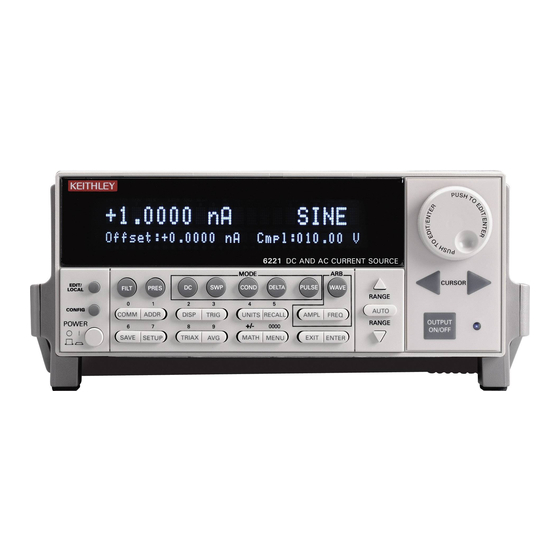
Page 21: Figure 1-1 Models 6220 And 6621 Front Panels
Model 6220/6221 User’s Manual Getting Started Figure 1-1 Models 6220 and 6621 front panels Model 6220: 6220 POWER Model 6221: 6221 POWER Return to Section 1 topics... - Page 22 Getting Started Model 6220/6221 User’s Manual 1 Special keys and power switch: EDIT/LOCAL Dual function – While in local, EDIT selects the source editing mode. While in remote, LOCAL cancel the remote mode. CONFIG Use to configure a function or operation. POWER Power switch –...
- Page 23 Model 6220/6221 User’s Manual Getting Started Bottom Row SAVE Saves up to five instrument setups for future recall, and selects power-on setup. SETUP Restores a default setup (preset or *RST) or a user saved setup. TRIAX Configures triax connector: Inner shield and Output Low. Can also press CONFIG >...
-
Page 24: Rear Panel Summaries
Getting Started Model 6220/6221 User’s Manual Rear panel summaries The rear panel of the Models 622x is shown in Figure 1-2. The Model 6221 rear panel is shown, but the Model 6220 is identical except it does not have the Ether- net connector. -
Page 25: Heat Sink And Cooling Vents
Model 6220/6221 User’s Manual Getting Started 4 DIGITAL I/O Male DB-9 connector. Four pins for digital output, one pin for Start of Test (SOT) trigger, and one for external voltage (VEXT) input. 5 RS-232 Female DB-9 connector: • For RS-232 operation, use a straight-through (not null modem) DB-9 shielded cable for connection to the PC. - Page 26 1-10 Getting Started Model 6220/6221 User’s Manual WARNING When handling the Model 622x, NEVER touch the heat sink located on the right side of the case. This heat sink could be hot enough to cause burns. CAUTION NEVER place a container of liquid (e.g., water, coffee, etc.) on the top cover.
-
Page 27: Power-Up
Model 6220/6221 User’s Manual Getting Started 1-11 • Rack mounting high power dissipation equipment adjacent to the Model 622x could cause excessive heating to occur. The specified ambient temperature must be maintained around the surfaces of the Model 622x to specified accura- cies. -
Page 28: Source Preset
1-12 Getting Started Model 6220/6221 User’s Manual WARNING The power cord supplied with the Model 622x contains a sepa- rate ground wire for use with grounded outlets. When proper connections are made, instrument chassis is connected to power line ground through the ground wire in the power cord. Failure to use a grounded outlet may result in personal injury or death due to electric shock. -
Page 29: Menus
Model 6220/6221 User’s Manual Getting Started 1-13 Menus Many aspects of operation are configured through menus. A direct access menu can be opened by pressing a single key, and other menus require that the CONGIF key be pressed before pressing another key. CONFIG menus NOTE “Press CONFIG >... -
Page 30: Editing Controls
1-14 Getting Started Model 6220/6221 User’s Manual Model 6221: AMPL opens menu to set AMPL: (value) (Section FREQ opens menu to set FREQ (frequency) (Section MAIN menu The MAIN MENU is a direct access menu that is opened by pressing the MENU key. - Page 31 Model 6220/6221 User’s Manual Getting Started 1-15 Model 6220 menu navigation After entering a menu structure, use the editing keys as follows: Selecting menu items Use the Cursor Keys to place the blinking cursor on a menu item to be opened or selected.
-
Page 32: Password
1-16 Getting Started Model 6220/6221 User’s Manual Model 6221 menu navigation Editing for the Model 6221 is basically the same as editing for the Model 6220, except for the following differences: • Cursor control is provided by the Cursor Keys located under the rotary knob. -
Page 33: Remote Interface
Model 6220/6221 User’s Manual Getting Started 1-17 Remote interface For remote operation, one of the following interfaces can be used: GPIB, RS-232, and (for the Model 6221) Ethernet. When using the GPIB, the SCPI or KI-220 lan- uage can be used. NOTE Interface selection and configuration can be performed from the COMMUNICATIONS SETUP menu, which is ac- cessed by pressing the COMM key. -
Page 34: Default Settings
1-18 Getting Started Model 6220/6221 User’s Manual Default settings The Model 622x can be restored to one of seven setup configurations: five user- saved setups, PRESET (bench defaults), and *RST (bus defaults). As shipped from the factory, the Model 622x powers up to the PRESET settings. PRESET settings provide a general purpose setup for front panel operation, while the *RST settings do the same for remote operation. -
Page 35: Select Power-On Setup
Model 6220/6221 User’s Manual Getting Started 1-19 Select power-on setup Power-on to PRESET defaults: Press SETUP > Select POWER ON > Select PRESET Power-on to *RST defaults: Press SETUP > Select POWER ON > Select *RST Power-on to user setup: Press SETUP >... - Page 36 1-20 Getting Started Model 6220/6221 User’s Manual Return to Section 1 topics...
-
Page 37: Output Connections
Output Connections Section 2 topics Output connectors, page 2-2 Triax connector, page 2-2 Ground points, page 2-3 LO and GUARD banana jacks, page 2-3 INTERLOCK, page 2-4 Output configurations, page 2-5 Triax inner shield, page 2-6 Triax output low, page 2-7 Guards, page 2-8 Triax Cable Guard, page 2-8... -
Page 38: Output Connectors
Output Connections Model 6220/6221 User’s Manual Output connectors Triax connector Current source output is accessed at the 3-lug female triax connector on the rear panel. Use a 3-slot male triax cable to make connections to this connector. A triax cable terminated with alligator clips (Model 237-ALG-2) is a supplied item for the Model 622x (see “Supplied triax cable”... -
Page 39: Ground Points
Model 6220/6221 User’s Manual Output Connections shield connection setting. See “Triax Cable Guard” on page 2-8 for details on using the Cable Guard. Outer shield – The outer shield of the triax connector is always connected to Earth Ground of the Model 622x (see “Ground points”... -
Page 40: Interlock
Output Connections Model 6220/6221 User’s Manual GUARD banana jack The GUARD available at the banana jack is different from CABLE GUARD that can be accessed at the triax cable. See “Guards” on page 2-8 for more informa- tion. INTERLOCK The Model 622x is equipped with an INTERLOCK that is to be connected to an interlock switch (see Figure 2-3). -
Page 41: Output Configurations
Figure 2-5B). Using the Model 622x with the triax inner shield connected to Output Low makes it compatible with the Keithley Model 220 current source. WARNING To prevent electric shock and/or damage to the Model 622x, DO NOT exceed the maximum (Max) voltage levels indicated in... -
Page 42: Triax Inner Shield
Triax inner shield The inner shield of the triax connector can be connected to Output Low (to be compatible with the Keithley 220 Current Source) or to Cable Guard. Output Low is the default connection. The current source OUTPUT must be OFF in order to change the inner shield set- ting. -
Page 43: Triax Output Low
Model 6220/6221 User’s Manual Output Connections Commands for triax inner shield connection: ‘ Query connection for triax inner shield. OUTPut:ISHield? ‘ Connect inner shield to Cable Guard or Output Low. OUTPut:ISHield <name> <name> = GUARd or OLOW ‘ Example – Turns off the current source OUTPUT and connects the inner shield of the OUTPUT connector to Cable Guard: OUTPut OFF OUTPut:ISHield GUARd... -
Page 44: Guards
Output Connections Model 6220/6221 User’s Manual Guards The Model 622x provides two guards: triax Cable Guard and banana jack Guard. Cable Guard – This guard provides a voltage that is at essentially the same potential as Output High of the Model 622x. Guarding may greatly reduce leakage current and capacitance in the test circuit. -
Page 45: Floating The Current Source
These capacitances, which cannot be guarded out, may negate the need for Cable Guard (especially for low- impedance DUT). The Keithley Model 2182/2182A Nanovoltmeter has relatively high input capacitance (~300pF, and ~500pF in special mode only). -
Page 46: Basic Connections
2-10 Output Connections Model 6220/6221 User’s Manual Basic connections Basic connections can be used for low voltage (not greater than 30Vrms, 42Vpeak) testing where guarding and/or noise shielding are not required. Basic connections to a DUT are shown in Figure 2-6. -
Page 47: Figure 2-7 Noise Shield
Model 6220/6221 User’s Manual Output Connections 2-11 Figure 2-7 Noise shield A) Inner shield connected to Output Low B) Inner shield connected to Cable Guard, Output Low connected to earth ground Safety shield connections A safety shield must be used whenever hazardous voltages (>30Vrms, 42Vpeak) will be present. -
Page 48: Figure 2-9 Cable Guard Connections – Triax Inner Shield Connected To Cable Guard
2-12 Output Connections Model 6220/6221 User’s Manual Figure 2-9 Cable Guard connections – triax inner shield connected to Cable Guard A safety shield must be used whenever hazardous voltages (>30Vrms, 42Vpeak) will be present in the test circuit. Figure 2-10 shows how to make guarded connec- tions with the use of a safety shield. -
Page 49: Using A Test Fixture
Model 6220/6221 User’s Manual Output Connections 2-13 Using a test fixture In order to faciliate safe operation and optimum performance, a safety test fixture with a built-in interlock switch must be used. The interlock switch of the test fixture is to be connected to the “INTERLOCK” of the Model 622x (see page 2-4). NOTE Guidelines to build a safe, high performance test fixture are provided in Section 2 of the Reference Manual (see “Using a test fixture”). - Page 50 DC Current Source Operation Section 3 topics Current source output capabilities, page 3-2 Source ranges, page 3-2 Compliance, page 3-3 Output power (source or sink), page 3-3 Output response, page 3-5 Setting source and compliance, page 3-8 Source and compliance editing, page 3-8 Sourcing current, page 3-12...
-
Page 51: Dc Current Source Operation
DC Current Source Operation Model 6220/6221 User’s Manual Current source output capabilities • Nine ranges to source current from 100fA to 105mA. • Compliance can be set from 0.1V to 105V in 10mV steps. • Maximum output power is 11W. •... -
Page 52: Compliance
Model 6220/6221 User’s Manual DC Current Source Operation Compliance The compliance setting limits the output voltage of the Model 622x. The voltage compliance limit can be set from 0.1V to 105V in 10mV steps. The output will not exceed the programmed compliance level. Make sure to set compliance to a voltage level that is greater than the voltage requirements for the load. - Page 53 DC Current Source Operation Model 6220/6221 User’s Manual When operating as a sink, the Model 622x is dissipating power rather than sourc- ing it. The polarity of the current and voltage seen at the output is opposite (one positive, one negative). An external source or an energy storage device, such as a capacitor, can force operation into the sink region.
-
Page 54: Output Response
Model 6220/6221 User’s Manual DC Current Source Operation Figure 3-2 Output boundaries (source and sink) Output response Output response is the time it takes for an output change to settle to within 1% of its final value. For the Model 6220, output response (settling time) can be as fast as 100µs (typical). - Page 55 DC Current Source Operation Model 6220/6221 User’s Manual For example, assume the Model 6221 is on the 2mA range and FAST response is selected. For this configuration, the Settling Time is specified at 2µs (typical). Also assume the load impedance is 1kΩ. With the analog filter enabled, the additional settling time (five time constants) is calculated as follows: Additional settling time = 5RC = 5 x 1kΩ...
- Page 56 Model 6220/6221 User’s Manual DC Current Source Operation Response speed setting (6221 only) The filter response speed of the Model 6221 can be set for FAST or SLOW. For the SLOW setting, the output response of the Model 6221 is the same as the out- put response of the Model 6220.
-
Page 57: Setting Source And Compliance
DC Current Source Operation Model 6220/6221 User’s Manual Setting source and compliance Source and compliance editing from the front panel cannot be performed from the front panel if the Model 622x is in remote. To return to the local state, press the LOCAL key. - Page 58 Model 6220/6221 User’s Manual DC Current Source Operation Source/compliance editing notes The following notes apply to source editing for both the Models 6220 (Figure 3-3) and 6221 (Figure 3-4): The displayed source and/or compliance value can only be edited if the DC source mode is selected.
- Page 59 3-10 DC Current Source Operation Model 6220/6221 User’s Manual Figure 3-4 Source and compliance editing – Model 6221 Rotary Knob & Cursor Keys Range Keys DC Output Select Key EDIT key Numeric Entry Keys 0 1 2 3 4 5 6 7 8 9 +/– 0000 ENTER / EXIT Keys EXIT ENTER...
-
Page 60: Autorange
Model 6220/6221 User’s Manual DC Current Source Operation 3-11 Autorange Front panel operation The AUTO range key is a single action control to select the best fixed range for the displayed source value. After setting a source value, pressing AUTO will ensure that the best fixed range is selected. -
Page 61: Source Preset
3-12 DC Current Source Operation Model 6220/6221 User’s Manual Source preset The PRES key can be used to set the source to a preset value and range. When the PRES key is pressed, the source will select the preset range and set the pre- set value. - Page 62 Model 6220/6221 User’s Manual DC Current Source Operation 3-13 Remote programming – Autorange can be used when setting the I-source value. With autorange enabled, the Model 622x will automatically select the optimum (lowest) range to accommodate the source value. The commands to select the source range, and set the output and compliance values are provided in Table 3-2.
- Page 63 3-14 DC Current Source Operation Model 6220/6221 User’s Manual Example – Enables the analog filter and, for the Model 6221, sets the output response to fast: ‘ Enables the analog filter. CURRent:FILTer ON ‘ Sets the output response of the 6221 to FAST. OUTPut:RESPonse FAST Turn on the output.
-
Page 64: Remote Programming - Source Output Commands
Model 6220/6221 User’s Manual DC Current Source Operation 3-15 Remote programming – source output commands Table 3-2 lists the commands to configure and control the DC output. A program- ming example to output DC current is also provided. Table 3-2 DC output commands Command Description... -
Page 65: Applications
Resistivity measurements – Certain semiconductor materials such as sili- con have high resistivities. The Model 622x can be used to source stable and accurate current, and the Keithley 6514 Electrometer can be used to provide an accurate voltage measurement. Resistivity is then calculated. - Page 66 Sweeps Section 4 topics Sweep overview, page 4-2 Linear staircase sweep, page 4-2 Logarithmic staircase sweep, page 4-2 Custom sweep, page 4-2 Sweep characteristics, page 4-4 Custom sweep editing, page 4-4 Using auto-copy with custom sweeps, page 4-4 Source ranging, page 4-4 Sweep delay, page 4-5 Front panel sweep operation, page 4-5 Using the sweep configuration menu, page 4-5...
-
Page 67: Sweeps
Sweeps Model 6220/6221 User’s Manual Sweep overview As shown in Figure 4-1, the Model 622x Current Source can generate three types of DC current sweeps. NOTE User setups cannot be saved or recalled while a sweep is armed or running. Attempting to do so will generate error +413 Not allowed with mode arm. -
Page 68: Logarithmic Staircase Sweep
Model 6220/6221 User’s Manual Sweeps Figure 4-1 Comparison of sweep types A. Linear Staircase Sweep B. Logarithmic Staircase Sweep C. Custom Sweep Return to Section 4 topics... -
Page 69: Sweep Characteristics
Sweeps Model 6220/6221 User’s Manual Sweep characteristics NOTE Jitter – Step-to-step sweep timing may jitter as much as 1ms. This jitter can be eliminated by disabling the front panel. For details, see “Step-to-step timing jitter” on page 1-12. Custom sweep editing A typical custom sweep editing display is shown below: P12345: +1.234567 mA Del:123456.789s Cmpl:100.00 V... -
Page 70: Sweep Delay
Model 6220/6221 User’s Manual Sweeps Sweep delay The sweep delay parameter determines how long the Model 622x will remain on each sweep step once the output current is set to the step value. For linear and logarithmic staircase sweeps, the sweep delay period is the same for every step in the sweep. -
Page 71: Performing A Staircase Sweep
Sweeps Model 6220/6221 User’s Manual Performing a staircase sweep Configure source functions: If desired, set the bias current (output current prior to the start of the sweep) by pressing the DC key and then setting the current to the desired value. Select the compliance display field, then set the voltage compliance as appropriate for expected sweep parameters. -
Page 72: Performing A Custom Sweep
Model 6220/6221 User’s Manual Sweeps Performing a custom sweep Configure the bias current (output current prior to the start of the sweep) by pressing the DC key and then setting the current to the desired value. Configure the sweep as follows: Press CONFIG then SWP to enter the sweep configuration menu. -
Page 73: Remote Sweep Operation
Sweeps Model 6220/6221 User’s Manual Remote sweep operation Procedures for programming and running a sweep are shown on the following pages. Each of these procedures includes commands for a typical sweep exam- ple. Table 4-2 summarizes parameters for each of these examples. See “SCPI commands —... -
Page 74: Running A Staircase Sweep
Model 6220/6221 User’s Manual Sweeps Running a staircase sweep Configure source functions. Examples – The following commands restore defaults, set the bias current to 100μA, and the compliance to 10V: ‘ Restore 622x defaults. *RST ‘ Set bias current to 100μA SOUR:CURR 1e-4 ‘... -
Page 75: Running A Custom Sweep
4-10 Sweeps Model 6220/6221 User’s Manual Running a custom sweep Configure source functions. Examples – The following commands restore defaults and set the bias current to 50μA: ‘ Restore 622x defaults. *RST ‘ Set bias current to 50μA SOUR:CURR 5e-5 Configure the sweep. -
Page 76: Scpi Commands - Sweeps
Model 6220/6221 User’s Manual Sweeps 4-11 SCPI commands — sweeps Commands for linear and logarithmic staircase sweeps are listed in Table 4-3, while commands for custom (list) sweeps are listed in Table 4-4. Table 4-3 Staircase sweep commands (linear and logarithmic) Command Description Default... -
Page 77: Table 4-4 Custom (List) Sweep Commands
4-12 Sweeps Model 6220/6221 User’s Manual Table 4-4 Custom (list) sweep commands Command Description Defines list of currents. SOURce[1]:LIST:CURRent <NRf> <NRf> = -0.105 to 0.105 (A) [,<NRf>, ...<NRf>] Adds current points to existing list. SOURce[1]:LIST:CURRent:APPend <NRf> <NRf> = -0.105 to 0.105 (A) [,<NRf>, ...<NRf>] Defines list of delay values. -
Page 78: Delta, Pulse Delta, And Differential Conductance
5-2 Delta, page 5-13 Model 622x measurement process, page 5-13 Test systems, page 5-4 Configuration settings, page 5-15 Keithley instrumentation requirements, page 5-4 Operation, page 5-16 System configurations, page 5-4 Setup and arm commands, page 5-19 System connections,... -
Page 79: Operation Overview
Delta, Pulse Delta, and Differential Conductance Model 6220/6221 User’s Manual Operation overview The Model 6220 or 6221 Current Source can be used with a Model 2182/2182A Nanovoltmeter to perform Delta and Differential Conductance. The Model 6221/2182A combination can also perform Pulse Delta. These operations use a delta current-reversal technique to cancel the effects of thermal EMFs. -
Page 80: Figure 5-1 Delta, Pulse Delta, And Differential Conductance Measurements
Model 6220/6221 User’s Manual Delta, Pulse Delta, and Differential Conductance Figure 5-1 Delta, Pulse Delta, and Differential Conductance measurements A) Delta measurements DELTA DELTA Reading Reading DELTA DELTA Reading Reading B) Pulse Delta measurements Pulse Delta Pulse Delta Pulse Delta Reading Reading Reading... -
Page 81: Test Systems
For details, see “Using the example software” in Section 10 of the Reference Manual. Keithley instrumentation requirements Keithley instrumentation requirements for Delta, Pulse Delta, and Differential Con- ductance are: • Models 6220 and 2182 – Delta and Differential Conductance •... -
Page 82: System Connections
Model 6220/6221 User’s Manual Delta, Pulse Delta, and Differential Conductance Serial communications In order to perform Delta, Pulse Delta, or Differential Conductance measure- ments, the Model 622x must communicate to the Model 2182/2182A over the serial (RS-232) interface. With serial communications properly configured and connected, the Model 622x will automatically send setup commands to the Model 2182/2182A when Delta, Pulse Delta, or Differential Conductance is armed. -
Page 83: Figure 5-3 System Connections – Stand-Alone Operation
Delta, Pulse Delta, and Differential Conductance Model 6220/6221 User’s Manual Trigger Link – The Trigger Link synchronizes triggering between the Current Source and the Nanovoltmeter. Trigger Link connections assume that the Model 2182/2182A is using the factory default (hard-wired) configuration: EXT TRIG (input) = line #2 VMC (output) = line #1) Delta, Pulse Delta, and Differential Conductance will not work if the... -
Page 84: Figure 5-4 System Connections – Pc Control Of Model 622X
Model 6220/6221 User’s Manual Delta, Pulse Delta, and Differential Conductance Figure 5-4 System connections – PC control of Model 622x Return to Section 5 topics... -
Page 85: Dut Test Connections
Delta, Pulse Delta, and Differential Conductance Model 6220/6221 User’s Manual DUT test connections WARNING Before making or breaking test connections, the Models 622x and 2182/2182A must be turned off and the line cords must be disconnected from AC line power. DUT test connections are shown in Figure 5-5. -
Page 86: Configuring Communications
Model 6220/6221 User’s Manual Delta, Pulse Delta, and Differential Conductance Configuring communications For both front panel and remote operation, the RS-232 of the Model 2182/2182A must be enabled (on), and the selected communications interface for the Model 622x must be the GPIB or the Ethernet (Model 6221 only). Model 2182/2182A communications Configure the Model 2182/2182A for RS-232 communications as follows: On the Model 2182/2182A, press the SHIFT key and then the RS-232 key to... -
Page 87: Triggering Sequence
5-10 Delta, Pulse Delta, and Differential Conductance Model 6220/6221 User’s Manual Arming and Starting the Test Arming – After a delta test is configured, the test is armed by pressing the DELTA key, PULSE key (Pulse Delta), or COND key (Differential Conductance). For remote programming, the following commands are used to arm the test: SOUR:DELT:ARM ‘... -
Page 88: Readings
Model 6220/6221 User’s Manual Delta, Pulse Delta, and Differential Conductance 5-11 Readings Display readings Display reading examples: +1.23456 nV Delta Delta voltage reading +1.23456 Ω Delta Delta ohms reading +1.23456 S D Cond Differential Conductance Siemens reading 1, 2, 3 +1.23456 mWp Pulse Pulse Delta peak power (Watts) reading 1, 2, 3... -
Page 89: Table 5-1 Measurement Unit Commands
5-12 Delta, Pulse Delta, and Differential Conductance Model 6220/6221 User’s Manual The default units for the Model 622x is volts. With Ohms (Ω) units or Siemens (S) units selected, a reading is calculated as follows: Ω = V/I S = I/V Where: V is the Delta, Pulse Delta, or Differential Conductance voltage reading. -
Page 90: Read Commands
Model 6220/6221 User’s Manual Delta, Pulse Delta, and Differential Conductance 5-13 Read commands The Model 622x does not perform measurements. However, raw readings are sent from the Model 2182/2182A to the Model 622x to calculate Delta, Pulse Delta, or Differential Conductance readings. Readings from the Model 2182/ 2182A are processed, stored, and displayed by the Model 622x. -
Page 91: Figure 5-6 Delta Measurement Technique
5-14 Delta, Pulse Delta, and Differential Conductance Model 6220/6221 User’s Manual Figure 5-6 Delta measurement technique DELTA DELTA Reading Reading DELTA DELTA Reading Reading · 1st Delta Reading · 3rd Delta Reading · · 4th Delta Reading 2nd Delta Reading The following equation can be used to calculate any Delta reading: ⎛... -
Page 92: Configuration Settings
Model 6220/6221 User’s Manual Delta, Pulse Delta, and Differential Conductance 5-15 Measurement units The fundamental measurement for Delta is voltage (Volts; V). However, the volt- age reading can converted into a conductance (Siemens; S), resistance (Ohms; Ω), or power (Watts; W) reading. See page 5-11 for details on selecting... -
Page 93: Operation
5-16 Delta, Pulse Delta, and Differential Conductance Model 6220/6221 User’s Manual Operation Delta operation – front panel The system configuration for front panel stand-alone operation is shown in Figure 5-2A on page 5-5. Connections are shown in the following illustrations. All power must be removed from all components in the system before making connections: •... - Page 94 Model 6220/6221 User’s Manual Delta, Pulse Delta, and Differential Conductance 5-17 When finished, press EXIT to disarm Delta. On the Model 622x, press RECALL to access the Delta readings stored in the buffer. Operation – PC control The system configuration for PC control of the Model 622x is shown in Figure 5-2B.
- Page 95 5-18 Delta, Pulse Delta, and Differential Conductance Model 6220/6221 User’s Manual Examples – The following commands demonstrate proper syntax for sending commands and returning responses to queries over the serial port: ‘ Select 2V range for 2182/ SYST:COMM:SER:SEND “VOLT:RANG 2” 2182A.
-
Page 96: Setup And Arm Commands
Model 6220/6221 User’s Manual Delta, Pulse Delta, and Differential Conductance 5-19 Read Delta readings – While Delta is running, the latest Model 2182/2182A Delta reading can be read by the Model 622x using the following command: ‘ Reads the latest Delta reading. SENS:DATA? The above read command reads the last Delta reading that was performed by the Model 2182/2182A. -
Page 97: Table 5-2 Delta Commands
5-20 Delta, Pulse Delta, and Differential Conductance Model 6220/6221 User’s Manual Table 5-2 Delta commands Command Description Default [SOURce[1]]:DELTa:NVPResent? Queries connection to 2182A. 1 = yes, 0 = no [SOURce[1]]:DELTa:HIGH <NRf> Sets high source value (amps). 1e-3 <NRf> = 0 to 105e-3 Sets low source value (amps). -
Page 98: Pulse Delta
Model 6220/6221 User’s Manual Delta, Pulse Delta, and Differential Conductance 5-21 Pulse Delta Use the Keithley Model 2182A with the Model 6221 to run Pulse Delta. Model 6221 measurement process Pulse Delta measurements For Pulse Delta, the Model 6221 outputs current pulses. Current pulses that have a short pulse width are ideal to test a low-power DUT that is heat sensitive. -
Page 99: Pulse Delta Outputs
5-22 Delta, Pulse Delta, and Differential Conductance Model 6220/6221 User’s Manual Where: Y is the measurement at the high pulse. X is the measurement at the first low pulse. Measurement units The fundamental Pulse Delta measurement explained above is in volts. The read- ing can instead be converted into Ohms (W), Siemens (S), or Power (W). - Page 100 Model 6220/6221 User’s Manual Delta, Pulse Delta, and Differential Conductance 5-23 Like the Fixed output shown in Figure 5-8, a Sweep output is synchronized to the frequency of the power line voltage, and the pulse width is adjustable and is the same for all pulses.
-
Page 101: Figure 5-8 Pulse Timing
5-24 Delta, Pulse Delta, and Differential Conductance Model 6220/6221 User’s Manual Figure 5-8 Pulse timing Return to Section 5 topics... -
Page 102: Figure 5-9 Pulse Sweep Output Examples
Model 6220/6221 User’s Manual Delta, Pulse Delta, and Differential Conductance 5-25 Figure 5-9 Pulse sweep output examples A) Staircase sweep pulse train: 2 to 10mA in 2mA steps B) Logarithmic sweep pulse train: 1 to 10mA using 5 logarithmic C) Custom sweep pulse train: 1mA, 2mA, 4mA, 8mA, and 16mA (5 points) Return to Section 5 topics... -
Page 103: Configuration Settings
5-26 Delta, Pulse Delta, and Differential Conductance Model 6220/6221 User’s Manual Duty Cycle Duty cycle defines the ratio between pulse “on” time and pulse “off” time during a Pulse Delta cycle. For example, for a 25% duty cycle, the pulse would be “on” (high) for one-quarter of the cycle, and “off”... - Page 104 Model 6220/6221 User’s Manual Delta, Pulse Delta, and Differential Conductance 5-27 Fixed output settings The following parameters are set from the CONFIG PULSE DELTA menu that is accessed by pressing the CONFIG key and then the PULSE key. I-Hi and I-Lo These settings specify the high and low level of the pulses.
- Page 105 5-28 Delta, Pulse Delta, and Differential Conductance Model 6220/6221 User’s Manual Interval The Pulse Delta cycle time period (interval) is expressed as a number of power line cycles (PLC). For 60Hz one PLC is 16.667ms, and for 50Hz, one PLC is 20ms.
-
Page 106: Operation
Model 6220/6221 User’s Manual Delta, Pulse Delta, and Differential Conductance 5-29 Operation Pulse Delta operation – front panel The system configuration for front panel stand-alone operation is shown in Figure 5-2A on page 5-5. Connections are shown in the following illustrations. All power must be removed from all components in the system before making connections: •... - Page 107 5-30 Delta, Pulse Delta, and Differential Conductance Model 6220/6221 User’s Manual To set the measurement units, press the UNITS key to display the READING UNITS menu. Select VOLTS, OHMS, WATTS, or SIEMENS. When WATTS is selected, you will then be prompted to select the power units type: AVERAGE or PEAK.
- Page 108 Model 6220/6221 User’s Manual Delta, Pulse Delta, and Differential Conductance 5-31 The following query command is used to return the response to a query command sent over the serial port: SYSTem:COMMunicate:SERial:ENTer? When communicating over the serial port, there are no errors reported if a Model 2182A is not connected to the serial port.
-
Page 109: Setup Commands
5-32 Delta, Pulse Delta, and Differential Conductance Model 6220/6221 User’s Manual The initiate command starts Pulse Delta readings. After the specified finite number of Pulse Delta readings are performed, Pulse Delta will stop running. At this point another initiate command will re-start Pulse Delta. -
Page 110: Table 5-3 Pulse Delta Commands
Model 6220/6221 User’s Manual Delta, Pulse Delta, and Differential Conductance 5-33 Table 5-3 Pulse Delta commands Command Description Default Queries if 2182A is connected. SOURce[1]:PDELta:NVPResent? 1 = yes, 0 = no Sets high pulse value (amps). 1e-3 SOURce[1]:PDELta:HIGH <NRf> <NRf> = -105e-3 to 105e-3 Sets low pulse value (amps). -
Page 111: Differential Conductance
5-34 Delta, Pulse Delta, and Differential Conductance Model 6220/6221 User’s Manual 3. When using a Fixed output, use the SOUR:PDEL:INT command to set the Pulse Delta cycle time period (in PLCs). When using Sweep output, use the SOUR:DEL command to set the Pulse Delta cycle time period (in seconds) for a linear or log sweep. - Page 112 Model 6220/6221 User’s Manual Delta, Pulse Delta, and Differential Conductance 5-35 also calculate, display, and store the differential conductance (dG) or differential resistance (dR) for each calculated point. Return to Section 5 topics...
-
Page 113: Figure 5-10 Differential Conductance Measurement Process
5-36 Delta, Pulse Delta, and Differential Conductance Model 6220/6221 User’s Manual Figure 5-10 Differential Conductance measurement process dV Calc dV Calc dV Calc dV Calc dV Calc dV Calc dV Calculations · · · · · · dG and dR Calculations Return to Section 5 topics... - Page 114 Model 6220/6221 User’s Manual Delta, Pulse Delta, and Differential Conductance 5-37 Differential Conductance calculations dV calculations While the dV calculations for the first six dV readings are shown in Figure 5-10, the following formula can be used to calculate any dV reading in the test: –...
-
Page 115: Configuration Settings
5-38 Delta, Pulse Delta, and Differential Conductance Model 6220/6221 User’s Manual Measurement units The fundamental measurement for Differential Conductance is differential voltage (dV). However, the dV reading can be converted into a differential conductance (dG), differential resistance (dR), or power (Watts) reading. See page 5-11 details on selecting “Measurement... -
Page 116: Operation
Model 6220/6221 User’s Manual Delta, Pulse Delta, and Differential Conductance 5-39 Delay – The delay for Differential Conductance is used to allow the current source to settle when the output changes to the next stepped delta level. This delay occurs after a trigger from the Model 2182/2182A is received. Delay can be set from 1ms to 9999.999s. - Page 117 5-40 Delta, Pulse Delta, and Differential Conductance Model 6220/6221 User’s Manual To set the measurement units, press the UNITS key to display the READING UNITS menu. Select VOLTS, OHMS, WATTS, or SIEMENS. Measurement units can be changed while Differential Conductance is running.
- Page 118 Model 6220/6221 User’s Manual Delta, Pulse Delta, and Differential Conductance 5-41 The following query command is used to return the response to a query command sent over the serial port: SYSTem:COMMunicate:SERial:ENTer? When communicating over the serial port, there are no errors reported if a Model 2182/2182A is not connected to the serial port.
-
Page 119: Setup And Arm Commands
5-42 Delta, Pulse Delta, and Differential Conductance Model 6220/6221 User’s Manual Trace points specifies the size of the buffer. Buffer size should be the same value as the number of Differential Conductance readings in the test. See Section 6 for details on all buffer commands. The initiate command starts Differential Conductance readings. -
Page 120: Table 5-4 Differential Conductance Commands
Model 6220/6221 User’s Manual Delta, Pulse Delta, and Differential Conductance 5-43 Table 5-4 Differential Conductance commands Command Description Default Queries if 2182/2182A is con- SOURce[1]:DCONductance:NVPResent? nected. 1 = yes, 0 = no SOURce[1]:DCONductance:STARt <NRf> Sets start value (amps). -10e-6 <NRf> = -105e-3 to 105e-3 Sets step size (amps). - Page 121 5-44 Delta, Pulse Delta, and Differential Conductance Model 6220/6221 User’s Manual The query form for the arm command (SOUR:DCON:ARM?) is used deter- mine if Differential Conductance is armed. A returned “1” indicates that Differ- ential Conductance is armed. A “0” indicates that Differential Conductance is not armed.
-
Page 122: Averaging Filter, Math, And Buffer
Averaging Filter, Math, and Buffer Section 6 topics Averaging filter, page 6-2 Averaging filter characteristics, page 6-2 Filter setup and control, page 6-4 Remote programming – Averaging filter, page 6-4 Math, page 6-7 mX+b and m/X+b (reciprocal), page 6-5 Configuring mX+b and m/X+b, page 6-6 Remote programming –... -
Page 123: Averaging Filter
Averaging Filter, Math, and Buffer Model 6220/6221 User’s Manual Averaging filter The average filter can be used with Delta, Pulse Delta, and Differential Conduc- tance. There are two types of averaging filter: moving and repeating. “Filter type” is explained on page 6-3. - Page 124 Model 6220/6221 User’s Manual Averaging Filter, Math, and Buffer Filter type There are two averaging filter types: moving and repeating. Moving filter Basic moving filter operation – For the moving filter, every delta reading yields a filtered delta reading. Every time a delta reading is placed in the buffer stack, the readings in the stack are averaged to yield a single filtered reading.
-
Page 125: Filter Setup And Control
Averaging Filter, Math, and Buffer Model 6220/6221 User’s Manual Filter window The averaging filter uses a “noise” window to control filter threshold. As long as the signal remains within the selected window, A/D conversions continue to be placed in the stack. If the signal changes to a value outside the window, the filter resets, and the filtering process starts over. -
Page 126: Math
Model 6220/6221 User’s Manual Averaging Filter, Math, and Buffer Table 6-2 Averaging filter commands Command Description Default SENSe[1]:AVERage:TCONtrol <name> Select filter control. <name> = MOVing or REPeat. SENSe[1]:AVERage:WINDow <NRf> Set filter window as % of range: <NRf> = 0 to 10 (0 selects no window) SENSe[1]:AVERage:COUNt <NRf>... -
Page 127: Configuring Mx+B And M/X+B
Averaging Filter, Math, and Buffer Model 6220/6221 User’s Manual Configuring mX+b and m/X+b To select and configure mX+b and m/X+b from the front panel, press CONFIG then MATH. Select the math function (MX+B or M/X+B), then enter the required parameters (m and b). Once a math function is selected, press the MATH key to toggle math on or off. -
Page 128: Buffer
Model 6220/6221 User’s Manual Averaging Filter, Math, and Buffer Buffer The Model 622x has a buffer (data store) to store readings and related data ele- ments for one to 65,536 buffer readings. Buffer readings are readings from the Model 2182/2182A that were processed by the Model 622x as delta readings (Delta, Pulse Delta, or Differential Conductance). -
Page 129: Storing Readings
Averaging Filter, Math, and Buffer Model 6220/6221 User’s Manual Buffer statistics The following statistics are available on the stored buffer readings: • MIN and MAX provides the minimum and maximum readings stored in the buffer. It also indicates the buffer location of these readings. •... -
Page 130: Figure 6-1 Buffer Recall
Model 6220/6221 User’s Manual Averaging Filter, Math, and Buffer Buffer statistics – While in buffer RECALL, use the EDIT/LOCAL key (see Figure 6-1). Each press of this key displays the next statistic. After the last statistic is displayed (Std Dev), pressing EDIT/LOCAL will display the stored readings. When finished, press EXIT to return to the normal display. - Page 131 6-10 Averaging Filter, Math, and Buffer Model 6220/6221 User’s Manual Return to Section 6 topics...
-
Page 132: Wave Functions (6221 Only)
Wave Functions (6221 Only) Section 7 topics Wave function overview, page 7-2 Front panel wave function operation, page 7-8 Setting waveform parameters, page 7-3 Using the wave function menu, page 7-8 Editing parameters, page 7-3 Generating a sine wave, page 7-10 Amplitude and offset editing, page 7-3 Generating an arbitrary waveform, page 7-11 Amplitude and units, page 7-3... -
Page 133: Wave Function Overview
Wave Functions (6221 Only) Model 6220/6221 User’s Manual Wave function overview Table 7-1 summarizes the basic characteristics of the four wave functions avail- able in the Model 6221. More details on various aspects can be found in the fol- lowing paragraphs. Table 7-1 Wave function characteristics Wave function... -
Page 134: Setting Waveform Parameters
Model 6220/6221 User’s Manual Wave Functions (6221 Only) Setting waveform parameters NOTE User setups cannot be saved or recalled while Wave is armed or running. Attempting to do so will generate error +413 Not allowed with mode arm. Editing parameters The AMPL and FREQ keys also function as left arrow and right arrow keys, respectively, when editing a numeric value or scrolling through a menu. -
Page 135: Frequency
Wave Functions (6221 Only) Model 6220/6221 User’s Manual Arbitrary waveform ranging The arbitrary waveform is described in normalized units from -1 to +1. See the fol- lowing example: Ranging: BEST Amplitude: 10mA peak Offset: 0mA ARB values: range from +1 to -1 These settings will generate a waveform with a peak-to-peak value of 20mA on the 20mA range. -
Page 136: Duty Cycle
Model 6220/6221 User’s Manual Wave Functions (6221 Only) Duty cycle For a square wave Figure 7-2A, the duty cycle setting is the portion of the total cycle that the wave is high relative to the period of the waveform. For a ramp waveform Figure 7-2B, the duty cycle corresponds to the fraction of the total wave... -
Page 137: Phase Marker
Wave Functions (6221 Only) Model 6220/6221 User’s Manual Phase marker The phase marker (Figure 7-3) allows you to set a pulse marker that defines a specific point of a waveform over a range of 0 to 360°. The phase marker signal is a 1μs pulse that appears on the selected line of the external trigger connector (see information on the external trigger connector in Section 8 of the Model 622x Reference Manual for connector designations). -
Page 138: Duration
Model 6220/6221 User’s Manual Wave Functions (6221 Only) Duration The duration setting defines how long the waveform is generated. You can set the duration in time over a range of 100ns to 999999.999s, in cycles from 0.001 to 99999999900 cycles (provided the equivalent time, cycles/frequency does not exceed the upper time duration limit), or choose a continuous waveform (INFinite setting). -
Page 139: Front Panel Wave Function Operation
Wave Functions (6221 Only) Model 6220/6221 User’s Manual Front panel wave function operation Using the wave function menu To configure wave functions, press CONFIG then WAVE, then make your selec- tions from Table 7-2 below. See the detailed procedures for each wave function type that follow. - Page 140 Model 6220/6221 User’s Manual Wave Functions (6221 Only) Table 7-2 (cont.) Wave function configuration menu Menu selection Description MORE Expand to show additional menu items: TRIG-MODE Configure low jitter external waveform triggering: MAN/BUS Disable external trigger mode (default). NONE Enables external trigger mode with no line selected. TLNK-#1 Enables external trigger on trigger link line 1.
-
Page 141: Generating A Sine Wave
7-10 Wave Functions (6221 Only) Model 6220/6221 User’s Manual Generating a sine wave If you intend to use fixed ranging, manually set the range high enough to accommodate both the amplitude and offset setting. Configure the waveform as follows: Press CONFIG then WAVE to enter the wave function configuration menu. -
Page 142: Generating An Arbitrary Waveform
Model 6220/6221 User’s Manual Wave Functions (6221 Only) 7-11 Generating an arbitrary waveform NOTE Arbitrary waveforms cannot be defined from the front panel, but they can be generated once they are de- fined by using the procedure below. If you are using the fixed range setting, manually set the range to a high enough setting to accommodate the expected amplitude and offset set- tings. -
Page 143: Remote Wave Function Operation
7-12 Wave Functions (6221 Only) Model 6220/6221 User’s Manual Remote wave function operation Procedures for programming and generating waveforms for sine and arbitrary waveform types are given on the following pages. Each of these procedures includes commands for a typical wave function example. Table 7-3 summarizes parameters for each of these examples. -
Page 144: Programming Sine Waves
Model 6220/6221 User’s Manual Wave Functions (6221 Only) 7-13 Programming sine waves Restore defaults with this command: *RST Configure the waveform. Examples – The following commands configure a 1kHz sine wave with an amplitude of 10mA, 1mA offset, and phase marker off: ‘... -
Page 145: Programming Arbitrary Waveforms
7-14 Wave Functions (6221 Only) Model 6220/6221 User’s Manual Programming arbitrary waveforms Restore defaults with this command: *RST Configure the waveform. Examples – The following commands configure a 100kHz arbitrary wave with an amplitude of 25mA, 0mA offset, phase marker off, and 20 second duration: ‘... -
Page 146: Scpi Commands - Wave Functions
Model 6220/6221 User’s Manual Wave Functions (6221 Only) 7-15 SCPI commands — wave functions Commands for wave functions are listed in Table 7-4. Table 7-4 Waveform function commands Command Description Default Selects wave function. SOURce[1]:WAVE:FUNCtion <name> <name> = SINusoid, SQUare, RAMP, or ARBitraryX (0-4) Sets duty cycle. - Page 147 7-16 Wave Functions (6221 Only) Model 6220/6221 User’s Manual Table 7-4 (cont.) Waveform function commands Command Description Default Arms 6221 for waveform output. SOURce[1]:WAVE:ARM Starts waveform output. SOURce[1]:WAVE:INITiate Aborts waveform output. SOURce[1]:WAVE:ABORt Sets waveform time duration. INFinity SOURce[1]:WAVE:DURation:TIME <NRf> <NRf> = 100e-9 to 999999.999 (s) or INFinity.
-
Page 148: Specifications
Specifications... - Page 149 DUT RESISTANCE: Up to 1GΩ (1 nSiemen). OUTPUT CAPACITANCE: <10pF, <100pF Filter ON. (2nA/20nA DELTA MODE RESISTANCE MEASUREMENTS and range) DIFFERENTIAL CONDUCTANCE: Controls Keithley Model 2182A Nanovoltmeter at up to 24Hz reversal rate (2182 at up to LOAD IMPEDANCE: Stable into 100μH typical. 12Hz).
- Page 150 SOURCE OUTPUT MODES: Fixed DC level, Memory List. REMOTE INTERFACE: IEEE-488 and RS-232C. SCPI (Standard Commands for Programmable Instruments) DDC (command language compatible with Keithley Model 220) PASSWORD PROTECTION: 11 characters. DIGITAL INTERFACE: Handler Interface: Start of test, end of test, 3 category bits, +5V@300mA supply.
- Page 151 RMS Noise 10Hz-20MHz, limit checked to 5x typical due to cal system noise floor limitations. HW 1/17/05 Rev B Page 1 of 1 REVISIONS APP. DATE DRN. DATE 6/11/04 Keithley Instruments, Inc. CKD. DATE Released 29842 6/08/04 Cleveland, Ohio 44139 40096E Revised 1/17/05 APP.
- Page 152 EXTERNAL TRIGGER: TTL-compatible EXTERNAL TRIGGER INPUT and OUTPUT. Max Trigger Rate: 1000/s. HW 1/17/05 Rev B Page 1 of 2 REVISIONS APP. DATE DRN. DATE 6/11/04 Keithley Instruments, Inc. CKD. DATE Released 29843 6/11/04 Cleveland, Ohio 44139 40096E Revised 1/17/05 APP. DATE 6/11/04...
- Page 153 Magnitude: 1% rdg + 0.2% rng 100bTx), IEEE-488, and RS-232C. Offset: 0.2% rdg + 0.2% rng SCPI (Standard Commands for Programmable Instruments) DDC (command language compatible with Keithley Model SINE WAVE CHARACTERISTICS: 220) Frequency Range: 1mHz to 100kHz. Amplitude Flatness: Less than 1dB up to 100kHz.
- Page 154 Fast mode settling time 2uA : Check limit of 6us. All nA ranges check limits are same as specification. HW 1/17/05 Rev B Page 1 of 1 REVISIONS APP. DATE DRN. DATE 6/11/04 Keithley Instruments, Inc. CKD. DATE Released 29843 6/11/04 Cleveland, Ohio 44139 40096E Revised 1/17/05 APP. DATE...
-
Page 155: Table B-1 Calculate Command Summary
SCPI Tables (Abridged) Appendix B tables Calculate command summary, page B-2 Display command summary, page B-2 Format command summary, page B-3 Output command summary, page B-3 Sense command summary, page B-3 Source command summary, page B-4 Status command summary, page B-7 System command summary, page B-8 Trace command... - Page 156 SCPI Tables (Abridged) Model 6220/6221 User’s Manual Table B-1 Calculate command summary Command Description Default CALC CALC commands (math calculations): :FORM <name> Select math format: NONE, MXB (mX+b), or REC (m/X+b) :KMAT Configure math calculations: :MMF <NRf> Set “m” for mX+b and m/X+b: -9.99999e20 to 9.99999e20 :MBF <NRf>...
-
Page 157: Scpi Tables (Abridged)
Model 6220/6221 User’s Manual SCPI Tables (Abridged) Table B-3 Format command summary Command Description Default FORM Reading format commands: [:DATA] <type> Specify data format: ASC, SRE, or DRE :ELEM <item list> Specify data elements: READ, TST, UNIT, RNUM, SOUR, READ, COMP, AVOL (or ALL or DEF) :BORD <name>... - Page 158 SCPI Tables (Abridged) Model 6220/6221 User’s Manual Table B-6 Source command summary Command Description Default SOUR Current source output commands: :CLE Clearing the current source: [:IMM] Set output to zero and then turn the output off. :CURR Current source: [:AMPL] <n> Set current source output (amps): -105e-3 to 105e-3 :RANG <n>...
- Page 159 Model 6220/6221 User’s Manual SCPI Tables (Abridged) Table B-6 (cont.) Source command summary Command Description Default :COMPliance <NRf> Define list of compliance values (volts): 1e-3 to 105 [,<NRf>, ...<NRf>] :APP <NRf> Add compliance values to existing list: 1e-3 to 105 [,<NRf>, ...<NRf>] :DELta Delta operation:...
- Page 160 SCPI Tables (Abridged) Model 6220/6221 User’s Manual Table B-6 (cont.) Source command summary Command Description Default :WAVE Wave function operation: :FUNC <name> Select wave function: SIN, SQU, RAMP or ARBX (X = 0 to 4). :DCYC <NRf> Set duty cycle (in %): 0 to 100 :AMPL <NRf>...
- Page 161 Model 6220/6221 User’s Manual SCPI Tables (Abridged) Table B-7 Status command summary Command Description Default STATus Commands status registers: Note 1 :MEASurement Measurement event registers: [:EVENt]? Read the event register. Note 2 :ENABle <NDN> or <NRf> Program the enable register. Note 3 :CONDition? Read the condition register.
- Page 162 SCPI Tables (Abridged) Model 6220/6221 User’s Manual Table B-8 System command summary Command Description Default :SYST :COMM Communication interfaces: :SEL <name> Select interface: SERial, GPIB, or ETHernet. :GPIB GPIB interface: :ADDR <NRf> Set primary address: 0 to 30. :SER RS-232 interface: :CONT Handshaking: :RTS <name>...
- Page 163 Model 6220/6221 User’s Manual SCPI Tables (Abridged) Table B-8 (cont.) System command summary Command Description Default :ABO Analog board: :SNUM? Query serial number of analog board. :REV? Query revision level of analog board. :DBO Digital board: :SNUM? Query serial number of digital board. :REV? Query revision level of digital board.
-
Page 164: Table B-11 Units Command Summary
B-10 SCPI Tables (Abridged) Model 6220/6221 User’s Manual Table B-10 Trigger command summary Command* Description Default INIT Trigger initiation: [:IMM] Initiate one trigger cycle. ABOR Reset trigger system. Arm layer commands: :SOUR <name> Select event detector: IMM, TIM, BUS, TLIN, BST, PST, NST, or MAN. :SIGN Bypass ARM control source. - Page 165 Index Contact information Cooling vents Accessories Default settings 1-18 Analog filter Delta 5-2, 5-13 Applications 3-16 Configuration 5-15 Arbitrary waveforms Measurement units 5-15 Arming and Starting the Test 5-10 Operation 5-16 Averaging filter Setup commands 5-19 Commands Triggering sequence 5-10, 5-16 Filter count Differential Conductance 5-2, 5-34...
- Page 166 Keys Query commands 1-19 Function Operation Output control Read commands Range Buffer 5-13 Special Pre-math 5-13 Rear panel summaries Response speed (6221) Leakage current Rotary knob Line power connection 1-11 RS-232 LO banana jack Safety symbols and terms Math SCPI programming 1-19 Commands Serial communications...
- Page 168 Service Form Model No. Serial No. Date Name and Telephone No. Company List all control settings, describe problem and check boxes that apply to problem. ❏ ❏ ❏ Intermittent Analog output follows display Particular range or function bad; specify ❏ ❏...
- Page 171 M E A S U R E C O N F I D E N C E Keithley Instruments, Inc. Corporate Headquarters • 28775 Aurora Road • Cleveland, Ohio 44139 • 440-248-0400 • Fax: 440-248-6168 • 1-888-KEITHLEY • www.keithley.com 12/06...
Need help?
Do you have a question about the 6220 DC and is the answer not in the manual?
Questions and answers