Table of Contents
Advertisement
Advertisement
Table of Contents

Related Manuals for Schlage PIM400-485


Summary of Contents for Schlage PIM400-485
- Page 1 *24303034* 24303034 PIM400-485 USER GUIDE User guide for the panel interface module PIM400-485 Version 2 Version 1 (Manufacturing discontinued) Para el idioma español, navegue hacia www.allegion.com/us Pour la portion française, veuillez consulter le site www.allegion.com/us...
-
Page 2: Table Of Contents
Mount the PIM400-485 ....................7 Wire routing ........................8 Cable/wire specifications ....................8 Retrofit...........................8 PIM400-485 to ACP connection ..................9 Typical PIM400-485 to ACP wiring diagrams ..............10 Optional remote antenna ....................12 Link mode ........................12 Schlage Utility Software (SUS) ..................12 Reset to factory defaults ....................12 DC power ........................13... -
Page 3: Overview
There are two versions of the PIM400-485. Both versions have the same features and connections, and both have interchangeable configurations and settings. • The PIM400-485 is wired to a UL or cUL Listed compatible Access Control Panel (ACP). • The PIM400-485 has been evaluated for UL and cUL compliance in indoor applications only, within the protected premises. -
Page 4: Features
Power status Power status is indicated by the Power/Tamper LED. When the PIM400-485 is powered and tamper is not detected (cover is on), the Power/Tamper LED will illuminate steady green. ACP communication status is indicated by the receive (RX) LED and communication the transmit (TX) LED. -
Page 5: Installation
Do not mount the WAPM(s) and the PIM400-485 on different floors. The signal may be degraded and functionality could be severely limited. • Do not mount the PIM400-485 on a metal surface. A separation of at least one inch must be maintained in all directions from any metal . •... -
Page 6: Pre-Installation Test
2. Temporarily mount the PIM400-485 in the exact location and orientation it will be mounted. 3. Power the PIM400-485 with a 12 or 24 VDC supply capable of delivering 250 mA. 4. Put the PIM400-485 into link mode. Refer to Link mode on page 12. -
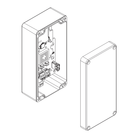
Page 7: Mount The Pim400-485
1. Remove the cover and place the PIM400-485 against the wall in the location where it successfully passed the pre-installation test. 2. Mark the four (4) mounting hole locations on the wall with a pencil using the PIM400-485 enclosure as a template. -
Page 8: Wire Routing
(version 2), complete the following steps: 1. Disconnect all electrical connections to the PIM400-485 (version 1) PCBA. 2. Remove the four screws from the PIM400-485 (version 1) PCBA. Set aside two (2) of the screws for later use. 3. Remove the PIM400-485 (version 1) PCBA from the enclosure. -
Page 9: Pim400-485 To Acp Connection
PIM400-485 to ACP connection Review Components on page 4 and page 5 before connecting the PIM400-485 to an Access Control Panel. CAUTION: Disconnect the Access Control Panel power and batteries before wiring the PIM400-485 to the panel. WARNING: Because every Access Control Panel is different, always check the panel’s instruction manual for appropriate interface wiring. -
Page 10: Typical Pim400-485 To Acp Wiring Diagrams
UL294 or ULCS318/ − ULCS319 Listed power limited 250mA 12 or 24 V DC RS485 PIM400-485 18 AWG, 1000 feet max. run length Access Control Panel RDA- TDA- RDB+ TDB+ Shield PIM400-485 Version 2 10 • Schlage • PIM400-485 user guide... - Page 11 Listed power limited 250mA Remove Jumpers 12 or 24 V DC − 18 AWG, 1000 feet max. run length TDB+ RDB+ TDA- RDA- Access Control Panel RDA- TDA- RDB+ TDB+ Shield PIM400-485 Version 1 11 • Schlage • PIM400-485 user guide...
-
Page 12: Optional Remote Antenna
(6 dB gain) Link mode The PIM400-485 can be placed into link mode using the Schlage utility software (SUS) on the handheld device (HHD). Refer to the Schlage utility software user guide for information. The PIM400-485 can also be placed into Link Mode directly through select Access Control Panels. -
Page 13: Dc Power
DC power This connection is always required regardless of the system application or configuration. Refer to page 9 for instructions to connect DC power to the PIM400-485. Complete the installation After all required connections have been made, connect the power and Access Control Panel standby batteries (optional) to the panel. - Page 14 Wireless Wireless Access Point Module. Access Point Module See Link mode on page 12 for (WAPM). more information. Also refer to the Wireless Access Point Module’s User Guide for Link instructions. 14 • Schlage • PIM400-485 user guide...
-
Page 15: Fcc / Ic Statements
Note: The intended use of this module is not for the general public. It is generally for industry/commercial use only. This transceiver is to be professionally installed in the end product by Allegion, and not by a third party. The Schlage XPB-COMAD400V2 900 MHz Communication Board Module will not be sold to third parties via retail, general public or mail order. - Page 16 Approved antenna list: The required antenna impedance is 50 ohms. PCB trace antenna with a 5.7dBi maximum gain p/n: 23520587, Dual Beam Antenna with a 3.5dBi gain (ANT400-REM-HALL) p/n: 23530579, Multi band Directional Panel antenna with 8.5dBi gain (ANT400-REM-I/O+dB) p/n: 23530553, Dual Band Quasi-Omni Panel Antenna with 4.5dBi gain (ANT400-REM-I/O) p/n: 23520561, Multi band Omni Antenna with 2dBi gain (ANT400-REM-CEILING) Antennas having a gain greater than the antenna type approved in the list are strictly prohibited for use with this device.
Need help?
Do you have a question about the PIM400-485 and is the answer not in the manual?
Questions and answers