
Related Manuals for Magnetrol C29


Summary of Contents for Magnetrol C29
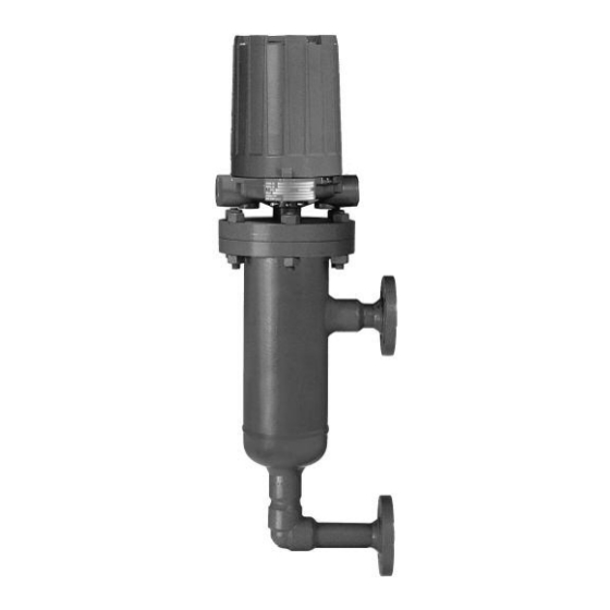
- Page 1 Flanged External Cage Installation and Operating Manual Float ctuated Liquid Level Switches...
- Page 2 Conventions Used in this Manual MAGNETROL reserves the right to make changes to the Certain conventions are used in this manual to convey products described in this manual at any time without specific types of information.
-
Page 3: Table Of Contents
6.1.1 Parts identification........18 2.1 Description............... 7 6.1.2 Switch and housing reference....... 18 2.2 Theory of Operation..........7 6.1.3 Model C29...........18 2.3 Operating Cycle............7 6.1.4 Models D30, J30 and L30......19 2.4 Switch Differential Adjustment......... 7 6.1.5 Models B60 and C60........19 2.4.1 Low level controls...........8... -
Page 4: Installation
Installation Caution: If equipment is used in a manner not specified by manu- facturer, protection provided by equipment may be impaired. Unpacking Unpack the instrument carefully. Inspect all units for damage. Report any concealed damage to carrier within 24 hours. Check the contents against the packing slip and purchase order. -
Page 5: Mounting
Caution: This instrument is intended for use in Installation Category II, Pollution Degree 2 locations. Adjust piping as required to bring control to a vertical position. Magnetrol controls must be mounted within 3° ® of vertical in all directions. A three-degree slant is noticeable by eye, but installation should be checked with a spirit level on top and/or sides of float chamber. - Page 6 NOTE: Housing must be grounded via protective ground screw in the base of the housing. NOTE: On high temperature applications (above +250° F [+121° C] in float chamber), high temperature wire should be used between control and first junction box located in a cooler area. On non-hazardous applications, flexible conduit may be used between the control and the first junction box.
-
Page 7: Reference Information
Reference Information Description Flanged External Cage liquid level switches are completely self-contained units designed for side mounting to a vessel or tank with threaded or flanged pipe connections. Theory of Operation The design of float-operated level switches is based upon the principle that a magnetic field will not be affected by non-magnetic materials such as 316 stainless steel The float moves a magnetic attraction sleeve within a... -
Page 8: Low Level Controls
The differential, or the amount of level travel between switch-on and switch-off, may be adjusted by reposition- For access to bottom Slight play (gap) jam nuts, remove top must be allowed ing the lower jam nuts on the float stem. This adjustment jam nuts, washer, and (.03"... -
Page 9: High Level Controls
7. Lift enclosing tube, switch, and base off float chamber. Jam nuts and attraction sleeve are now accessible. 8. Measure the distance “D” from the top edge of the upper jam nuts to the top of the float stem. Refer to Figure 7 Record this measurement. -
Page 10: Replacement Of Standard Float And Stem Assembly
NOTE: When reassembling the enclosing tube or the upper flange assembly to the control, tighten according to the following torque values. Model Flange Bolting Enclosing Tube C29, D30 55–60 ft–lbs 200–225 ft–lbs C60, J30, L30 100–125 ft–lbs 75–100 ft–lbs 250–300 ft–lbs 200–225 ft–lbs... -
Page 11: Troubleshooting
Troubleshooting Usually the first indication of improper operation is failure of the controlled equipment to function, i.e., pump will not start (or stop); signal lamps fail to light, etc. When these symptoms occur, whether at time of installation or during routine service thereafter, check the following potential external causes first. -
Page 12: Check Sensing Unit
Check Sensing Unit 1. Reconnect power supply. Carefully actuate the switch mechanism manually (use a non-conductive tool on electri- cal switch mechanisms) to determine whether controlled equipment will operate. Caution: With electrical power on, care should be taken to avoid contact with switch leads and connections at terminal block. -
Page 13: Preventive Maintenance
11. Check float to be certain it is buoyant in the liquid (float chamber or vessel must have adequate liquid level). If float is determined to be filled with liquid, or it is collapsed, it Top jam must be replaced immediately. nuts Bottom jam Caution: Do not attempt to repair a float. -
Page 14: Inspect Entire Unit Periodically
screw at point of contact between screw and lever.Such wear can cause false switch actuating levels. See switch mechanism bulletin supplied with control should switch adjustment or replacement become necessary. 2. DO NOT operate your control with defective or malad- justed switch mechanisms. -
Page 15: Specifications
Specifications Agency Approvals AGENCY APPROVED MODEL AREA CLASSIFICATION All with an electric switch mechanism and a housing Non-Hazardous TYPE 4X listed as TYPE 4X Class I, Div 1, Groups C & D All with an electric switch mechanism and a housing Class II, Div 1, Groups E, F &... -
Page 16: Physical
& Socket Weld Upper Side/Bottom Side/Side Levels C29 .76 10.00 3.56 14.44 13.81 6.87 18.25 14.46 6.87 18.94 2.07 2.97 254 463 367 174 481 52 D30 .65 8.75 3.81 13.25 13.06 7.12 17.56 13.71 7.12 18.25 1.50 2.33 222 446 348 180 463 38 J30 .48... - Page 17 Inches (mm) 5.93 (151) 3.78 (96) 8.46 10.12 (215) 8.46 (257) 10.12 (215) (257) plugged plugged Threaded and Socket Weld Side/Bottom Flanged 5.93 (151) 3.78 (96) Conduit Connections D Electrical Switches TYPE 4X/7/9: 1" NPT 8.46 Group B: 1" NPT 10.12 (215) Pneumatic Switches...
-
Page 18: Replacement Parts
Screws Float and stem assembly Jam nuts Guide washer Attraction sleeve Stop tube (not required for Models C29 and D30) IMPORTANT: When ordering, please specify: A. Model and serial number of control. B. Replacement assembly (kit) part number. 6.1.2 Switch and housing reference... -
Page 19: Models D30, J30 And L30
6.1.4 Models D30, J30 and L30 Housing cover Refer to Section 6.1.2 Housing base Refer to Section 6.1.2 Switch mechanism Refer to Section 6.1.2 ➀ ➁ Enclosing tube kit 089-5915-001 089-5933-011 includes items 4 and 5 Enclosing tube gasket 012-1204-001 012-1301-002 Head flange kit 089-4204-001... -
Page 20: Tandem Flanged External Cage Models
Tandem Flanged External Cage Models 6.2.1 Parts identification Housing cover Housing base Switch mechanism Enclosing tube Enclosing tube gasket Head flange Studs and bolts Hex nuts Flange gasket Stop strap Screws Upper float and stem assembly Lower attraction sleeve Spacer washer Retaining ring Jam nuts Upper attraction sleeve... -
Page 21: Model C29
6.2.3 Model C29 TDM Housing kit: includes items 1 and 2 Refer to Section 6.2.2 Switch mechanism Refer to Section 6.2.2 Enclosing tube kit: includes items 4 and 5 89-5909-002 Enclosing tube gasket 12-1204-001 Head flange kit: includes items 5, 6, 7, 8, and 9... -
Page 22: Model Numbers
Model Numbers MODEL NUMBER CODE Minimum Specific Gravity ➁ ➀ Pressure Rating for Models with Material of Construction Code Model psig @ ° F bar @ ° C 1000 0.76 0.81 D30 ➂ 0.65 0.69 — — 400 √ 322 √ 28 √... - Page 23 ELECTRIC SWITCH MECHANISM AND ENCLOSURE All models with All models with Process ➄ Material of Construction Code 1 Material of Construction Code 2 TYPE 4X/7/9 Aluminum Enclosure ➅ Temperature Switch Contacts Range Description Points °F (°C) Class I, Div 1 Class I, Div 1 Class I, Div 1 Class I, Div 1...
- Page 24 705 Enterprise Street • Aurora, Illinois 60504-8149 • 630-969-4000 • Fax 630-969-9489 info@magnetrol.com • www.magnetrol.com Copyright © 2017 Magnetrol International, Incorporated BULLETIN: 46-605.20 EFFECTIVE: February 2017 Magnetrol & Magnetrol logotype are registered trademarks of Magnetrol International, Incorporated. Hastelloy is a registered trademark of Haynes International, Inc. SUPERSEDES: January 2015...
Need help?
Do you have a question about the C29 and is the answer not in the manual?
Questions and answers